Creating various 3D Models like Furniture, Footing, Girder, Column drop with panel and Gable Wall in AutoCad
Creating various 3D Models like Furniture, Footing, Girder, Column drop with panel and Gable Wall in AutoCad
Introduction: 3D model is a type that shows the objects in 3D view. Tools used are extrude,region,shade,union,substract and etc.3D drawing are drawn by using autocad software.
1.Aim : To Create a 3D Furniture element as shown in the Figure. Assume dimensions which are missing.
Commands used:
- Units
- Limits
- Layers
- 3d orbit
- 3d face
- Dimlinear
- Rectangle
- Box
- Extrude
- Region
- Boundary
Procedure :
Step 1:
- Create a new AutoCAD file with imperial settings.
- Command D - units type as "Engg" and set the precision also
- Set the limits with command "LIMITS" and enter zoom all.
- Command - UNITS to change the unit option as "Engg" and set the precision.
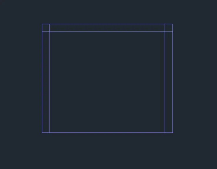
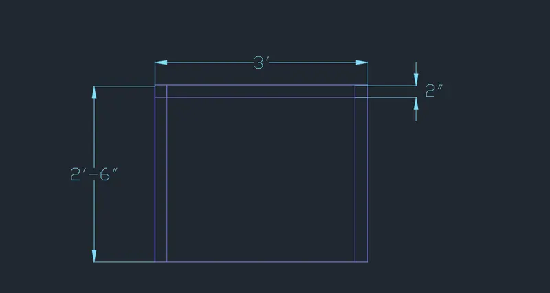
- Command - Box, create it of length 3' and width as 2'6" and height 2'6" in top view
- Draw a line 2" from the right side and the front view.
Step 2:
- Command - Dimlinear
- Select the object and specify the distance on all the three sides
- Select the layer properties from the toolbar and select the layers for the wall and dimension.
Step 3 :
- Select view option from the view manager
- From the top left corner select the option as 2d wireframe
- Command - Extrude
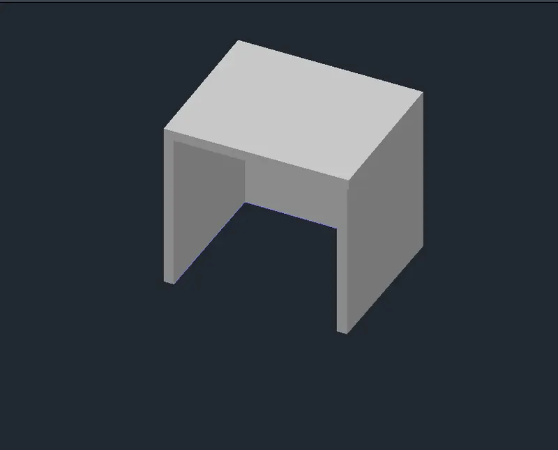
- Extrude the rectangle in Z axis to an height of 2'4"
- From the top left corner select the option as Shaded.
- Command - 3dorbit, to rotate the object as required
Result : The 3D model of the furniture element has been created.
***************
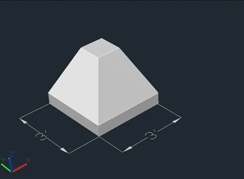
2.Aim : To Create the 3d Model of an Isolated footing as shown in Figure.
Commands used:
- Units
- Limits
- Layers
- 3d orbit
- 3d face
- Dimlinear
- Rectangle
- Extrude
- Region
- Boundary
Procedure :
Step 1:
- Create a new AutoCAD file with imperial settings.
- Command D - units type as "Engg" and set the precision also
- Set the limits with command "LIMITS" and enter zoom all.
- Command - UNITS to change the unit option as "Engg" and set the precision.
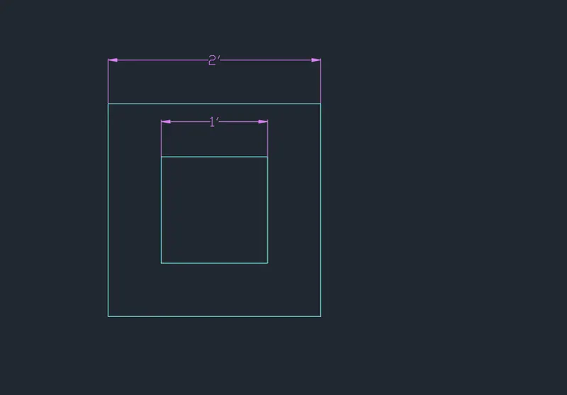
- Command - line, Draw a square of length and width as 2'
- Command - line, Draw a iner square of length and width as 1'
- Select layer from layer properties and form a layer for the objects and the dimensions.
- Command - Dimlinear, mark the dimensions as per the layout.
Step 2 :
- Command - Region
- Select the object and form as a single region
- Command - Extrude
- Selct the object and specify the extruded height of about 6"
- Select the top view from the cube option
- Draw offset of square at 2' to form topmost portion of footing.
- And then move it in z direction at 2'.
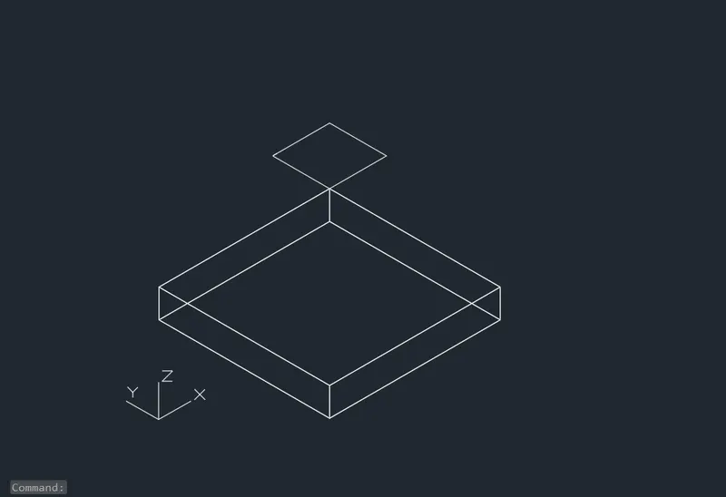
Step3:
- Join all the four points and form a isolated footing
- Command - 3dface, select the object and shade it using the command
- Command - Dimlinear, mark the dimensions as per the layout.
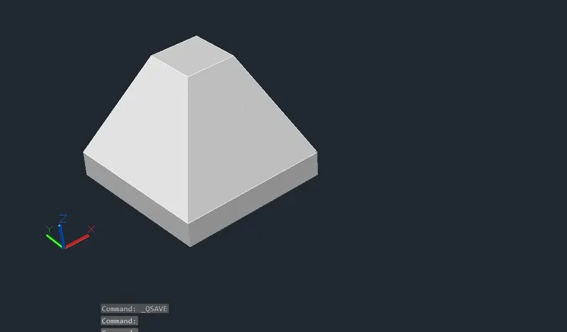
Result : The 3d Model of an Isolated footing is created.
*************
3. Aim : To Create the 3D view of the AASTHO Type Girder.
Commands used:
- Units
- Limits
- Layers
- 3d orbit
- 3d face
- Dimlinear
- line
- Extrude
- Region
- Boundary
Procedure :
Step 1:
- Create a new AutoCAD file with imperial settings.
- Command D - units type as "Engg" and set the precision also
- Set the limits with command "LIMITS" and enter zoom all.
- Command - UNITS to change the unit option as "Engg" and set the precision.
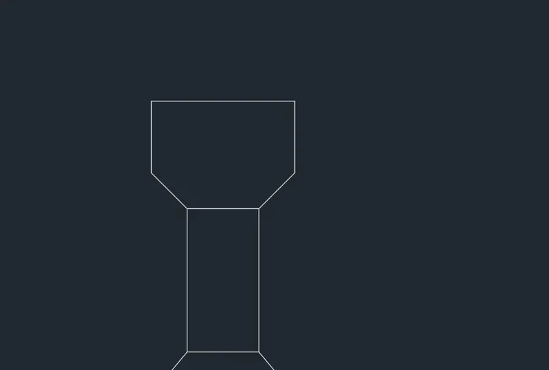
- Command - Line and draw a line of 1'6" at the bottom
- Give a taper distance and join web and flange Mirror the same on the other side
- Command - offset 6" from last line and taper the sides.
- Command - Line and draw a line of 1'6" towards top
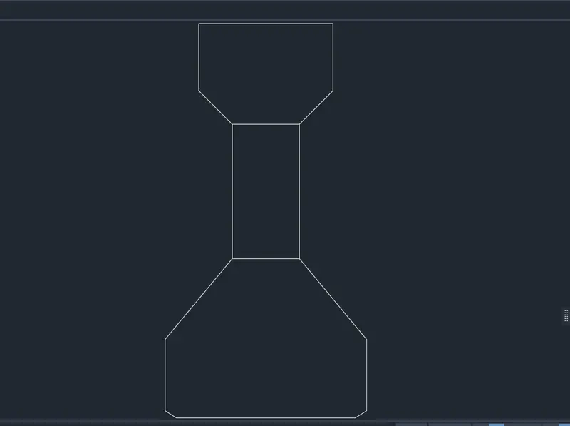
Step 2 :
- Command - Dimlinear
- Select the object and mark the dimension as per the given layout.
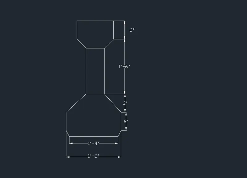
Step 3 :
- Select the isometric view from the view option
- Command - Region
- Select the object and form as a single region
- Command - Extrude
- Selct the object and specify the extruded height of about 10'
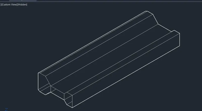
Step 4 :
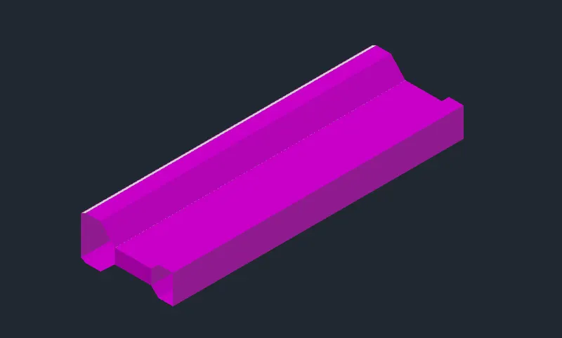
- From the top left corner select the option as Shaded.
- Command - 3dorbit, to rotate the object as required
Result : The 3D view of the AASTHO Type Girder
****************
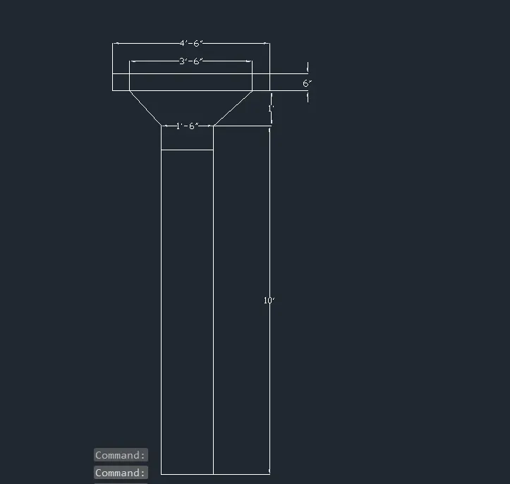
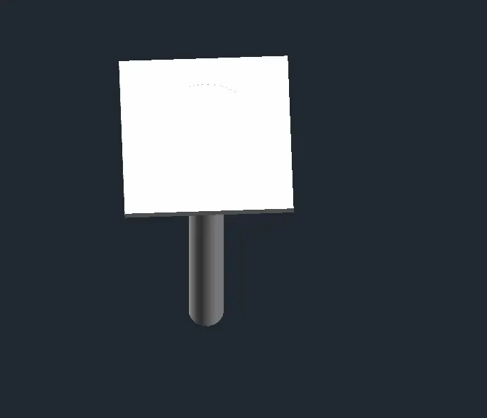
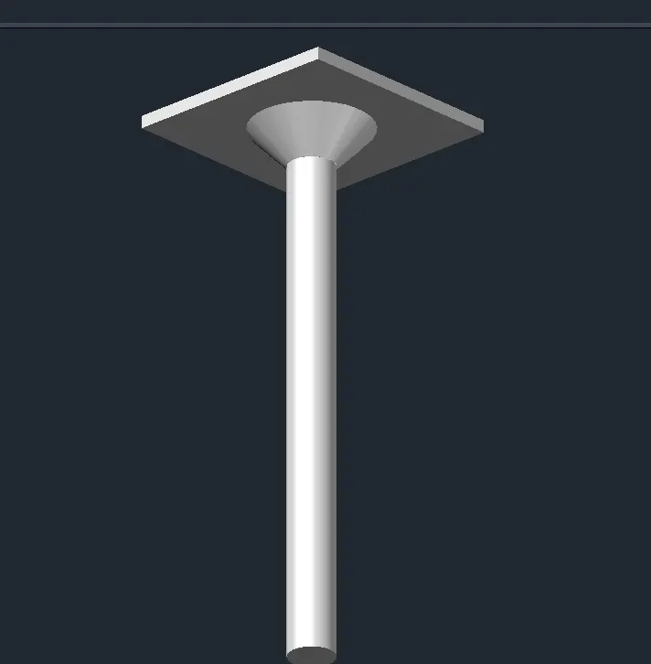
4. Aim : To Create a 3d Model of a drop column with panel as shown in section and isometric view.
Commands used:
- Units
- Limits
- Layers
- 3d orbit
- 3d face
- Dimlinear
- line
- Circle
- Extrude
- Region
Procedure :
Step 1:
- Create a new AutoCAD file with imperial settings.
- Command D - units type as "Engg" and set the precision also
- Set the limits with command "LIMITS" and enter zoom all.
- Command - UNITS to change the unit option as "Engg" and set the precision.
- Command - Line, draw a column section of size as given in the layout
- COmmand - Dimlinear option to mark the dimension as per the layout.
Step 2 :
- In settings set the 3D Modelling and visual style control to 2D wire frame
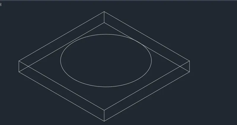
- Command - line, draw a square of size 4'-6"
- Command - Region and press enter, and select the square created to convert it.
- Command Extrude
- Select the square and extrude the object to an height of 6"
- Command - Circle, draw a draw a circle of diameter at the center portion of the extruded square
Step 3 :
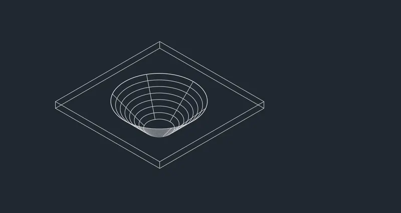
- Command - Region and press enter, and select the Circle created to convert it.
- Command - Extrude option, select the circle and click on Tamper, select the angle as 45 and and height as 2".
- Now explode the tampered circle and convert the top circle into a region.
Step 4 :
- Click on Extrude option in home tab and then select the circle and extrude at a height of 10' to form the drop column.
- From the top left corner select the option as Shaded.
- Command - 3dorbit, to rotate the object as required.
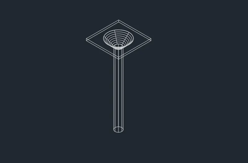
Result : The 3d Model of a drop column with panel as shown in section and isometric view has been created.
*****************
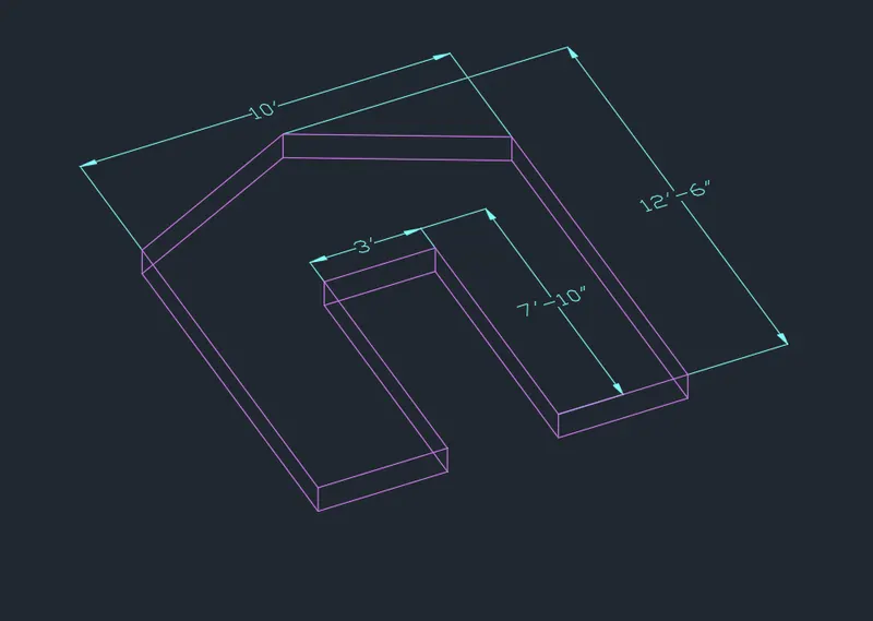
5. Aim : To Create the 3d model of a wall as shown in Figure
Commands used:
- Units
- Limits
- Layers
- 3d orbit
- 3d face
- Dimlinear
- Offset
- line
- Circle
- Extrude
- Region
- Trim
Procedure :
Step 1:
- Create a new AutoCAD file with imperial settings.
- Command D - units type as "Engg" and set the precision also
- Set the limits with command "LIMITS" and enter zoom all.
- Command - UNITS to change the unit option as "Engg" and set the precision.
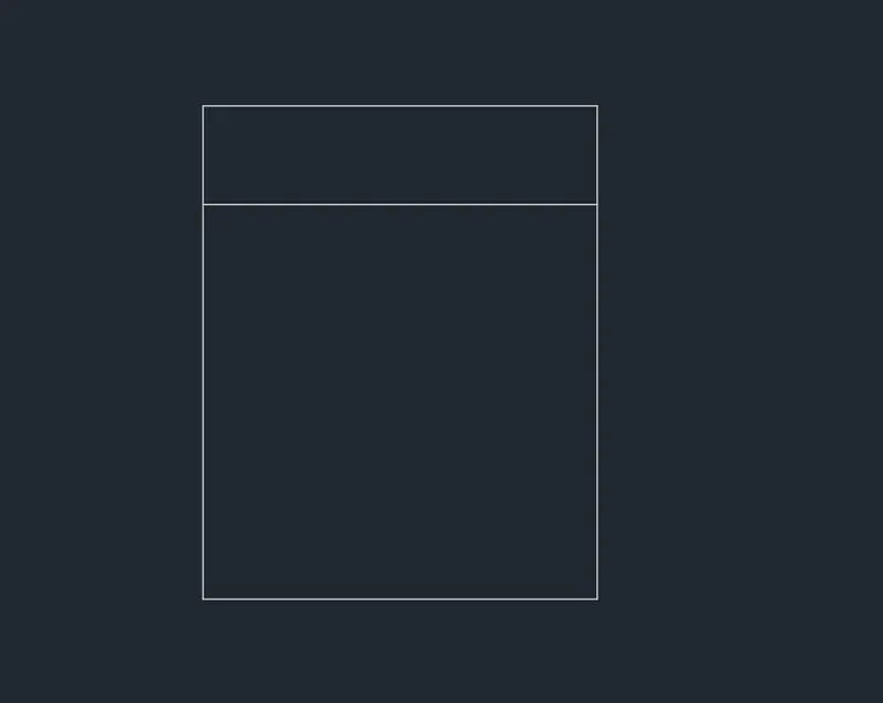
- Command - Line, specify the 1st point and draw a line of length 10' horizontally and 12'6" vertically
- Command - offset
- Select the object and through option and specify the offset distance.
Step 2:
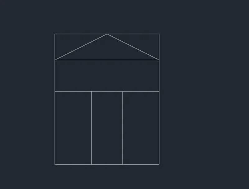
- Command - offset
- Select the object and through option and specify the offset distance of 7' from the bottom portion
Step 3:
- Command - Trim
- Select the object and remove the unwanted line
- Command - Dimlinear option to mark the dimension as per the layout.

Step 4:
- Select layer from layer properties and form a layer for the objects and the dimensions.
- Select the isometric view from the view option
- Command - Region
- Select the object and form as a single region
- Command - Extrude
- Selct the object and specify the extruded height of about 9"
- Command - 3dorbit, to rotate the object as required.
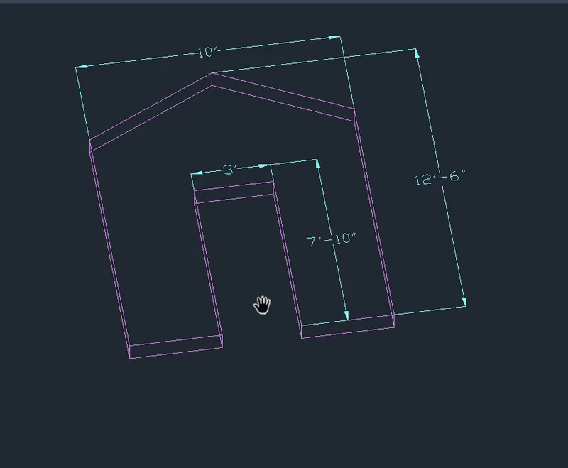
Result : The 3d model of a wall as shown in Figure has been created.
*****************