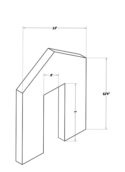
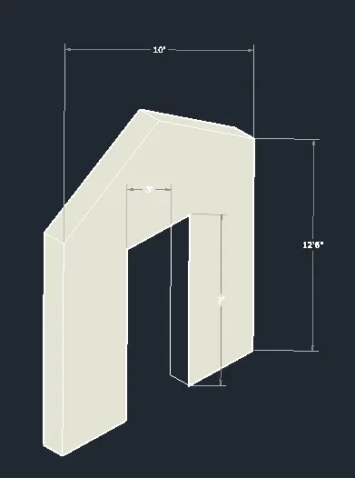
Creating various 3D Models like Furniture, Footing, Girder, Column drop with panel and Gable Wall in AutoCad
CHALLENGE 12:
Creating various 3D Models like Furniture, Footing, Girder, Column drop with panels, and Gable Walls in AutoCad
AIM:
To Create various 3D Models like Furniture, Footing, Girder, Column drop with panels, and Gable Walls in AutoCad
INTRODUCTION:
This 3D modelling has 3 types of modelling techniques they are, wireframe modelling, solid modelling and surface modelling. Creating various 3D Models like Furniture, Footing, Girder, Column drop with panels, and Gable Walls in AutoCad.The commonly used commands to create this 3D model are the 3D face,3Dorbit, and Solid modelling techniques like Box, poly solid, Extrude, revolve, sweep, union, and subtract commands.
QUESTION NO:1
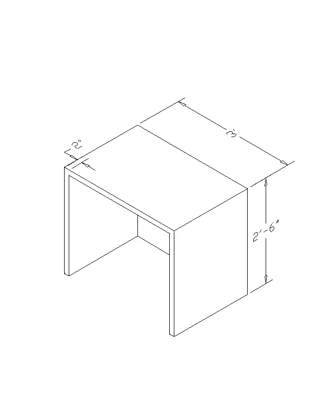
Create a 3D Furniture element as shown in the Figure. Assume dimensions which are missing.
PROCEDURE:
- Open AutoCAD software and open a new drawing.
- Set the necessary limits and units.
- To change the workspace in 3d basics and 3d modelling.
- Set view cube and UCS in the workspace.
- Type the REC command window and press enter

- Specify the first point: Type (0,0) at the command prompt and press enter(starting point)
- Specify the Next point: Type (@3',2'6") at the command prompt and press enter
- Now press the home button in the view cube to change the 3-dimensional view.
- Click the corner point from the rectangular section, to draw the line in the Z axis -2'6".
- Now offset the 2" wall other portion of the rectangular section.
- Similarly, drawing the line to join the 2" wall parallel to the rectangular portion.
- After that provide dimension top portion 3'.
- Now click the UCS command and face its front side to provide the dimensions of 2'6" and 2" walls, respectively.
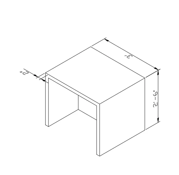
- Now to ready for 3D furniture element as per required size.
RESULT:
QUESTION NO:2
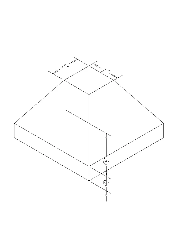
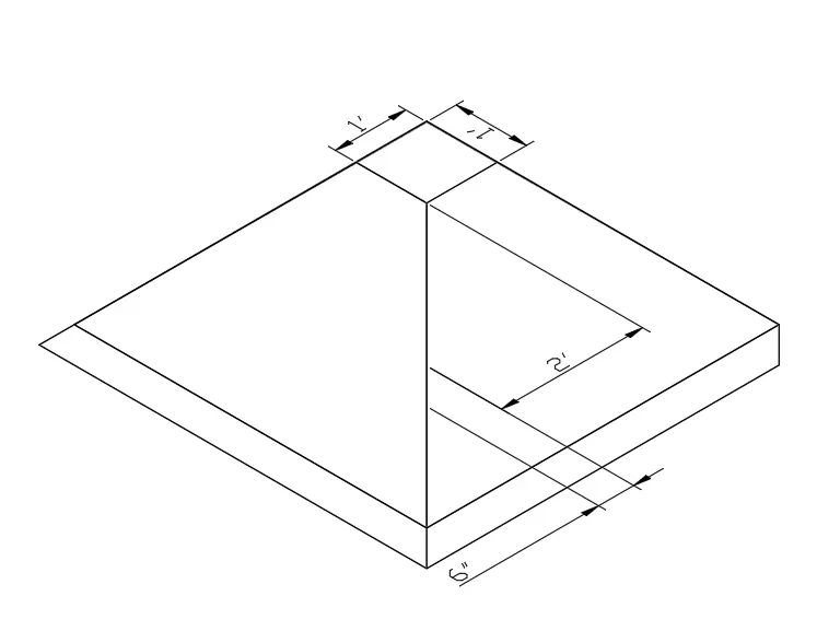
Create the 3d Model of an Isolated footing as shown in Figure.
PROCEDURE:
- Open AutoCAD software and open a new drawing.
- Set the necessary limits and units.
- To change the workspace in 3d basics and 3d modelling.
- Set view cube and UCS in the workspace.
- Type the REC command window and press enter
- Specify the first point: Type (0,0) at the command prompt and press enter(starting point)
- Specify the Next point: Type (@1',1') at the command prompt and press enter
- Now press the home button in the view cube to change the 3-dimensional view.
- Type the REG command in the command prompt, and the rectangle is converted to the region.
- Explode the rectangle, now go to the offset command the distance is 6".
- Now go to the Extrude command then extrude them at a height of 2' below the z-axis.
- Now the drawing shows isolated footing, After that dimension all elements.
RESULT:
QUESTION NO:3
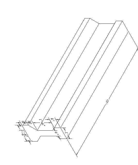
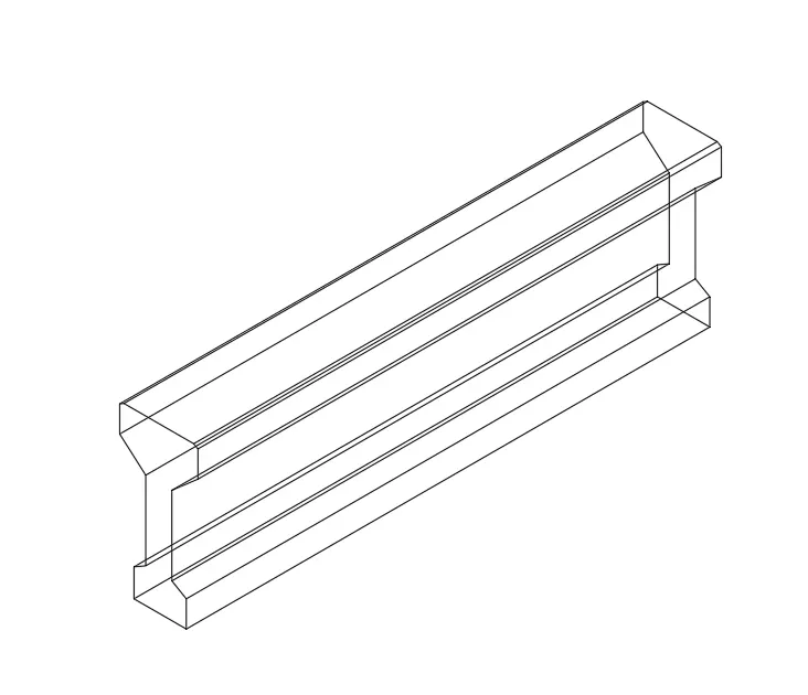
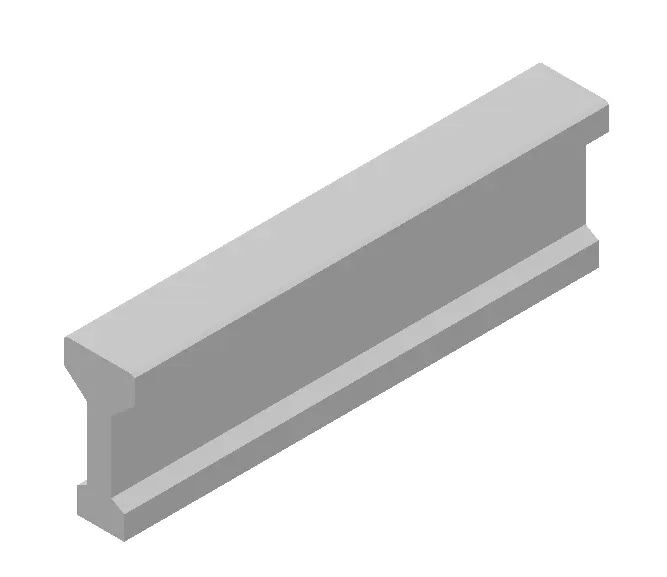
Create the 3D view of the AASTHO Type Girder.
PROCEDURE:
- Open AutoCAD software and open a new drawing.
- Set the necessary limits and units.
- To change the workspace in 3d basics and 3d modelling.
- Set view cube and UCS in the workspace.
- Type the REC command window and press enter
- Specify the first point: Type (0,0) at the command prompt and press enter(starting point)
- To draw the footing details in 2 dimensional.
- Take line command @ a distance is 1'6" and 1'4", similarly we have to draw the 6" vertical line and 1'6" vertical wall,1 ' horizontal wall to draw down the same lines on both sides up to get proper footing shape.
- Now draw the line 10' for path reference and then sweep to the object up to 10' height.
RESULT:
QUESTION NO:4
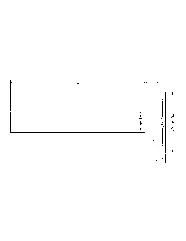
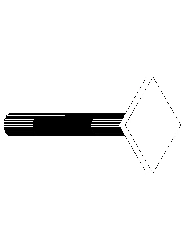
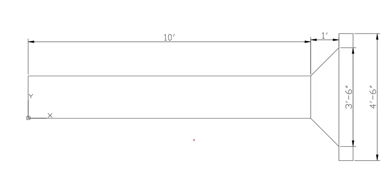
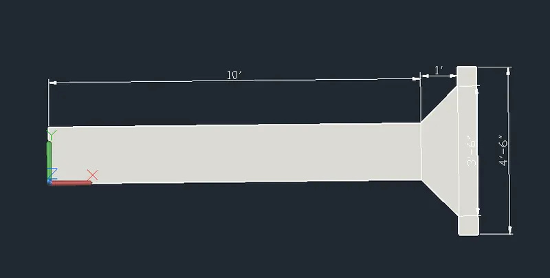
Create a 3d Model of a drop column with the panel as shown in the section and isometric view.
PROCEDURE:
- pen AutoCAD software and open a new drawing.
- Set the necessary limits and units.
- To change the workspace in 3d basics and 3d modelling.
- Set view cube and UCS in the workspace.
- Type the REC command window and press enter
- Specify the first point: Type (0,0) at the command prompt and press enter(starting point)
- To draw a rectangle @10',1'6".
- Now offsetting the distance 1' of horizontal line 3'6", then join the incline of the line and rectangle.
- Now draw a rectangle through a 3'6" horizontal line at a @6", and 4'6" respectively.
- After that mentioned its dimensions.
- Now go to 3D modelling, select the region command, and region it entire drawing.
- After that shaded the diagram we get the required drawing.
RESULTS:
QUESTION NO:5
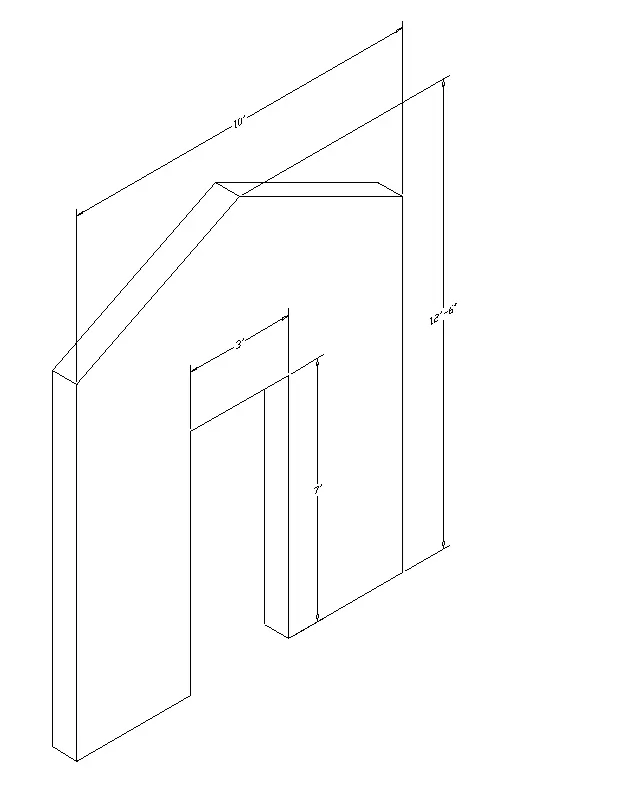
Create the 3d model of a wall as shown in Figure. Consider wall thickness as 9”.
PROCEDURE:
- pen AutoCAD software and open a new drawing.
- Set the necessary limits and units.
- To change the workspace in 3d basics and 3d modelling.
- Set view cube and UCS in the workspace.
- Type the REC command window and press enter
- Specify the first point @10',12'6".
- After that create a door with a size 3'X 7'.
- Now workspace changed to 3D modelling.
- By using a extrude command the wall is projected upward.
- by using Subtract command, subtract from the door portion in the entire wall.
- After that select the boundaries to make one region by using the boundary command.
- After go to the shaded option to represent the 3D view in the wall.
RESULTS: