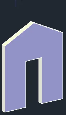
Creating various 3D Models like Furniture, Footing, Girder, Column drop with panel and Gable Wall in AutoCad
1) Ans
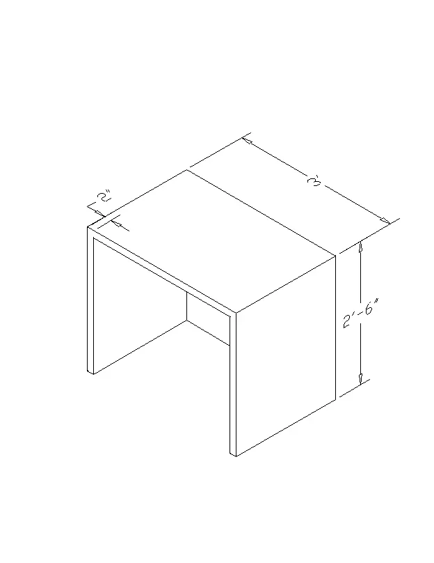
AIM:
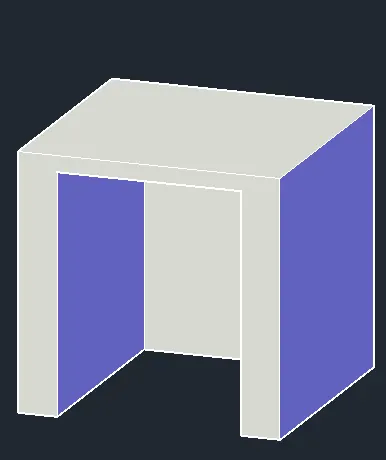
- Create a 3D Furniture element as shown in the Figure. Assume dimensions which are missing.
INTRODUCTION:
- Draw the drawing in the 3D modeling and use the various 3D command and use the UCSto Make easy and fast to the drawing in realstic.
PROCEDURE:
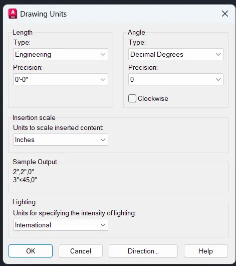
- Open to Autocad file and change units in Decimanls to Engineering
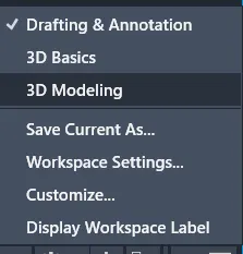
- Change to Drafting and Annotation to 3D Modeling
- Enter the command rec (Rectangle)
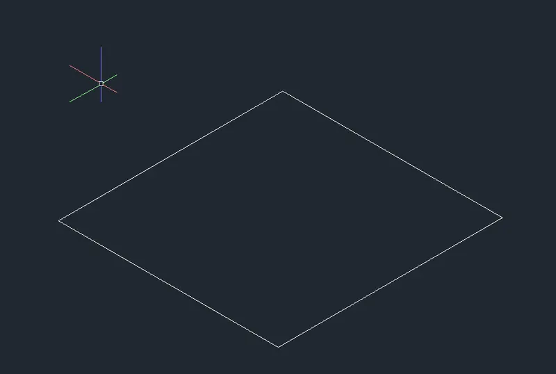
- Use the command Extrude and extrude to the Z Diection in 2'6"
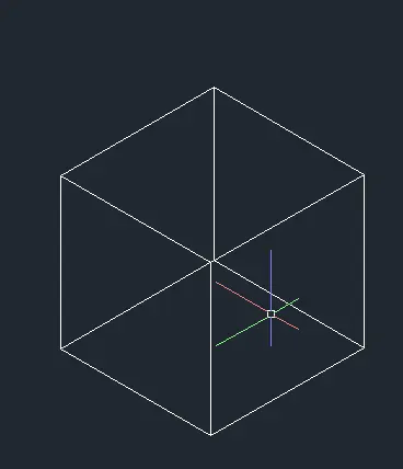
- Use the command UCS and Selected the face of the extruced object
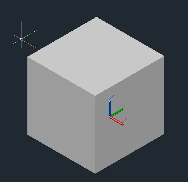
- Use the extrued object and use the subtrack command use suprate the inside of the extruded object
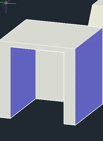
RESULT:
2) Ans
Create the 3d Model of an Isolated footing as shown in Figure.

INTRODUCTION:
- Draw the drawing in the 3D modeling and use the various 3D command and use the UCSto Make easy and fast to the drawing in realstic.
PROCEDURE :
- Draw the rectangle
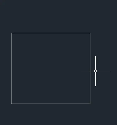
- Enter the rectangle inside of the box
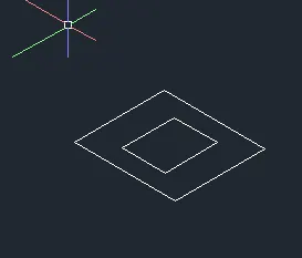
- Inside of the rectangle move in Z diection in 2'
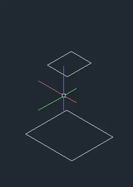
- Enter the Lof command selected two objects
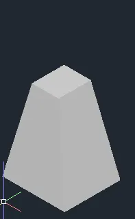
- Enter the presspull coimmand and use the bottom face
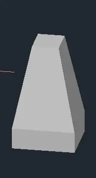
RESULT:
3) ANS
AIM: Create the 3D view of the AASTHO Type Girder.
INTRODUCTION:
- Draw the drawing in the 3D modeling and use the various 3D command and use the UCSto Make easy and fast to the drawing in realstic.
PROCEDURE :
- Draw to I section type of girder in dimensions
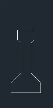
- Enter the command Region command Selected the objected.
- Enter the command Extrude upto 10'
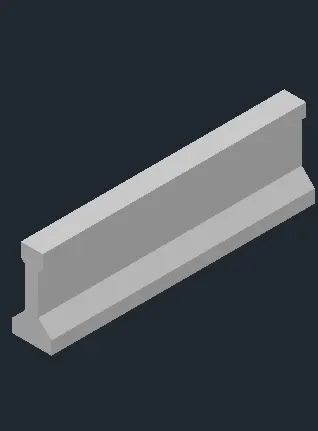
RESULT:
4) ANS
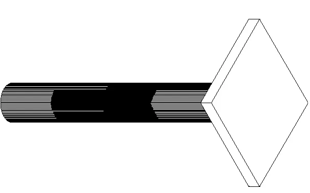
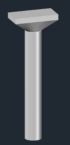
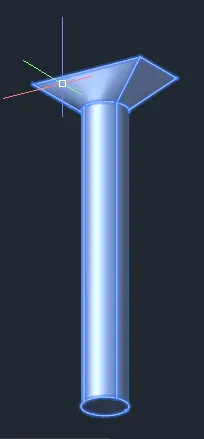
AIM:Create a 3d Model of a drop column with panel as shown in section and isometric view.
INTRODUCTION:
- Draw the drawing in the 3D modeling and use the various 3D command and use the UCSto Make easy and fast to the drawing in realstic.
PROCEDURE :
- Draw to the required rectangle use using rec command
- Draw in circle at rectangle box
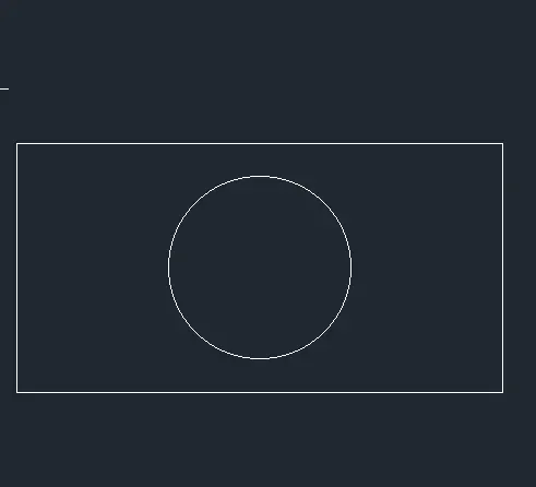
- Enter the move command in the Z diection in 1'
- Enter the lof command selceted the two objects
- Enter the presspull command option toward to -z Direction in 10'
RESULT:
5)ANS
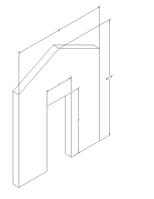
AIM: Create the 3d model of a wall as shown in Figure. Consider wall thickness as 9”.
INTRODUCTION:
- Draw the drawing in the 3D modeling and use the various 3D command and use the UCSto Make easy and fast to the drawing in realstic.
PROCEDURE :
- Draw to the required rectangle use using 2d Plane
- make to into the door required shape
- make it to a region to create the face
- the door required the shape
- it to a region to create the face
- use the extrude command and extured towards the Z - direction 9"
- make the face to the side and face direction