Creating various 3D Models like Furniture, Footing, Girder, Column drop with panel and Gable Wall in AutoCad
Create a 3D Furniture element as shown in the Figure. Assume dimensions which are missing.
AIM:
To create a 3D furniture element by using the tools in AutoCAD.
PROCEDURE:
- To create a sketch in 3D, we have to switch the workspace from drafting & annotation option to 3D modelling.
- There are four co-ordinate systems useful to draw the sketches in 3D,
- Relative Rectangular Co-ordinate System
- Relative Polar Co-ordinate System
- Relative Spherical Co-ordinate System
- Relative Cylindrical Co-ordinate System
- Select the command LINE and take the point from the origin and draw the line in x direction by using the suitable co-ordinate systems.
- By using the command LINE and complete the outer layer of the sketch as per the given dimensions.
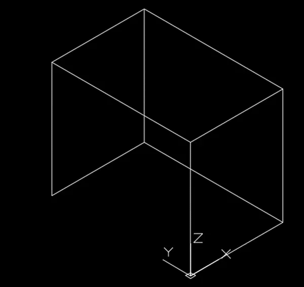
- After completing the outer layer of the sketch, then draw the inner side f the sketch by using the command LINE as per the given dimensions.
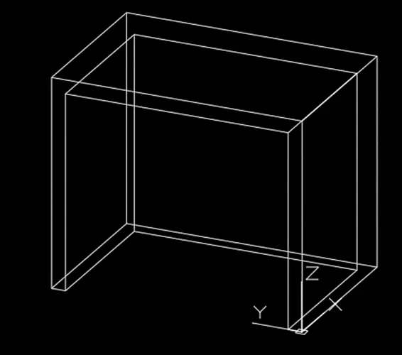
- After completing the drawing sketch, we have to create the sketch as furniture.
- Use the command 3DFACE or use the command REGION to create a surface on the top of the sketch.
- After giving surface to the sketch now we have to change view from 2D wireframe to the shaded view.
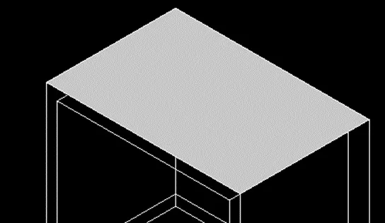
- Use the same command 3DFACE and complete the creation of surfaces to all sides and faces of the sketch.
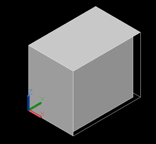
- After completing the sketch of furniture, change the view from shaded view to hidden view.
RESULT:
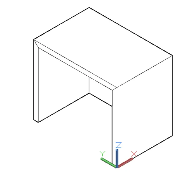
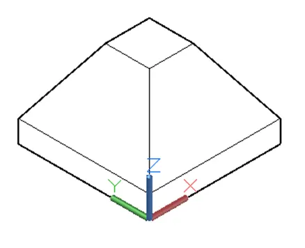
Create the 3d Model of an Isolated footing as shown in Figure.
AIM:
To create a 3D model of isolated footing by using the tools in AutoCAD.
PROCEDURE:
- To create a sketch in 3D, we have to switch the workspace from drafting & annotation option to 3D modelling.
- Select the command RECTANG and draw the rectangle as per given dimensions.
- Use the command OFFSET and draw the inner rectangle.
- Select the command COPY and select the outer rectangle and place it again in negative z-direction.
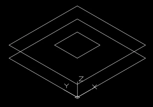
- Select the command MOVE then move the inner rectangle in positive z- direction as per the given dimensions.
- Use the command LINE to draw the connecting lines.
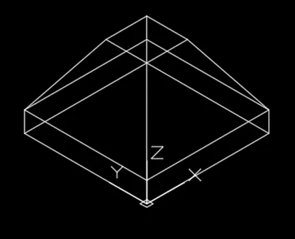
- After completing the drawing sketch, we have to create the sketch as isolated footing.
- Use the command 3DFACE or use the command REGION to create a surface on the top and sides of the rectangle.
- After giving surface to the sketch now we have to change view from 2D wireframe to the shaded view.
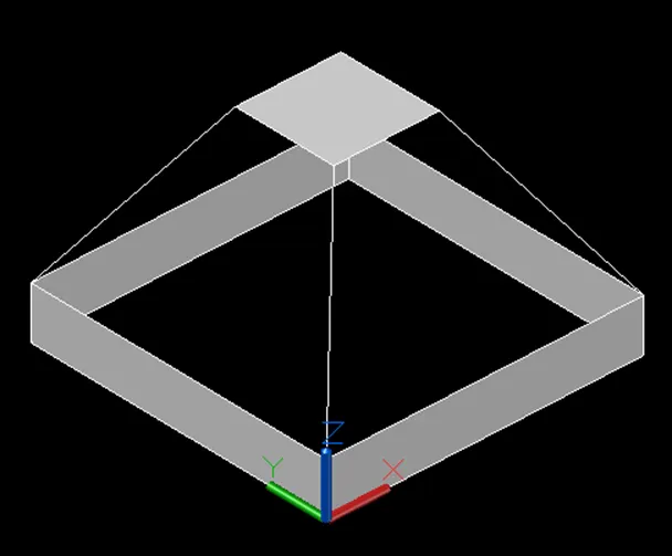
- Use the same command 3DFACE and complete the creation of surfaces to all sides and faces of the sketch.
- After completing the sketch of isolated footing, change the view from shaded view to hidden view.
RESULT:
Create the 3D view of the AASTHO Type Girder.
AIM:
To create the 3D view of the AASTHO type girder by using the tools in AutoCAD.
PROCEDURE:
- To create a sketch in 3D, we have to switch the workspace from drafting & annotation option to 3D modelling.
- Select the command LINE and draw the I section as per the dimensions.
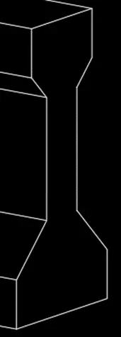
- Use the command LINE and draw the length of I section.
- Select the command COPY to place the extended line in specified places.
- Change the view of the I section to the back side and complete the joining the lines.
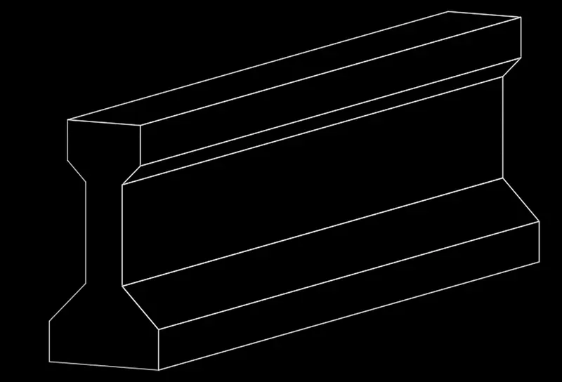
- Select the command REGION to give the surface to the I section.
- After giving surface to the sketch now we have to change view from 2D wireframe to the shaded view.
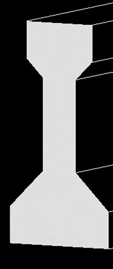
- Use the same command 3DFACE and complete the creation of surfaces to all sides and faces of the sketch.
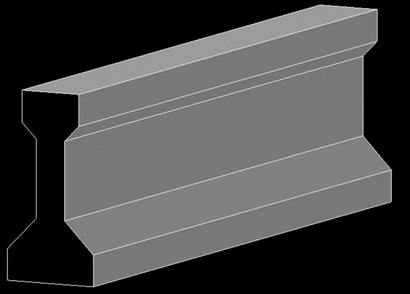
- After completing the sketch of AASTHO type girder, change the view from shaded view to hidden view.
RESULT:
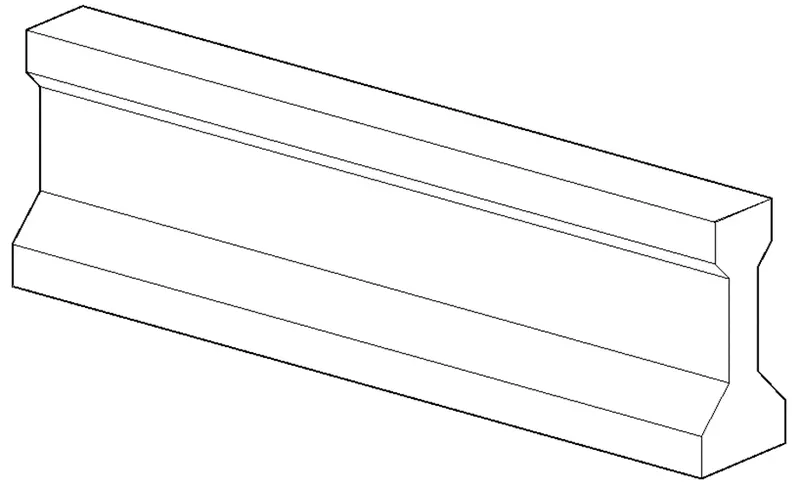
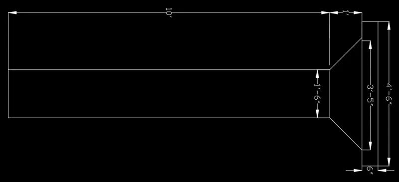
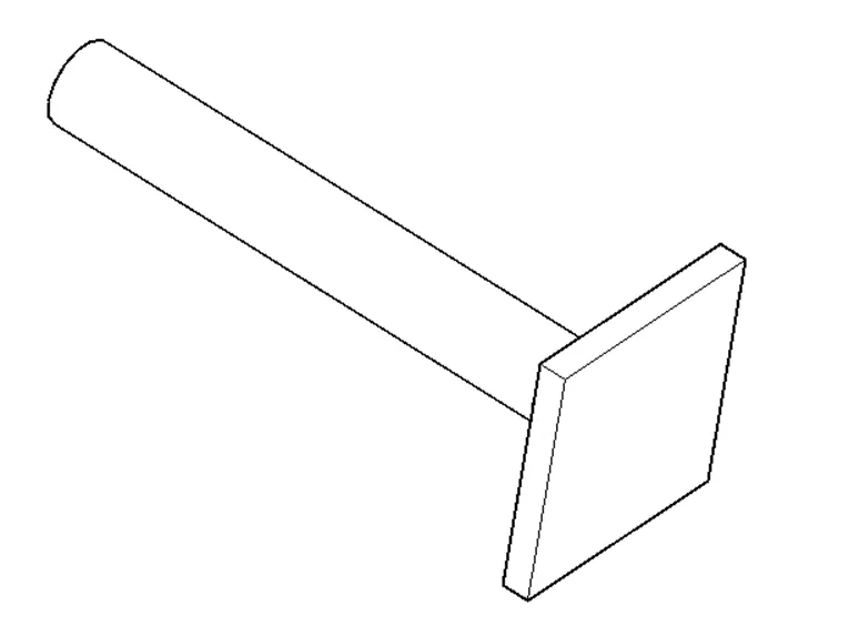
Create a 3d Model of a drop column with panel as shown in section and isometric view.
AIM:
To create a 3D model of a drop column with panel in section and isometric view by using the tools in AutoCAD.
PROCEDURE:
- To create a sketch in 3D, we have to switch the workspace from drafting & annotation option to 3D modelling.
- Select the command LINE and draw the section view of a drop panel as per the dimensions.
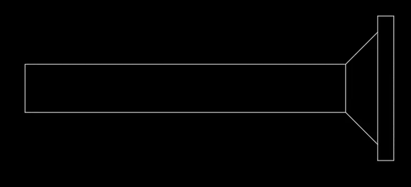
- After completing the section of the drop panel now we have to give the dimensions for the sketch.
- Use the command DIMLIN to give the required dimensions for the sketch.
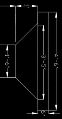
- After completing the sketch of sectional view of the drop panel now we have to draw the isometric view of the drop panel.
- Firstly, we have to draw the rectangle by using the command RECTANG as per the given dimensions.
- Select the command OFFSET to draw inner rectangle.
- Use the command CIRCLE to draw the circle as per the given dimensions.
- Use the command REGION to create a surface of the outer rectangle and also use the command EXTRUDE to create a outer rectangle as footing.
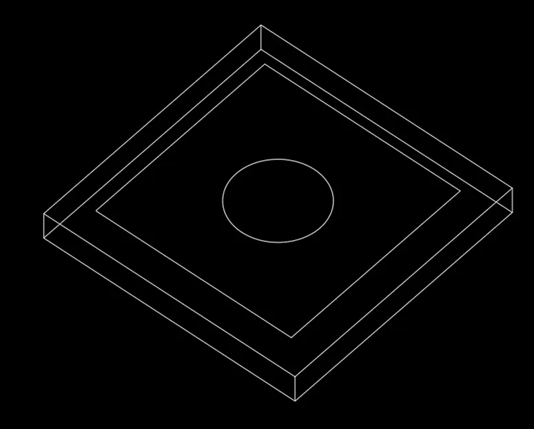
- After completing the first step, now we have to draw the panel.
- Use the command MOVE to move the circle in positive z direction as per the dimensions.
- Use the command LOFT to create a surface for the inner rectangle and the circle.
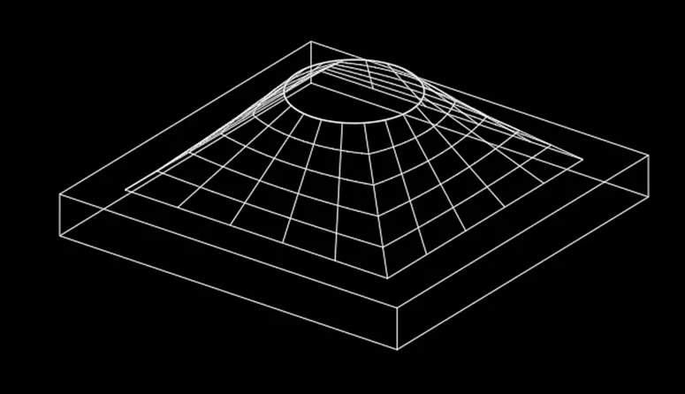
- Again, select the command CIRCLE to draw the circle above the circle.
- Use the command EXTRUDE to extend the circle to the certain height as per the dimension.
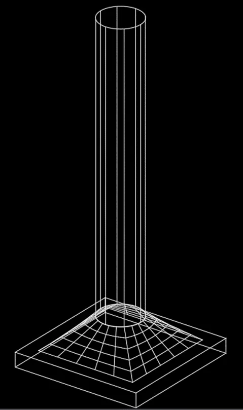
- After completing the sketch of drop panel, change the view from 2D wireframe view to hidden view.
RESULT:
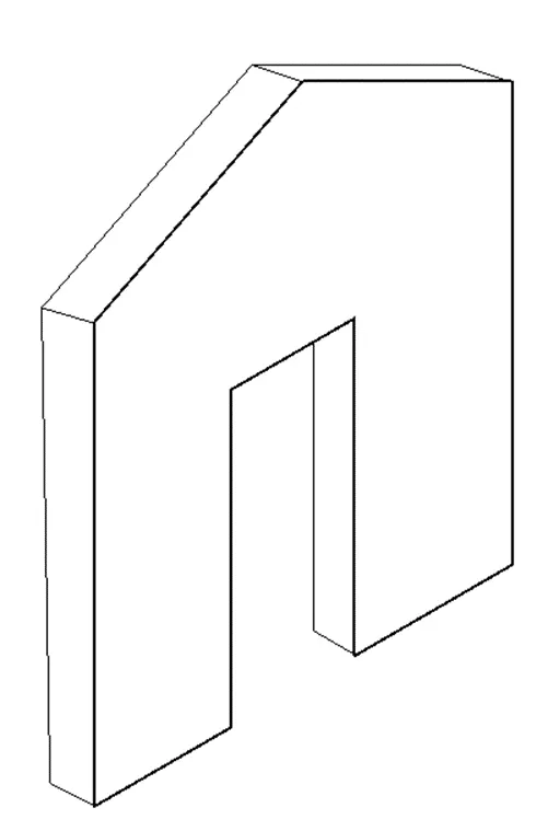
Create the 3d model of a wall as shown in Figure. Consider wall thickness as 9”.
AIM:
To create a 3D model of a wall by using the tools in AutoCAD.
PROCEDURE:
- To create a sketch in 3D, we have to switch the workspace from drafting & annotation option to 3D modelling.
- Select the command LINE and draw the outer side of the wall as per the dimensions.
- By using the same command LINE and draw the sketch of door opening on the wall.
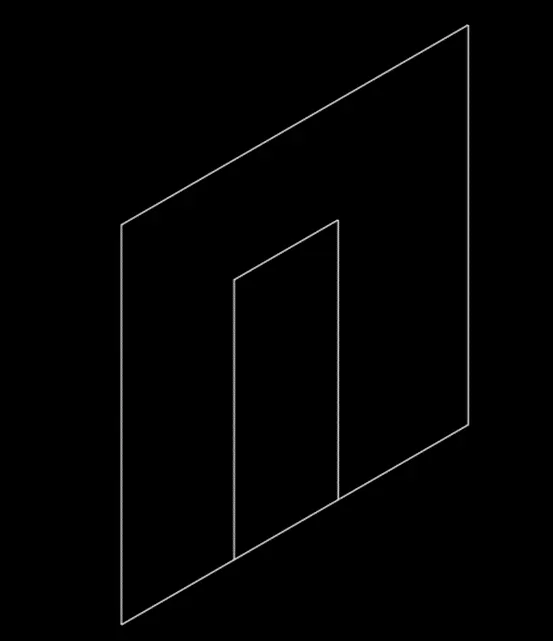
- After completing the sketch of outer surface of the wall we have to draw the thickness of the wall.
- Select the command LINE to draw the thickness of the wall as per the given dimension.
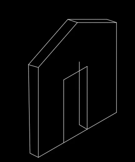
- Select the command REGION to give the surface to the outer side of the wall.
- After giving surface to the sketch now we have to change view from 2D wireframe to the shaded view.
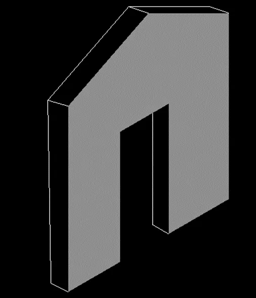
- Use the same command 3DFACE and complete the creation of surfaces to all sides and faces of the sketch.
- After completing the sketch of 3d model of the wall, change the view from shaded view to hidden view.
RESULT: