Creating various 3D Models like Furniture, Footing, Girder, Column drop with panel and Gable Wall in AutoCad
AIM
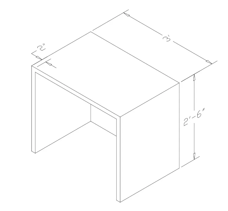
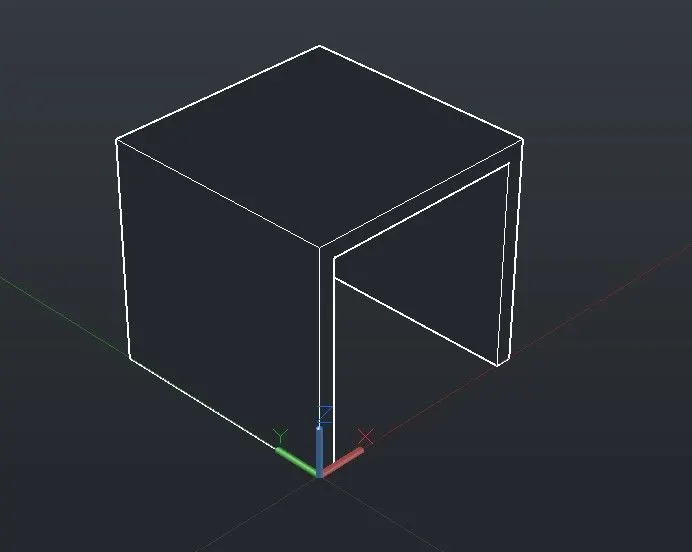
To create a 3D Furniture element as shown in the Figure
INTRODUCTION
Here we are using 3D modeling in AutoCAD
PROCEDURE
Step 1: Draw the line using coordinate system
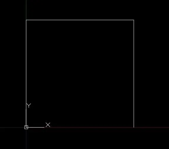
Step 2 :Take offset of 2”
Close the polygon
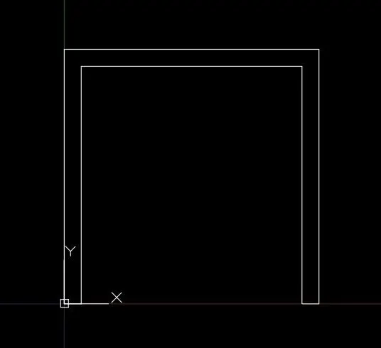
Step 3:Enter ‘REGION’ command and select the area
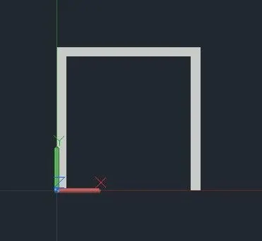
Step 4:Enter ‘ext’ command and extrude the area to 2’6”
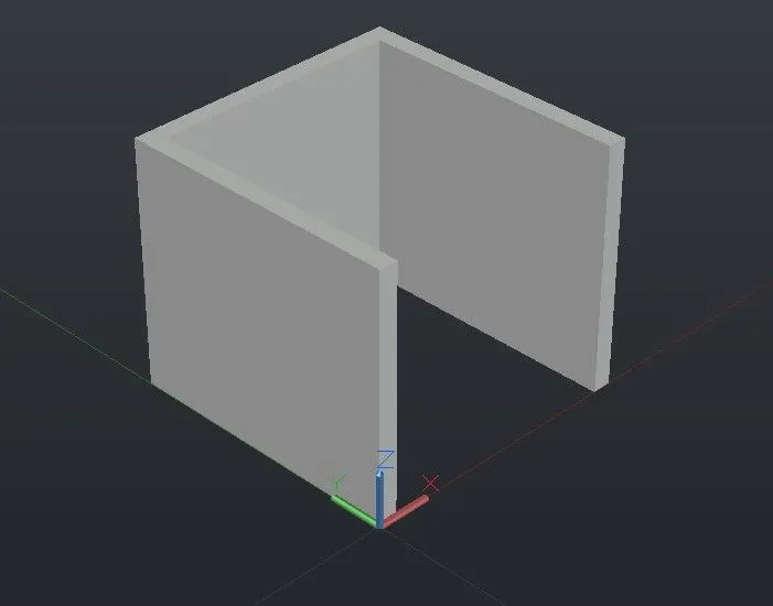
Step 5:Draw a rectangle on the top
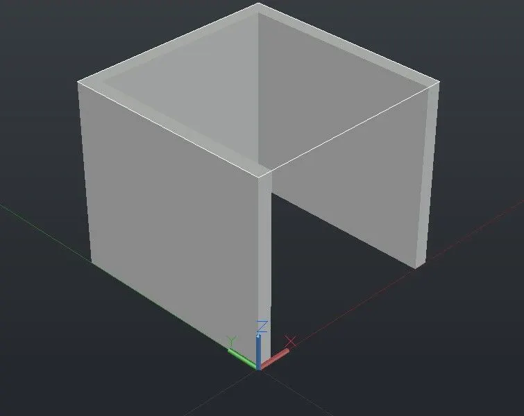
Step 6:Enter ‘REGION’ command and select the area
Step 7:Enter ‘ext’ command and extrude the area to 2”
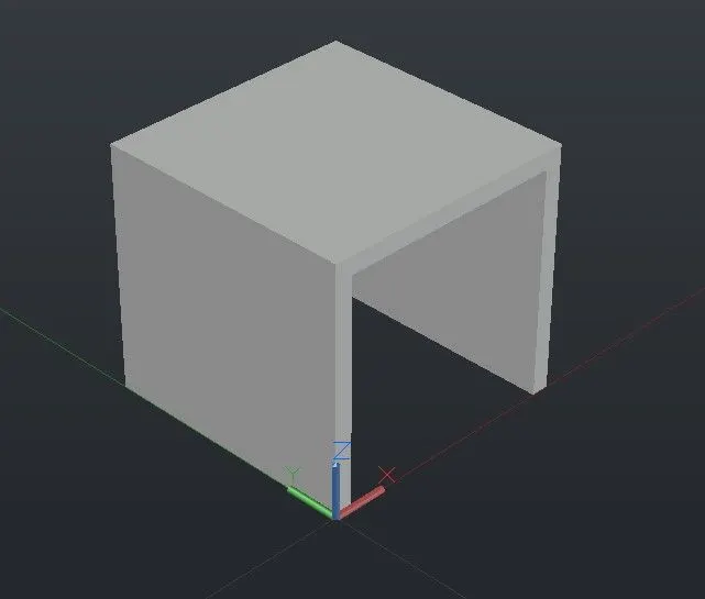
Step 8:Enter union command and select the elements
RESULT
AIM
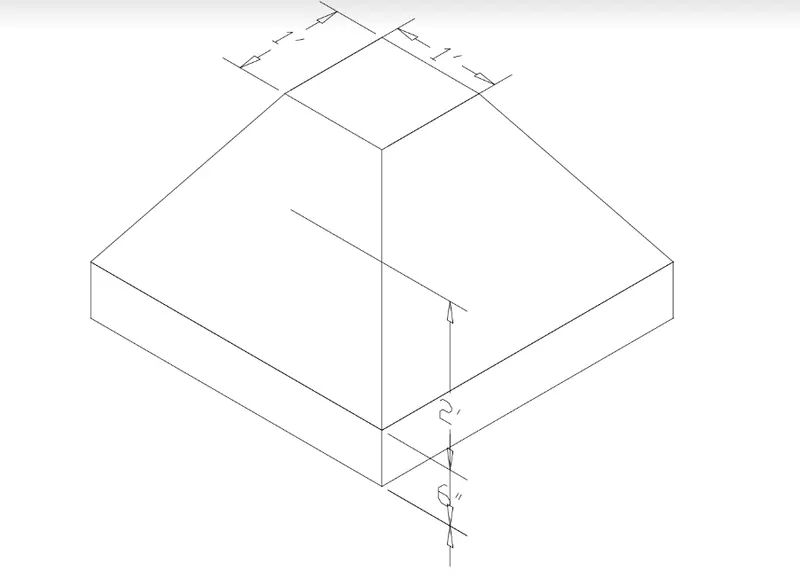
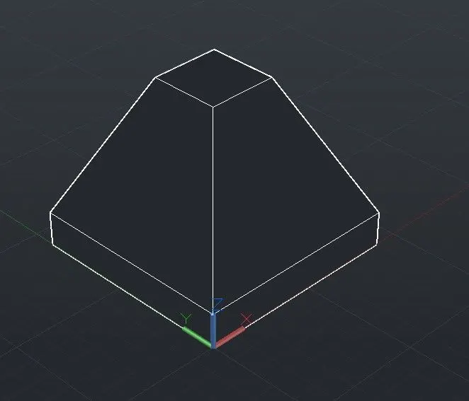
To create the 3d Model of an Isolated footing as shown in Figure
INTRODUCTION
Here we are using 3D modeling in AutoCAD
PROCEDURE
Step 1: Draw the rectangle of size 3’x3’ using coordinate system
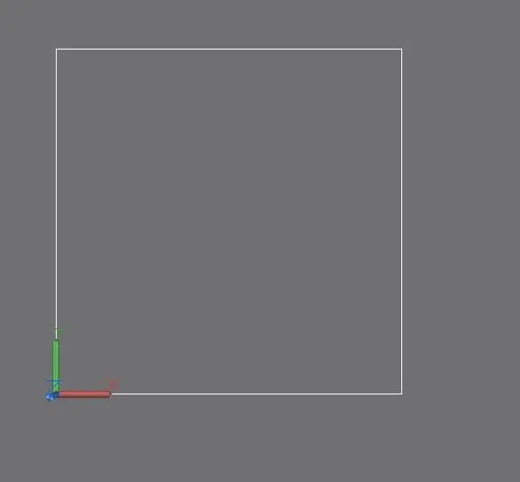
Step 2:Take an offset of 1’
Step 3:Select the rectangle and move upward 6”
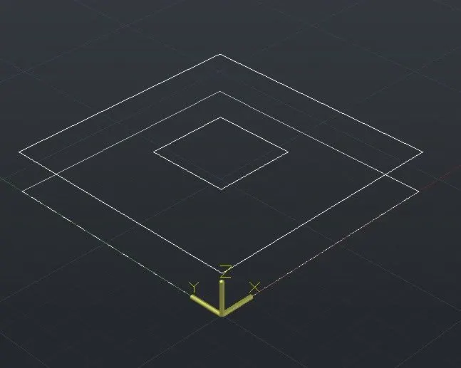
Step 4:Connect the lower rectangle in corners
Step 5:Move upper rectangle 2’
Step 6:Connect the rectangles
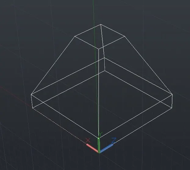
Step 7:Enter ‘3Dface’ command and make faces
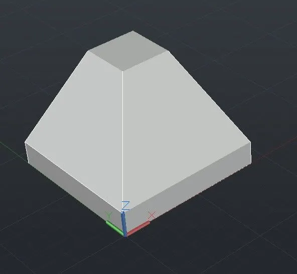
RESULT
AIM
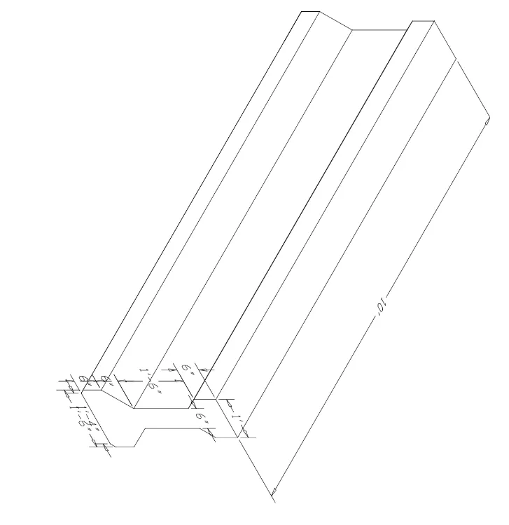
To create the 3D view of the AASTHO Type Girder
INTRODUCTION
Here we are using 3D modeling in AutoCAD
PROCEDURE
Step 1: Draw the plan of the grider using line tool
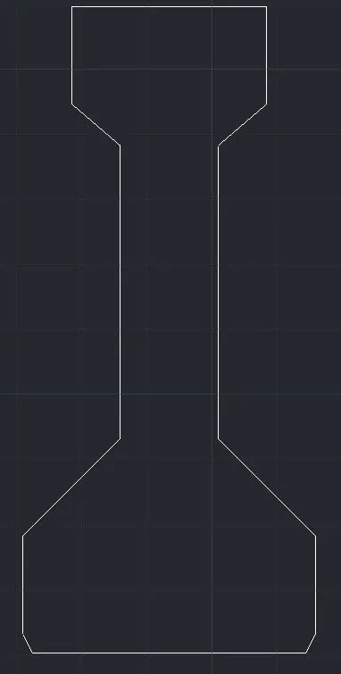
Step 2:Enter region command
Select the region
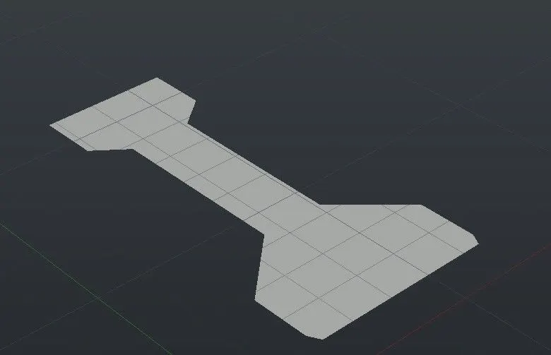
Step 3:Enter extrude command
Select the face
Enter the value 10’
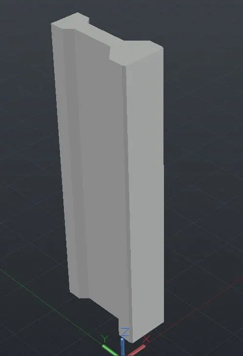
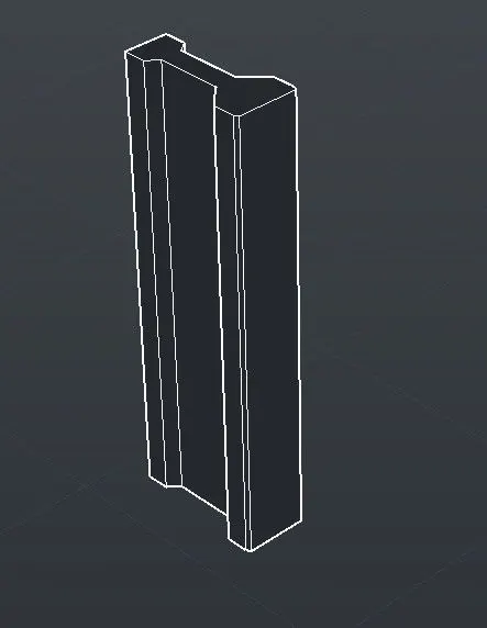
RESULT
AIM
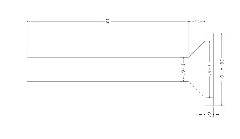
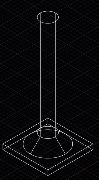
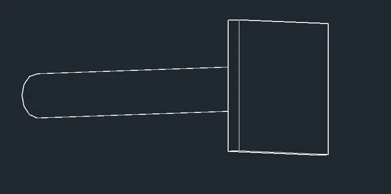
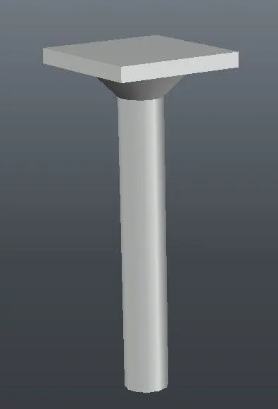
To create a 3d Model of a drop column with panel as shown in section and isometric view
INTRODUCTION
Here we are using 3D modeling in AutoCAD
PROCEDURE
Step 1: Draw the square of size 4’-6” using coordinate system
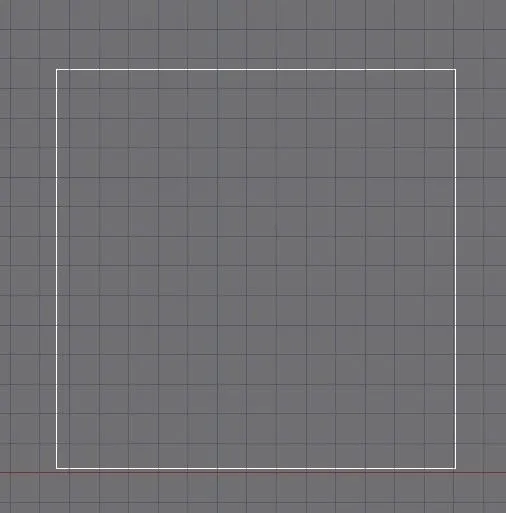
Step 2:Enter region command
Select the region
Step 3:Enter extrude command
Select the face
Enter the value 6”
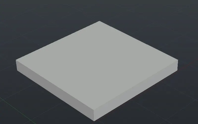
Step 4:Enter cone command
Draw cone of lower circle of dia 3’6”
Upper circle of dia 1’6”
Height 1’
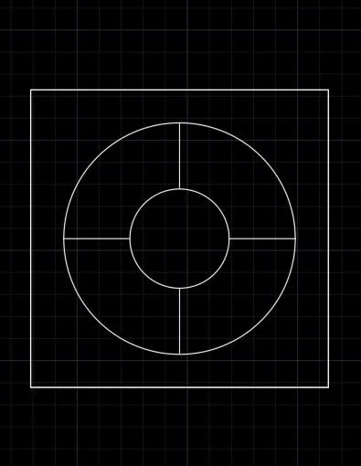
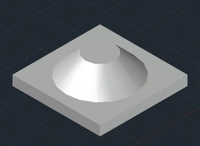
Step 5:Enter presspull command
Select the circle
Give value 10’
Step 6:Enter union command and select the objects
RESULT
AIM
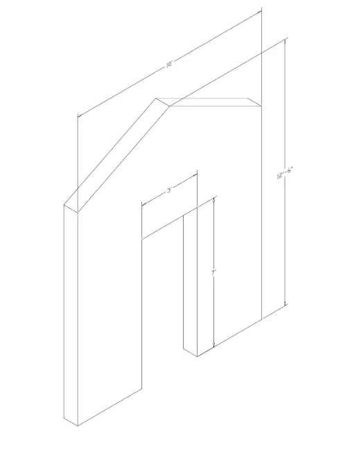
To create the 3d model of a wall as shown in Figure. Consider wall thickness as 9”.
INTRODUCTION
Here we are using 3D modeling in AutoCAD
PROCEDURE
Step 1:Draw the wall using line tool
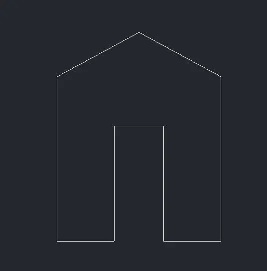
Step 2:Enter region command
Select the region

Step 3:Select the region
Enter extrude command
Enter the value 9”
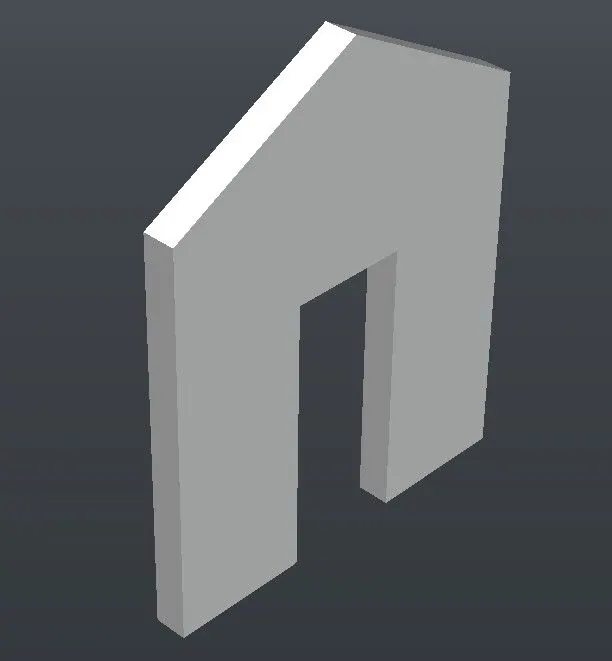
RESULT
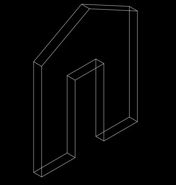
RESULT
Here we studied about the 3d modeling in AutoCAD