Creating various 3D Models like Furniture, Footing, Girder, Column drop with panel and Gable Wall in AutoCad
Aim 1:
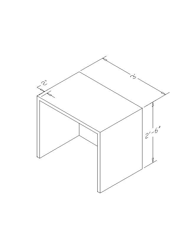
Create a 3D Furniture element as shown in the Figure. Assume dimensions which are missing.
Procedure:
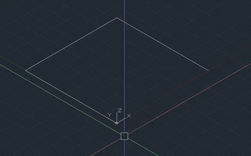
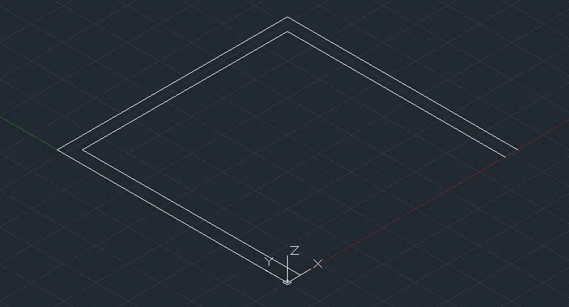
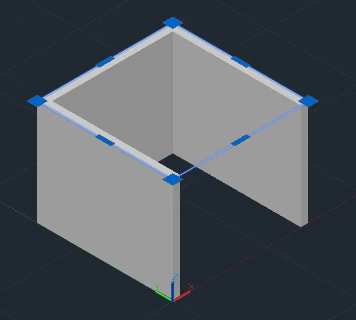
- Draw the lines in CAD as per the given figure.
- line starting point (0,0,0),(@0,3',0),(@3',0,0)&(@0,-3',0). press esc.
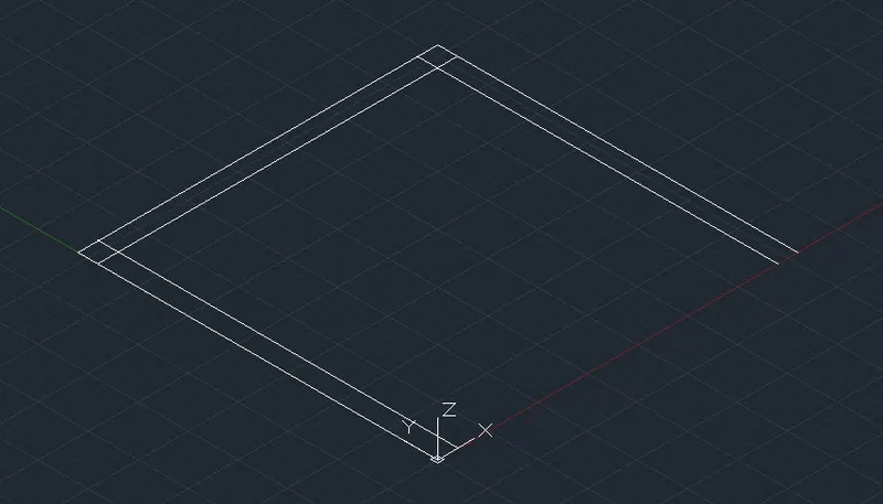
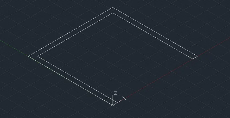
- Enter offset command of value 2" given in figure.
- Fillet the internal lines.
- now close the front openings of the figure.
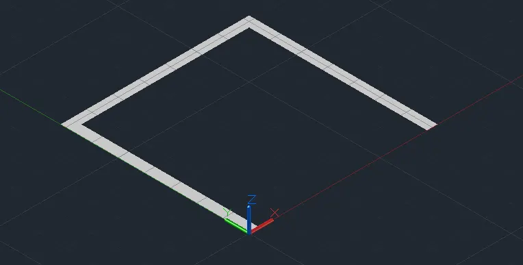
- Now define the region of the closed area.
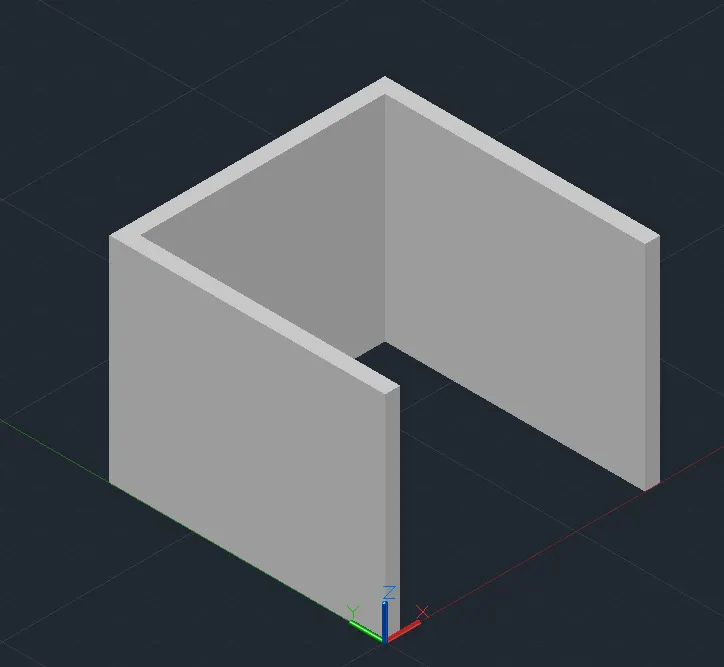
- enter extrude command and extrude the shaded face 2'4" because top is of 2" again.
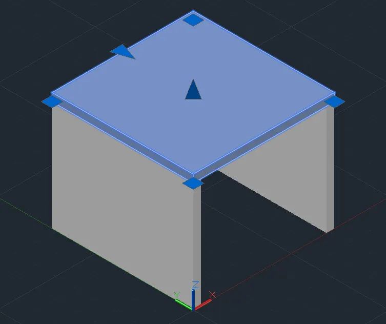
- Now Draw rectangle on the top of the extruded parts.
- Again enter the REGION command and select the rectangle.
- Now enter the EXTRUDE command and extrude the rectangle plate 2".
- Select all side and top extrusion and enter UNION command to make the complete figure.
- Change Shaded workspaces to Hidden.
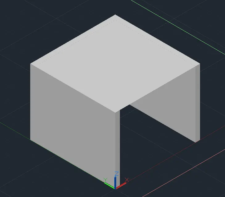
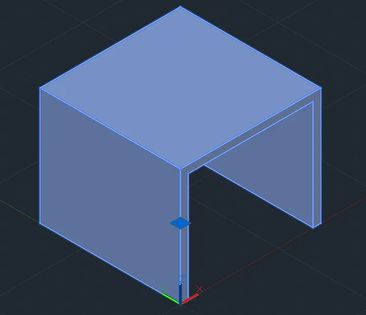
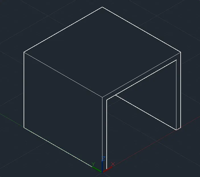
Final Result:
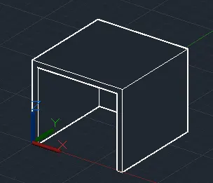
Aim 2:
Create the 3d Model of an Isolated footing as shown in Figure.
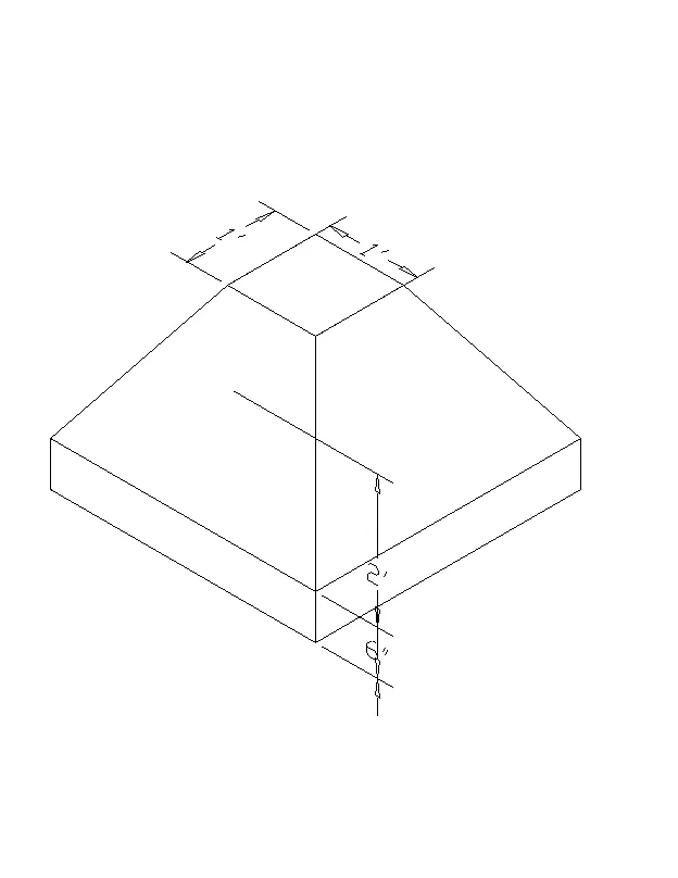
Procedure:
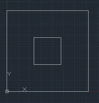
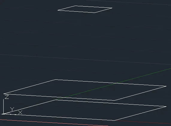
- Draw the 3' x 3' rectangle.
- Make offset of 1' inside.
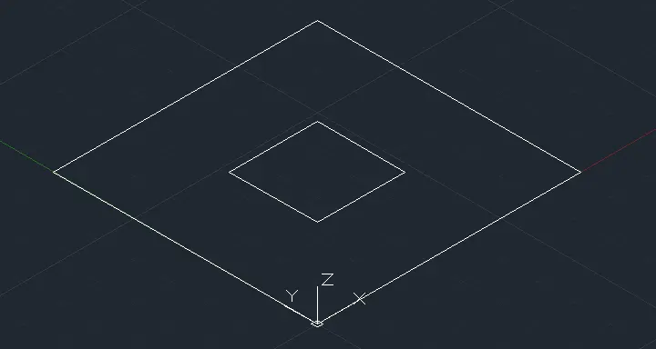
- Open 3D view.
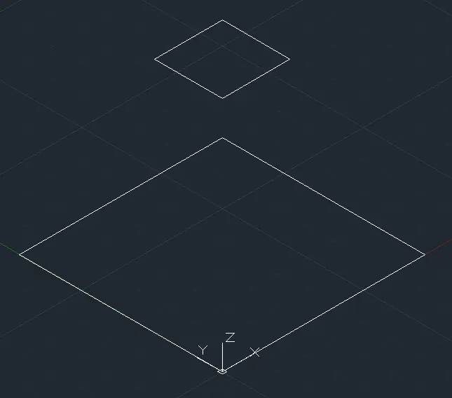
- Now select the middle rectangle ans move it in Z-direction about 2'6".
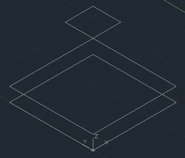
- Make copy of bigger rectangle in Z-direction about 6"
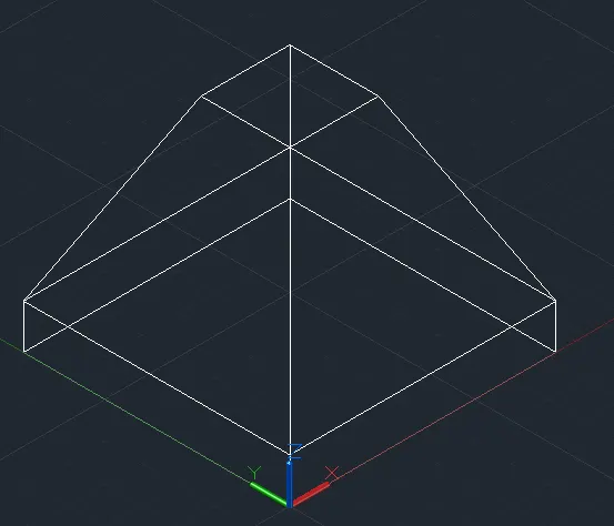
- using Line join all the corners of all three rectangles.
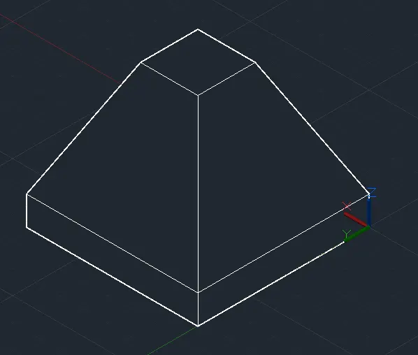
- Now, enter the 3dface command and make the faces as per the given figure.
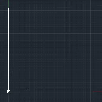
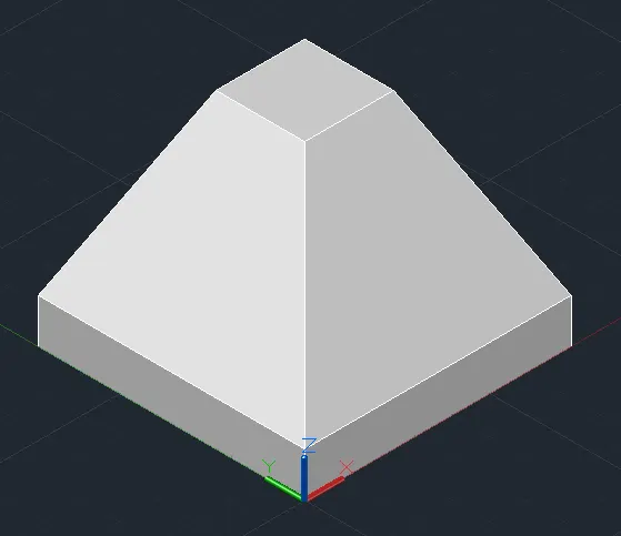
Final Result:
Aim 3:
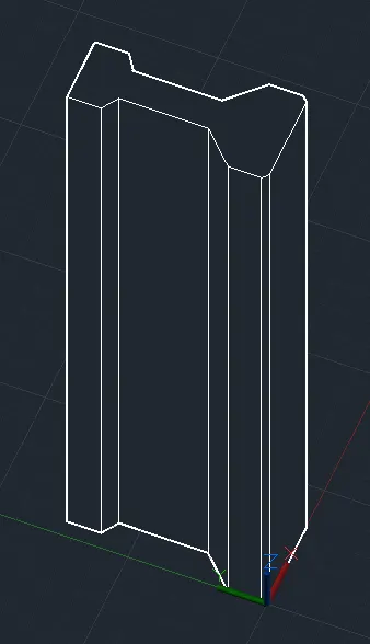
Create the 3D view of the AASTHO Type Girder.
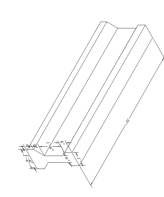
Procedure:
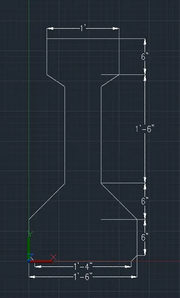
- Draw the section on XY plane as per the given dimensions.
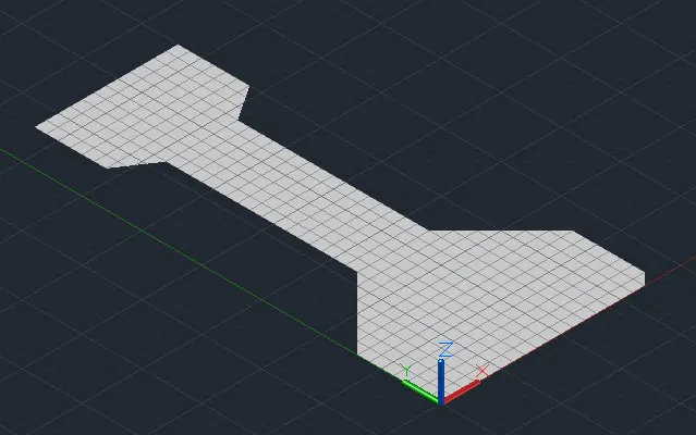
- Enter REGION command and make the section surface.
- Now enter the EXTRUDE command and extrude the face about 10' as per the given figure.
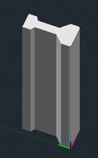
Final Result:
Aim 4:
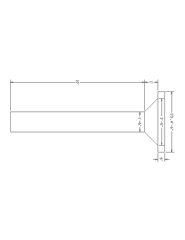
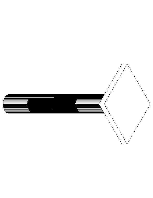
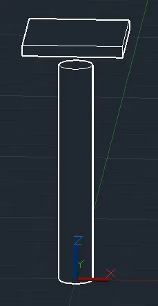
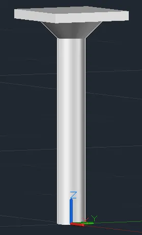
Create a 3d Model of a drop column with panel as shown in section and isometric view.
Procedure:
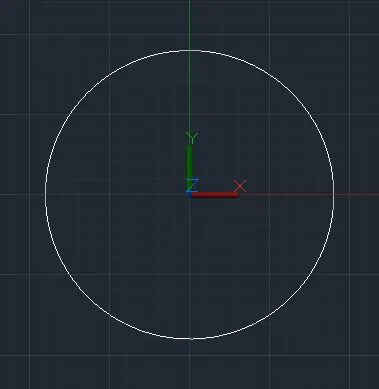
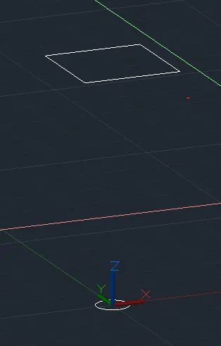
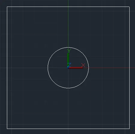
- Draw the Bottom Circle of 1'6".
- Draw the square of 4'6" and move about 11' in Z Direction.
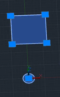
- now region circle and rectangle using REGION command.
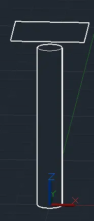
- Enter EXTRUDE and extrude the circle region about 10' Z-direction.
- Enter extrude again and extrude the rectangle about 6".
- Now enter the Cone Command and select the bottom radius and top radius to draw the frustum between rectangle and circle.
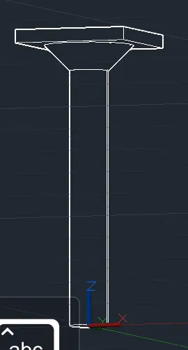
Final Result:
Aim 5:
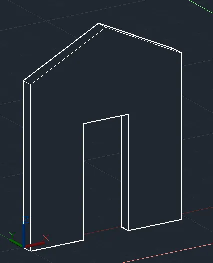
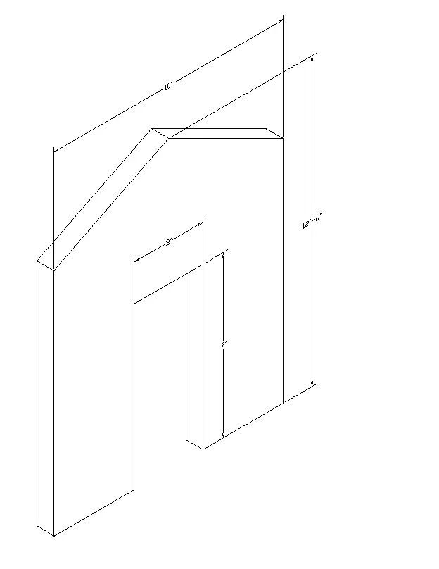
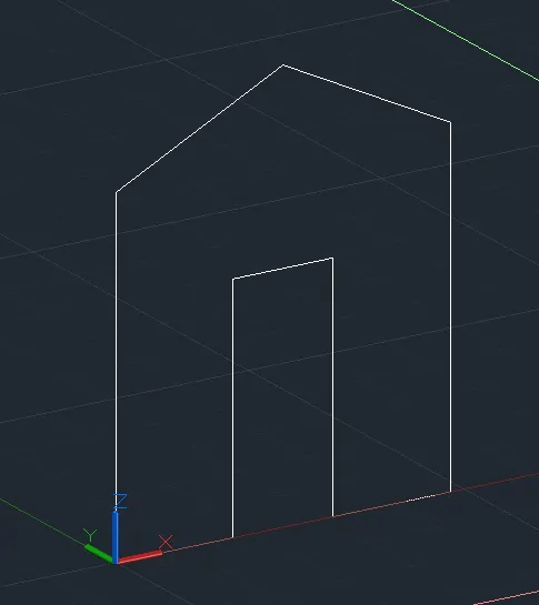
Create the 3d model of a wall as shown in Figure. Consider wall thickness as 9”.
Procedure:
- Draw the section of the Door in XZ-Plan .
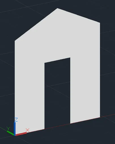
- Enter the region Command and select the section of the figure.
- Enter the EXTRUDE command and extrude the face about 9" as given.
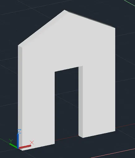
Final Result: