Creating various 3D Models like Furniture, Footing, Girder, Column drop with panel and Gable Wall in AutoCad
Aim-To create a 3D furniture as shown in figure by using Autocad.
Introduction-All dimensions are in feet-inches. Here we are going to show different 3D profile.
Procedure-
-Set sheet in 3D modelling
-Set unit in Engineering, inches
-Set limit and dimension styles
-Draw rectangle of @3',2' make a region and extrude it at a height of 2'6"
-Draw another rectangle at offset of 2" from 1st rectangle
-Subract 2nd rectangle from 1st rectangle by subtract command
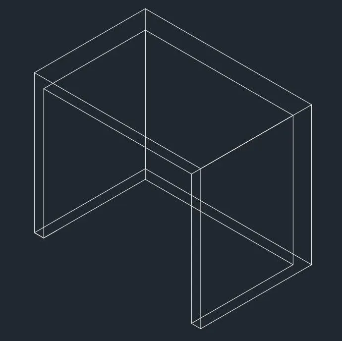
-Now select shaded profile
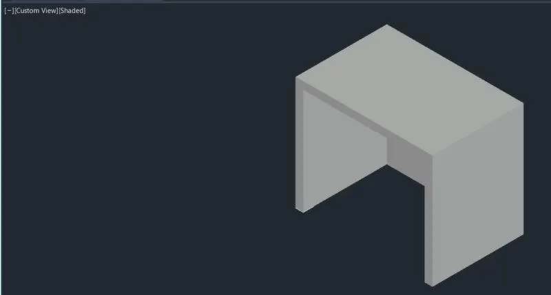
-Now select hidden profile and give dimension
-For dimenion select UCS face according to dimension which we have to given
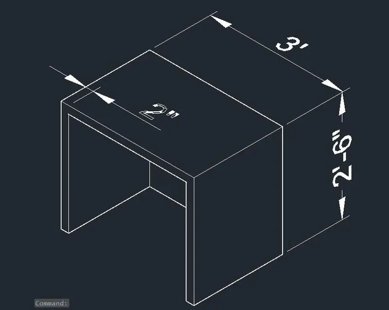
Result-
This is the final sketch of 3D furniture in Autocad
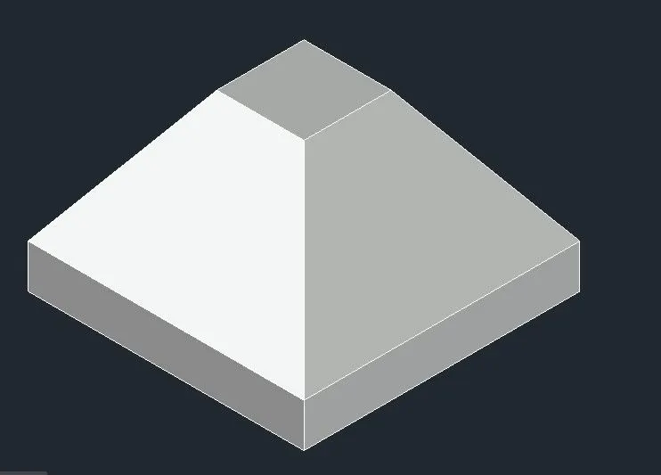
Aim-To create a 3D model of isolate footing as shown in figure.
Introduction-All dimension are in feet and inches.
Procedure-
-Set sheet in 3D modelling
-Set unit in Engineering, inches
-Set limit and dimension styles
-Draw rectangle of @3'2",3'2"and copy it in Z-axis direction 6"
-Join all respective lines
-Draw another rectangle of @1',1' and move it in Z-axis direction 2'
-Join all respective lines
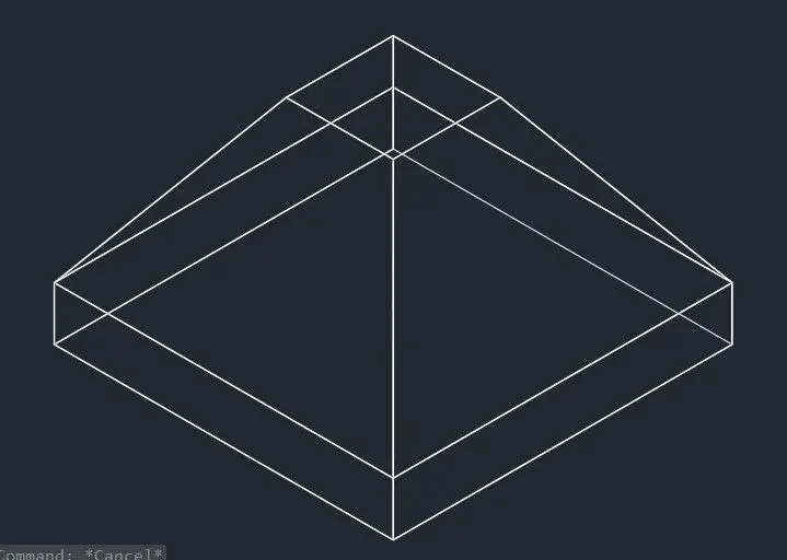
-Draw boundry and make it region and see in it shaded profile
-Now select appropriate UCS face and give dimension to it
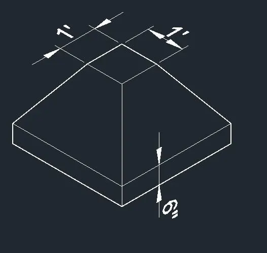
Result-
This is final sketch of isolate footing
Aim-To create a 3D view of AASTHO type girder.
Introduction-All dimension are in feet and inches.
Procedure-
-Set sheet in 3D modelling
-Set unit in Engineering, inches
-Set limit and dimension styles
-By line command start drawing with given dimension
-Fillet with radius 1" whenever necesary
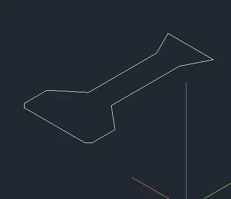
-Now make it boundary and then region
-Now Extrude it with height 10'
-Give dimension with proper UCS face
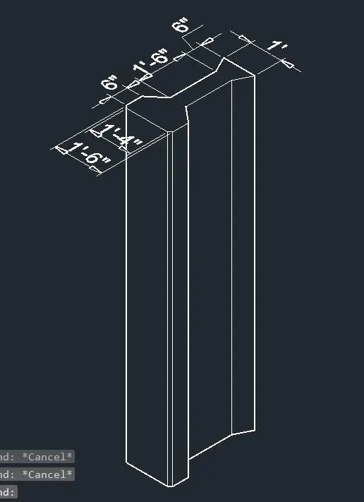
-We can see in various profile shaede, hidden etc whichever required
Result-
This is final sketch of AASTHO type girder by using Autocad,
Aim-To create a 3D model of a drop column with panel as shown in section.
Introduction-All dimension are in feet and inches.
Procedure-
-Set sheet in 3D modelling
-Set unit in Engineering, inches
-Set limit and dimension styles
-Draw a circle of 1'6" make it region and then extrude it with taper angle
-Draw a rectangle of @4'6",4'6" make it region and then extrude it with height 6"
-Now move the circle at center of rectangle
-Again draw a circle of 1'6" make it region and then extrude it with height 10'
-Now this circle move to that 1st circle
-Give dimension properly
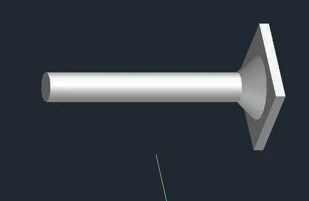
Result-
This is final sketch
Aim-To create a 3D model of wall as shown in figure by using Autocad.
Introduction-All dimension are in feet and inches. Here thickness of wall is 9".
Procedure-
-Set sheet in 3D modelling
-Set unit in Engineering, inches
-Set limit and dimension styles
-Take 3P, polyline and draw a lines according to given sketch
-Then make it region and extrude it 9"
-Now take a line at a mid point of 1st sketch and draw a door according to give sketch by polyline, make it region and extrude it by 9"
-Subtract the door from 1st sketch
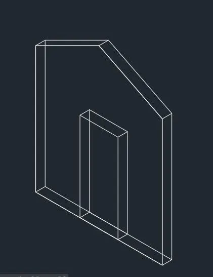
-Set it in hidden profile
-Give dimension by setting UCS properly
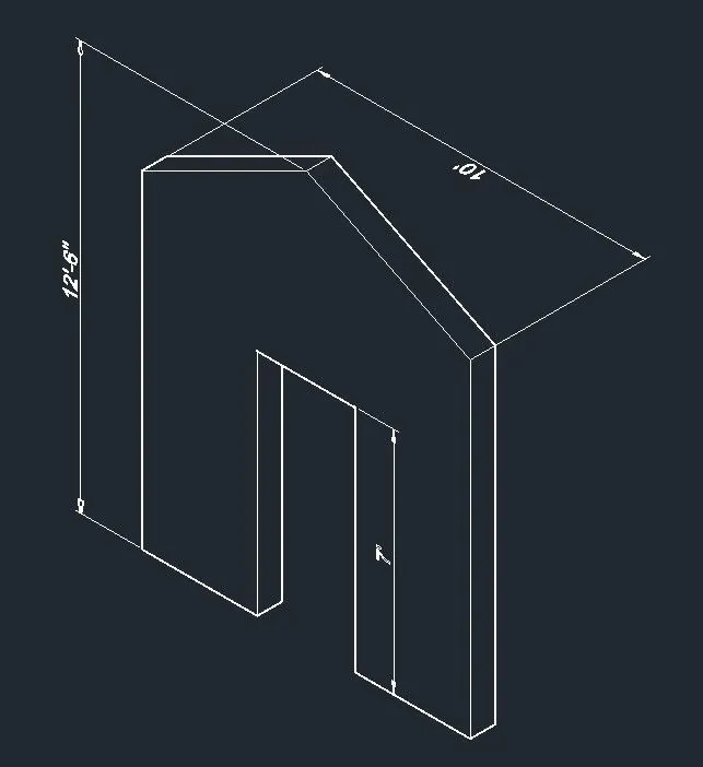
Result-
This is final sketch of 3D model of wall by using Autocad.