Creating various 3D Models like Furniture, Footing, Girder, Column drop with panel and Gable Wall in AutoCad
1.
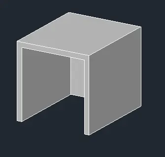
AIM : Create a 3D Furniture element as shown in the Figure.
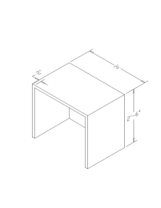
INTRODUCTION : We have Assumed dimensions which are missing. we have used various new command of autocad
PROCEDURE :
- open autocad
- open 3d modelling
- set unit > engineering inches
- select visual style 2d wireframe
- type rec > give dimensions > 3' x 2'6"
- type region > select rectangle
- type extrude > select object > type 2'6" height
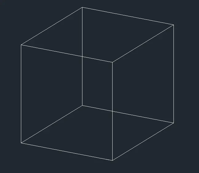
- type ucs and change ucs icon position
- take two reference of 2" to make other rectangle
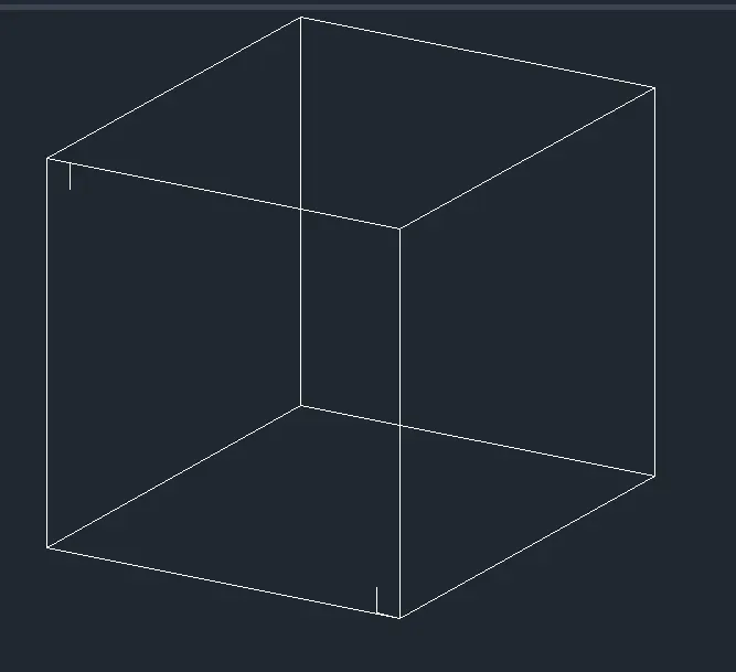
- type rec and make rectangle connecting to this reference line
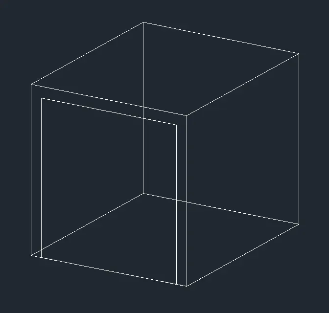
- type extrude > select inner rectangle > give extrude distance of -2'10"
- type subtract > select outer rectangle > select inner rectangle > press enter
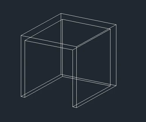
- select hidden visual style
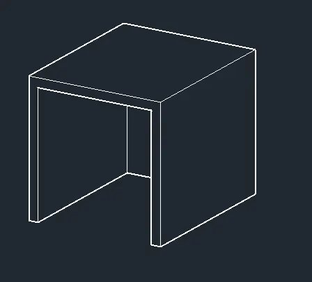
RESULT :
We have Created a 3D Furniture element as shown in the Figure.
2.
AIM :
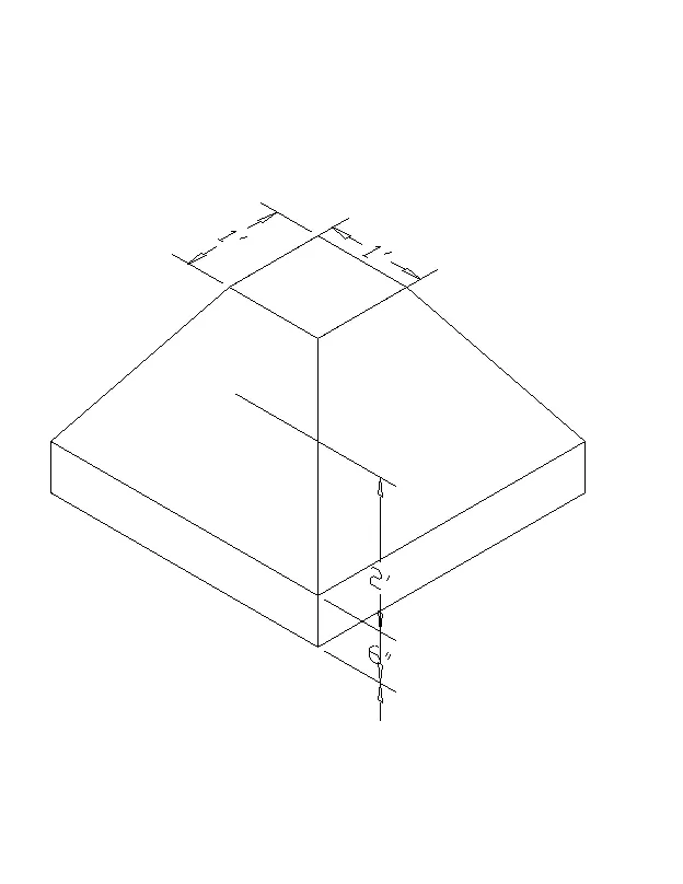
Create the 3d Model of an Isolated footing as shown in Figure
INTRODUCTION:
We have drawn part of isolated footing. we have used extrude and loft command in this drawing.
PROCEDURE :
- open autocad
- open 3d modelling
- set unit > engineering inches
- select visual style 2d wireframe
- type rec > give dimensions > 3' x 3'
- type offset > give ofset of 1' to rectangle
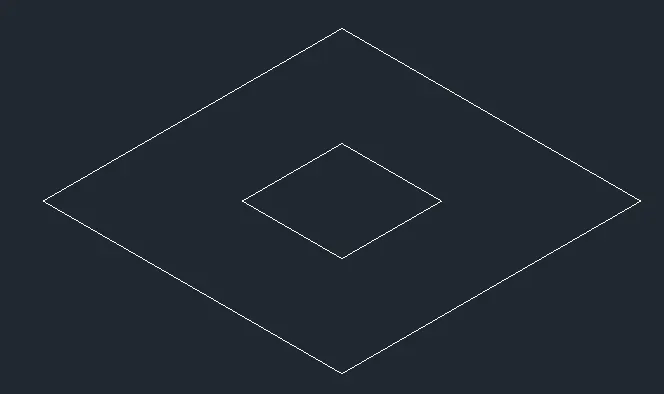
- type move and move the inner rectangle upward 2' distance
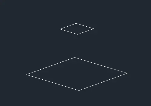
- select loft command > select 2 object to loft
- select bottom plane and extrude it
- extrude > select object > type -6" > enter
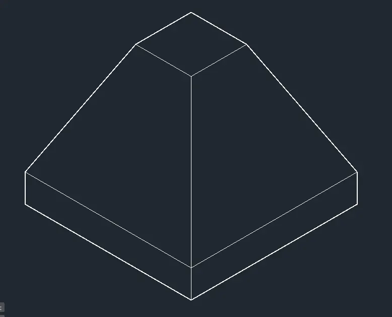
- Type ucs > set the ucs direction
- type dimlin > give the dimension
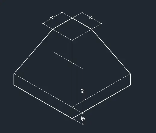
RESULT :
Create the 3d Model of an Isolated footing as shown in Figure.
3.
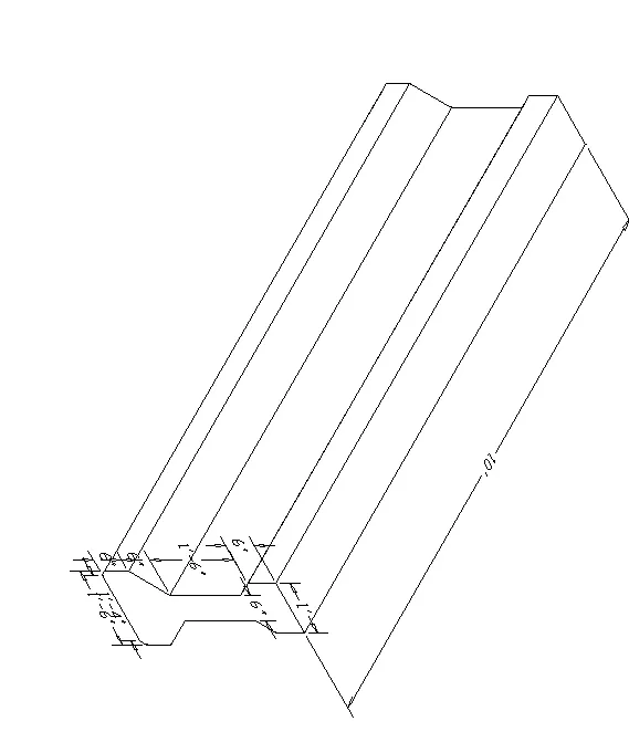
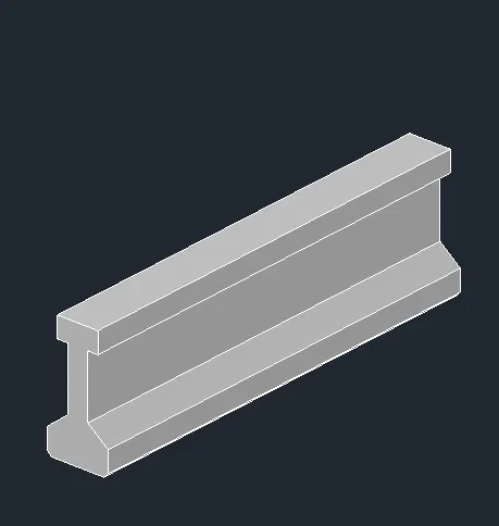
AIM: Create the 3D view of the AASTHO Type Girder
INTRODUCTION:
We have drawn AASTHO type girder using etrude and region command
PROCEDURE :
- open autocad
- open 3d modelling
- set unit > engineering inches
- select visual style 2d wireframe
- select proper position of ucs
- select line command > make line to y direction 1'
- give line command to both corner point of line
- make 6" line to down z direction
- calculate the other distance make dig as shown
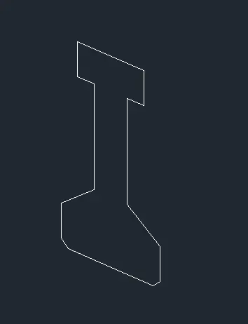
- type region command > select the above object
- type extrude command > select object > give extrude distance 10'
- select hidden visual style
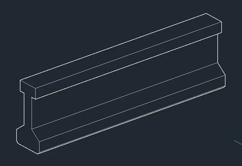
- Type ucs > set the ucs direction
- type dimlin > give the dimension
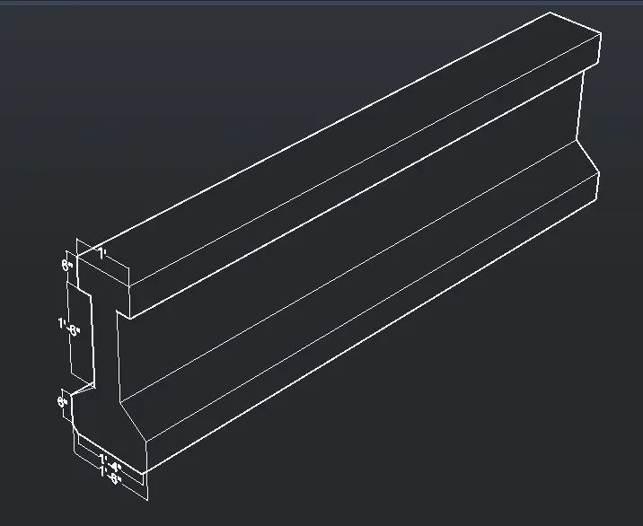
RESULT :
We have Created the 3D view of the AASTHO Type Girder
4.
AIM :
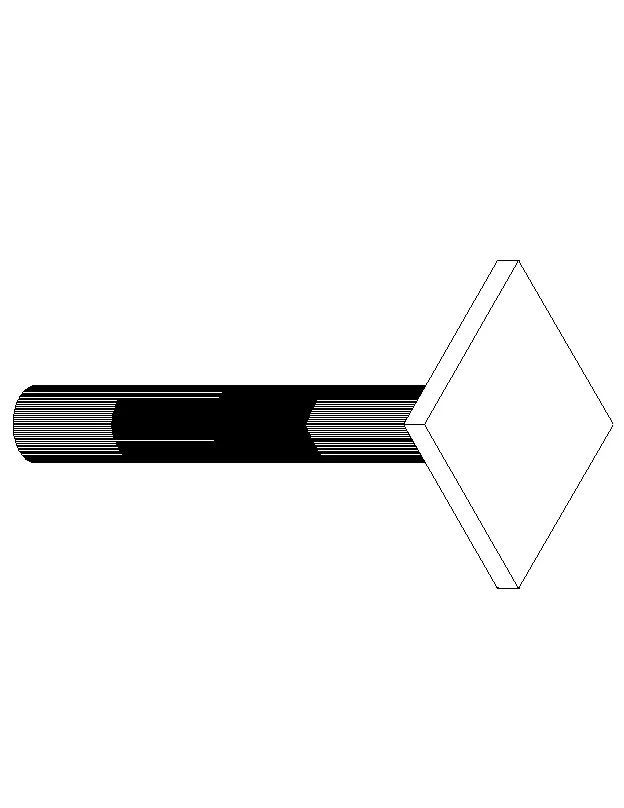
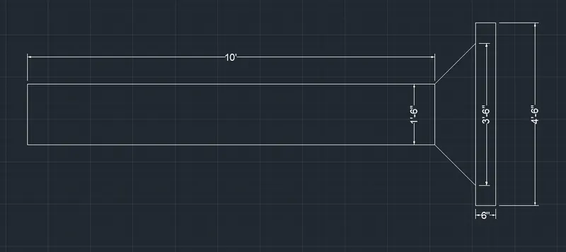
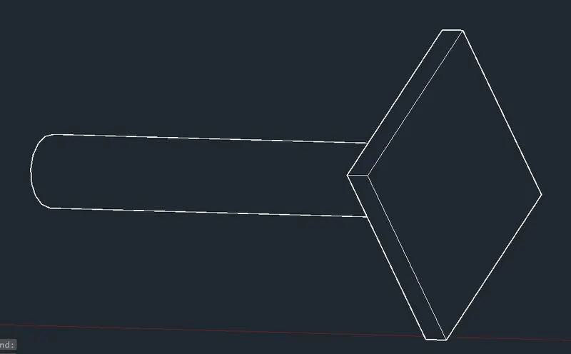
Create a 3d Model of a drop column with panel as shown in section and isometric view.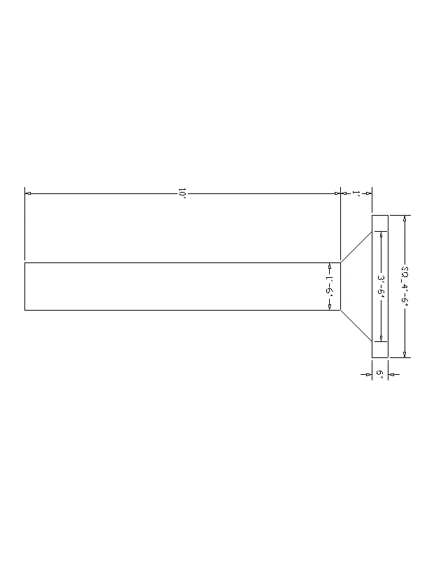
INTRODUCTION :
we have drawn 3d model of drop column with panel and isometric view using various command in autocad .
PROCEDURE :
- open autocad
- open 3d modelling
- set unit > engineering inches
- select visual style 2d wireframe
- type line > draw a line 4'6" > then line of 6" both the corner point and join the line
- take reference of middle point > draw a line of 3'6"
- draw other line using dimension given
- type dimlin and give dimension
- type boundry > pick point > select object >enter
- type region > select object > enter
- type extrude > select object > extrude distance 4'6"
- for inclied digram 3'6'"
- set the ucs
- draw a circle to centre of 1'6" position
- extrude > select object > distance 10'
- Type ucs > set the ucs direction
- type dimlin > give the dimension
RESULT :
we have Created a 3d Model of a drop column with panel as shown in section and isometric view.
5.
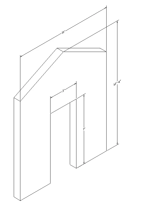
AIM :Create the 3d model of a wall as shown in Figure. Consider wall thickness as 9”
INTRODUCTION :
we have Created the 3d model of a wall as shown in Figure. we have Considered wall thickness as 9”. we have used extrude command to give thickness.
PROCEDURE :
- open autocad
- open 3d modelling
- set unit > engineering inches
- select visual style 2d wireframe
- type line
- make line 3.5'> make line in z direction 7'> then3' line to xdirction> then 7' down>then 3.5' in xdirction
- then 10' line to z dirction upward> draw a line from middle 12'6" which is reference line
- join 10' line to 12'6" line
- do similarly from other side
- erase reference line
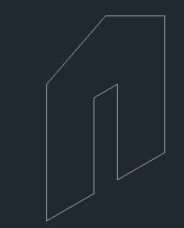
- type boundry > pick point > select object >enter
- type region > select object > enter
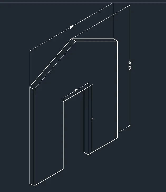
- type extrude > select object > give distance 9"
- Type ucs > set the ucs direction
- type dimlin > give the dimension
RESULT :
Create the 3d model of a wall as shown in Figure. Consider wall thickness as 9”.