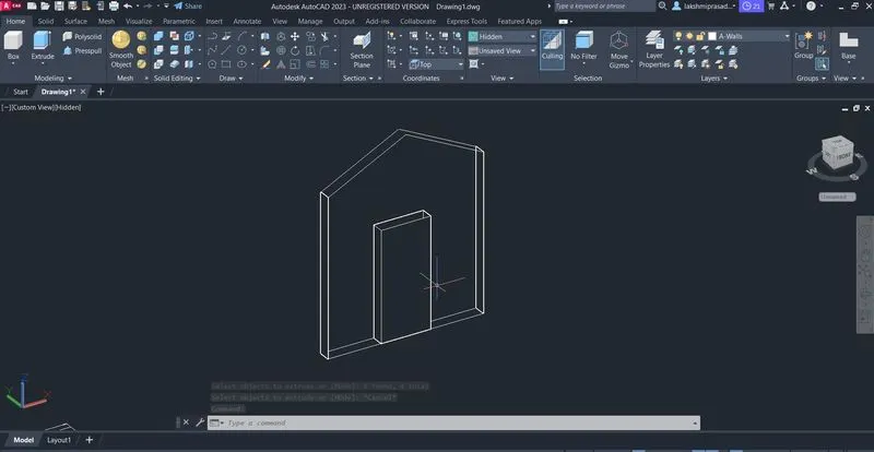
Creating various 3D Models like Furniture, Footing, Girder, Column drop with panel and Gable Wall in AutoCad
1. Create a 3D Furniture element as shown in the Figure. Assume dimensions which are missing.
Command used:
1. Rectangle tool
2.Extrude
3.subtract
4. UCS
5.Box
6. Offset
7.Move
8.Sweep
9.Cone
10Region.
11. Boundary.
Procedure: Open auto cad.
set the units as imperical
units set to engineering with predcision 0'0"
set the limax as 100,100
zoom command - all , set the page.
from the setting switch to 3d modelling.
set to top view - wire frame.
draw a rec of dimension 3'x3' in xy-plane.
explode the rectangle.
offset 3 side at distance 2".
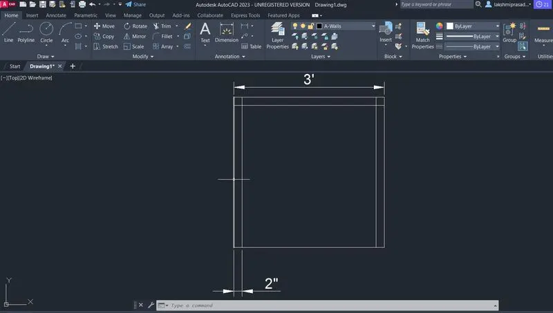
enter boundary command and select offset lines,make a region.
similarly repeat the same for other two sidesand whole rectangle.
go to default view by cliking on home button.
select extrude from ribbon and select all region.
extrude at height in z-axis as 2'6".
select subract command select the rectangle- enter.
select smaller rec - enter.
select union command and select all objects enter.
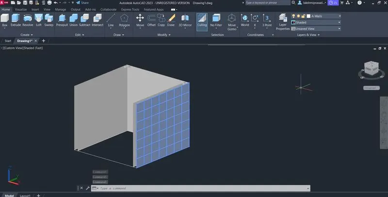
use liner dimension and measure by switching ucs.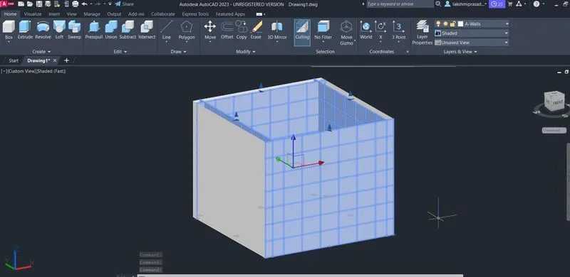
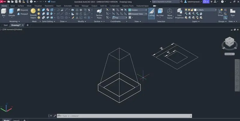
2.2. Create the 3d Model of an Isolated footing as shown in Figure.
Ans:Given footing an isolated footing/tapeering footing of dimension 1' x1' at the top and 2'x2'. at bottom width at 6" pcc bed.
command used here is tapering option box command.
Procedure: set the view to top and second wire frame.
Draw a rec of each side to 2inches.
select offset command,select rec and enter the distance as 1'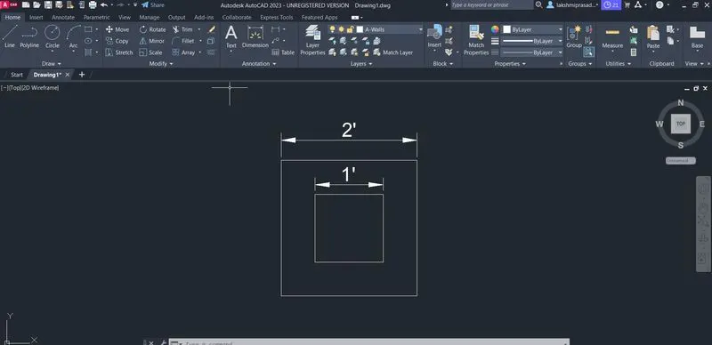
Move todefault view
enter move command , 1'x1' rec and move it a distance of 3'.
select loft command, select two rec and enter.
now extrude the rec size of 2'x2' with ht 6".
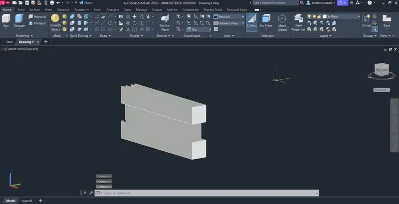
3.Create the 3D view of the AASTHO Type Girder.
Intoduction : Aastho type of girder, which has expanded the width of upper and lower flange..
these types are mainly used in bridge construction.
Procedure: set the view to top and wire frame.
Draw a set of rec and dimension of 10' x6" ,10' x 1'4",10'x1'6" and 10'x1'.
Now allign the rec in bigger rectangle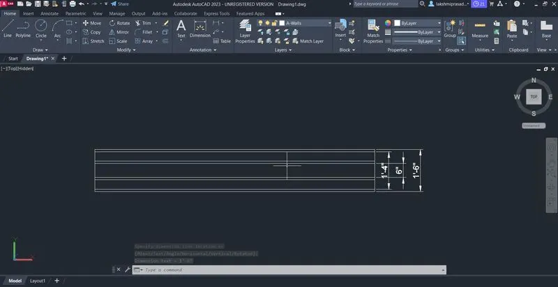
set the view to sw isometric .
extrude the rec upto given heights, for ex for 10'x6", extrude upto ht 1'6".
follow the saje of remaining.
Allign the rec upto certain ht using move command, example move rec 10'x6" at height 0,0,1'
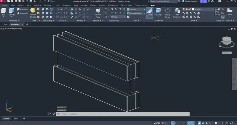
Now tamper last second rec by selecting width face, specify base point and axis and entire angle as 15.
similarly for second rec enter angle as 45.
use union command to join the extrude the section.
4. Create a 3d Model of a drop column with panel as shown in section and isometric view.
Procedure: select the top view with wire frame.
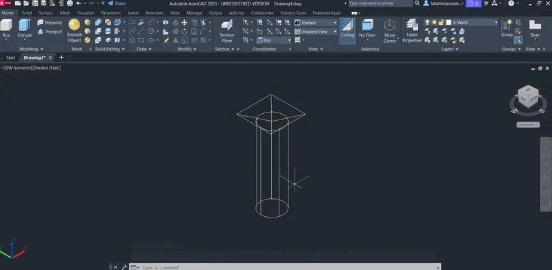
draw a circle of dia 1'6".
extrude the circle at height 10' in the default view.
move the back t top viewand draw a rec of sides 3'6".
place the rec on circle usng onsnap or enter distance 0,0,10.
Extrude enter rec at ht 1'.
select chamfer command from solid edit tool and select the face.
specify the base point and enter angle as 45 degree.
repeat the same on other side or use loop/ chain command in champer.
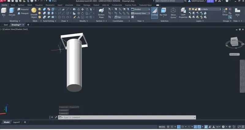
back to top view and draw rec of side 4'6".
move back to isometric viewand extrude at height 6".
place the rec on top of 3'6" on rec using ucs icon. or distance command.
usc union to make object 1.
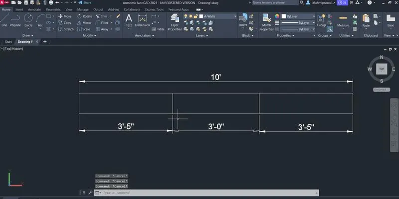
Enter bo command- select the point -convert to region.
set the view to default isometric.
extrude the corner region upto ht 12'6".
now move the door rec to height 0,0,7'
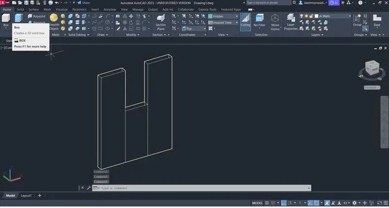
Now extrude the move rec upto 12.5'
set the view to front and draw arec of sides5.5' and base 10'.
make triangles as region using boundary command.
extrude the triangel distance 9" towards y-axizx.
use grip to reduce the rec wall.
use union command to join all extruded walls.