Creating various 3D Models like Furniture, Footing, Girder, Column drop with panel and Gable Wall in AutoCad
Creating various 3D Models like Furniture, Footing, Girder, Column drop with panel and Gable Wall in AutoCad
Q-1:-
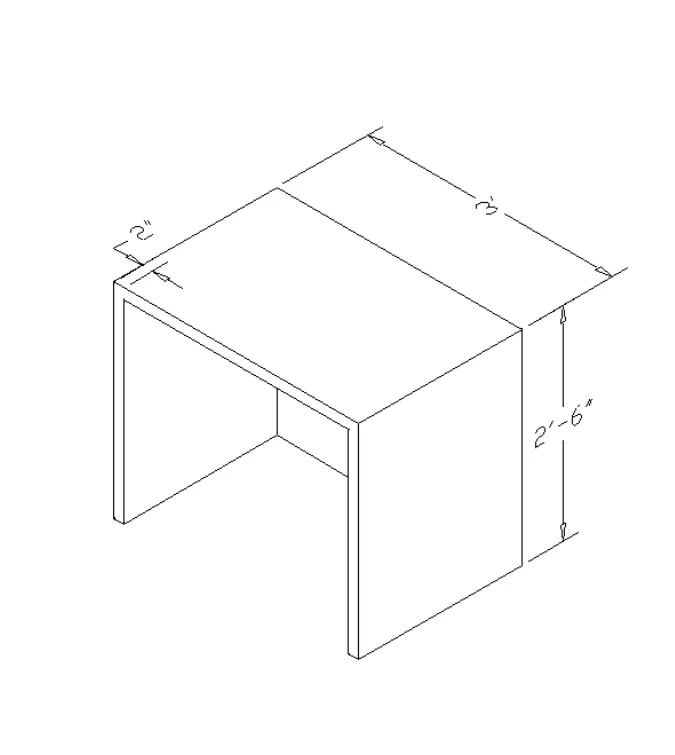
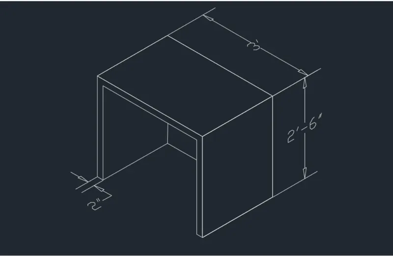
Create a 3D Furniture element as shown in the Figure.
Aim:
To create a 3D Furniture element as shown in the figure above in AutoCAD.
Introduction:
The 3D furniture is created in AutoCAD in 3D Modelling workspace using primarily the line tool. The procedure of drawing is explained in detail with diagrams of each step and the final result is given.
Procedure:
STEP1
- Go to START MENU, select AutoCAD 2022
- In the Command line type in: STARTUP [ENTER]
- Enter new value of startup: 1
- Go to Application Menu and select New
- Select Imperial, click OK.
- Enter UNITS command in the command tab.
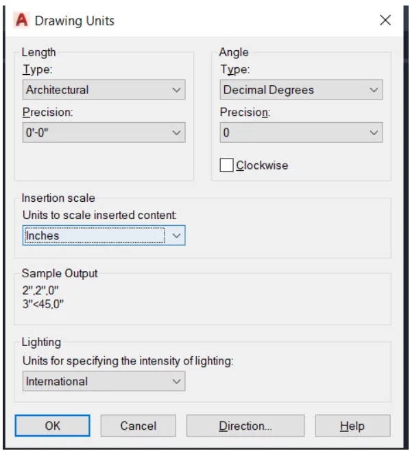
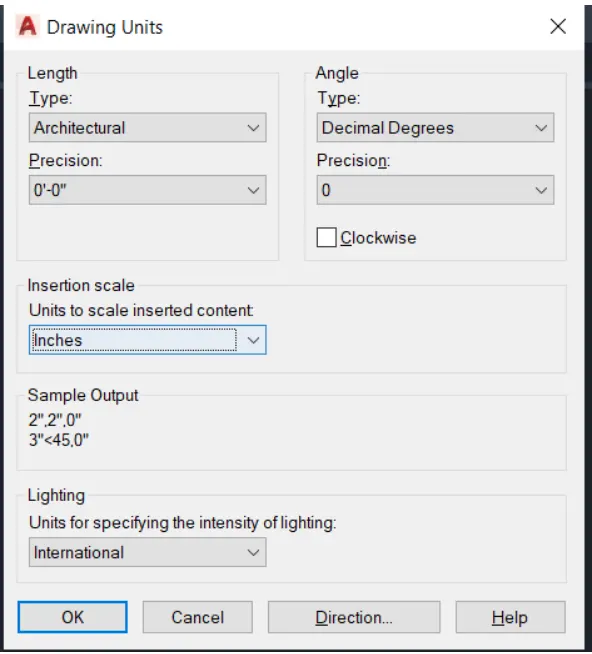
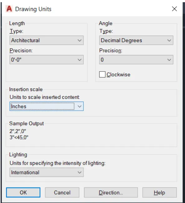
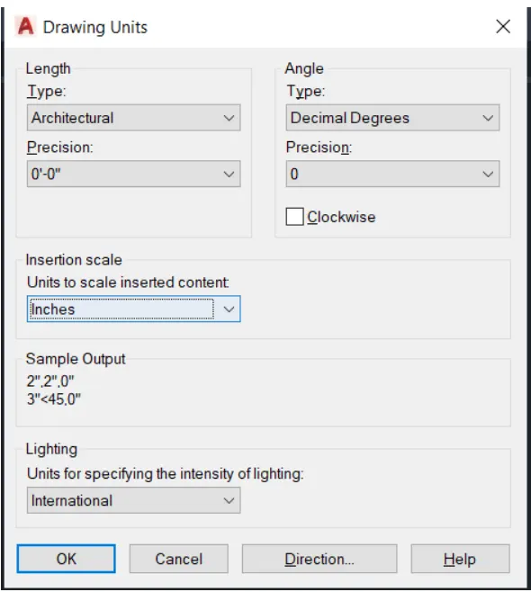
- In the Drawing Units dialog box, select Architectural in Type; 0-0.0" in Precision; and 'Inches in Insertion scale
- Click on OK
- Select 3D Modelling from the Workspace Switching drop down list.
- Set the limits by entering LIMITS in the Command tab. The lower-left corner is specified as 0'0.0",0'0.0", and the upper-right corner is specified as 100',100
- Enter 3DORBIT in the command line.
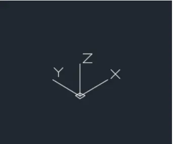
- Change the UCS view.
- Press Esc.
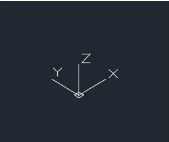
STEP 2
- Select the Line tool by entering 'LINE' command in the command tab.
- Specify the first point as 0,0,0 in the command line.
- Specify the coordinate of next point as @0,0,2'6" in the command line.
- Specify the coordinate of next point as @0,3',0 in the command line.
- Specify the coordinate of next point as @0,-2",0 in the command line.
- Specify the coordinate of next point as @0,0,2'4" in the command line.
- Specify the coordinate of next point as @0,-2'8",0 in the command line.
- Specify the coordinate of next point as @0,0,-2'4" in the command line.
- Specify the coordinate of next point as @0,-2",0 in the command line.
- Press Esc.
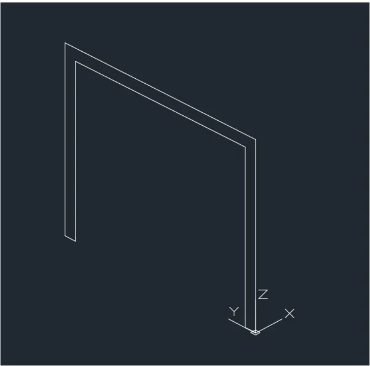
STEP 3
- Select the Line tool by entering 'LINE' command in the command tab.
- Select the first point as the top left corner of the box. Specify the coordinate of next point as @2',0,0 in the command line.
- Specify the coordinate of next point as @0,-3,0 in the command line.
- Specify the coordinate of next point as @0,0,-2'6" in the command line.
- Specify the coordinate of next point as @-2,0,0 in the command line.
- Press Esc.
- Select the Line tool by entering 'LINE' command in the command tab.
- Draw lines to connect the corners of the 3D box.
- Press Esc.
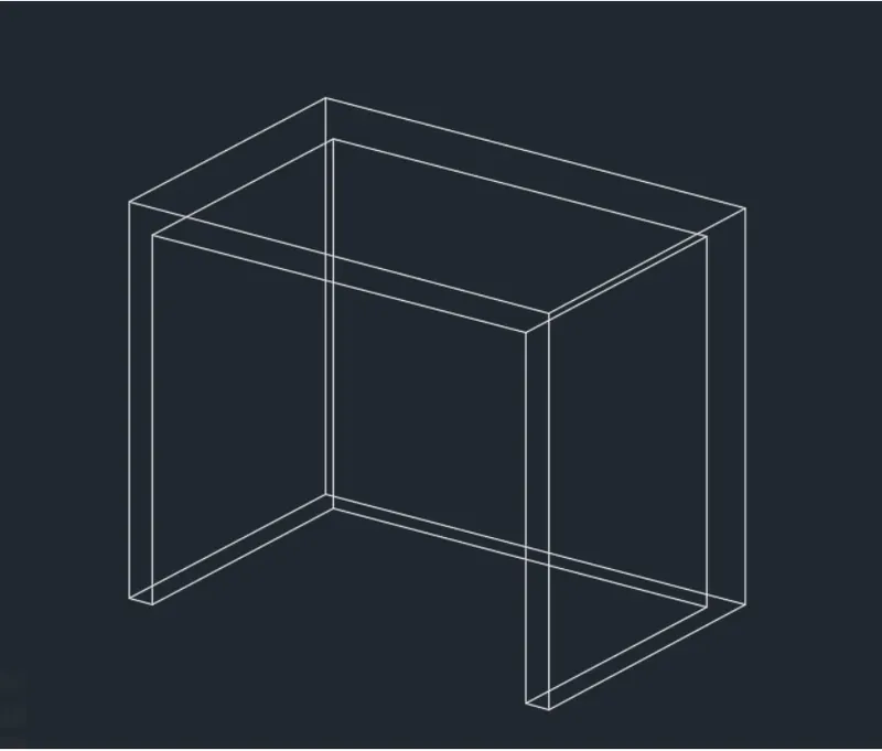
STEP 4
- Enter 3DFACE command in the command tab.
- Draw four point faces covering all sides of the box.
- Press Esc.
- Enter HIDE in the command line.
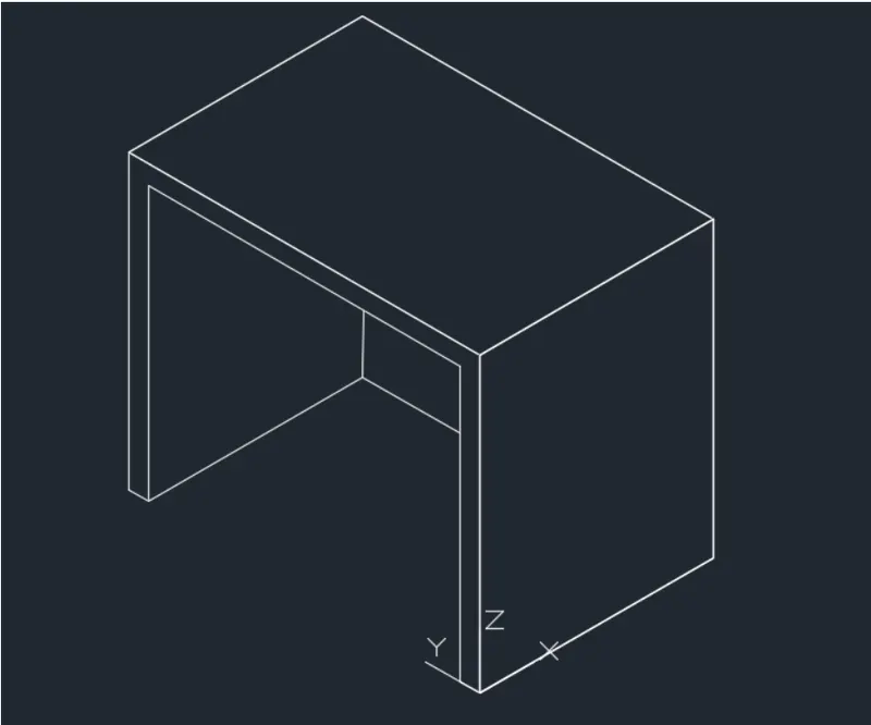
STEP 5
- Enter DST command in the command tab to open the Dimension Style Manager dialog box.
- Click on the Modify tab.
- Under the Lines option change the colour of the dimension and extension lines.
- Under the Symbols and Arrows option change the Arrow size to 3".
- Under the Text option change the Text height to 3".
- Click OK. Then click on Set Current and Close the dialog box.
- Go to Annotate, select DIMLINEAR tool.
- Select the first point and second point of the object to be measured, then drag the dimension line to the desired location. Repeat for all the objects to be measured.
- Save the drawing.
RESULT:
Q-2:-
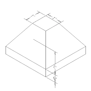
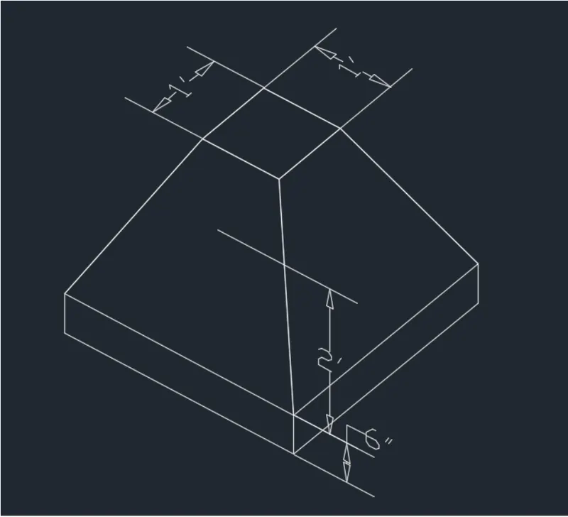
Create the 3d Model of an Isolated footing as shown in Figure.
Aim:
To create the 3D Model of an Isolated Footing as shown in the figure above in AutoCAD.
Introduction:
The 3D Model of the Isolated Footing is created in AutoCAD in 3D Modelling workspace using primarily the line and rectangle tools. The procedure of drawing is explained in detail with diagrams of each step and the final result is given.
Procedure:
STEP1
- Go to START MENU, select AutoCAD 2022
- In the Command line type in: STARTUP (ENTER]
- Enter new value of startup: 1
- Go to Application Menu and select New
- Select Imperial, click OK.
- Enter UNITS command in the command tab.
- In the Drawing Units dialog box, select Architectural in Type; 0-0.0" In Precision; and Inches' in Insertion scale.
- Click on OK.
- Select 3D Modelling from the Workspace Switching drop down list.
- Set the limits by entering LIMITS in the Command tab. The lower-left corner is specified as 0'0.0",0'0.0"; and the upper-right corner is specified as 100',100'
- Enter 3DORBIT in the command line.
- Change the UCS view.
- Press Esc.
STEP 2
- Select the Rectangle tool by entering REC command in the command tab.
- Specify the first point as 0,0,0 in the command line.
- Specify dimension as @3',3"
- Again select the Rectangle tool.
- Specify the start point.
- Specify dimension as @1',1"
- Select the smaller rectangle and Move it in such as way that its center coincides with the centre of the larger
- rectangle.
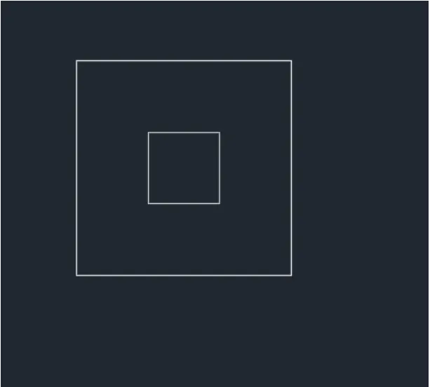
STEP 3
- Select the Smaller Rectangle of size TXI, and move it to a distance of 26" in the positive z direction (+2 axis)..
- Select the Extrude tool from the Ribbon and extrude the rectangle of size 3x3 to a height of 6"
- Select the Line tool by entering LINE command in the command tab
- Draw lines connecting all the corners of the top rectangle and the base cuboid.
- Press Esc.
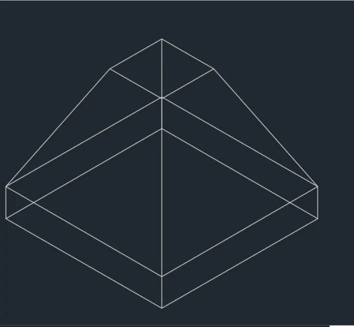
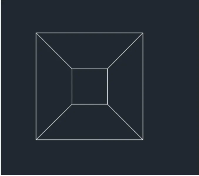
STEP 4
Enter 3DFACE command in the command tab.
Draw four point faces covering all sides of the isolated footing.
Press Esc.
Enter HIDE in the command line.
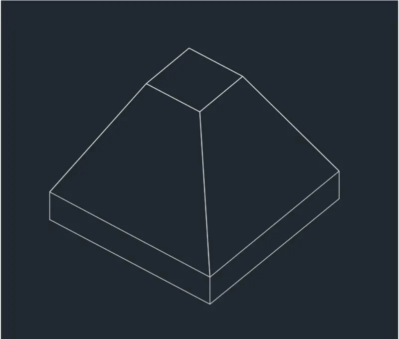
STEP 5
- Enter 'DST command in the command tab to open the Dimension Style Manager dialog box.
- Click on the Modify tab.
- Under the Lines option change the colour of the dimension and extension lines.
- Under the Symbols and Arrows option change the Arrow size to 3".
- Under the Text option change the Text height to 3".
- Click OK. Then click on Set Current and Close the dialog box.
- Select, move and place the UCS in a way such that the X-Y plane is positioned where the dimension is required.
- Go to Annotate, select DIMLINEAR tool.
- Select the first point and second point of the object to be measured, then drag the dimension line to the desired location. Repeat for all the objects to be measured.
- Save the drawing.
RESULT:
Q-3:-
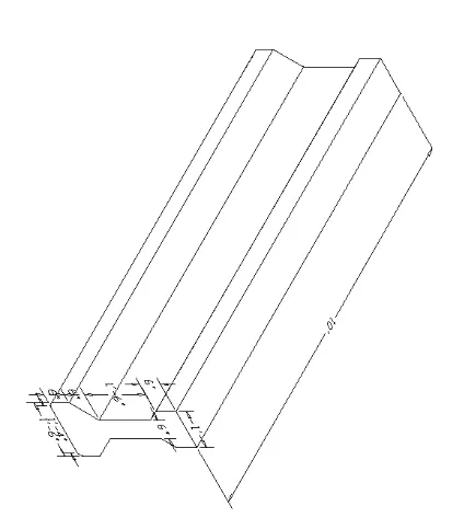
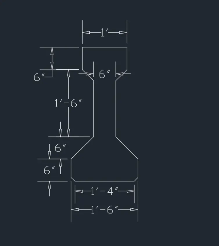
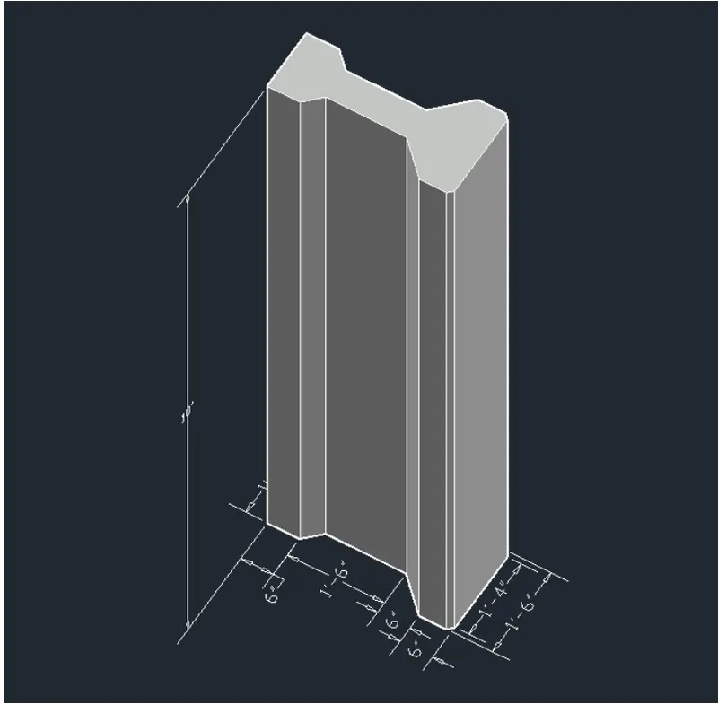
Create the 3D view of the AASTHO Type Girder.
Aim:
To create the 3D view of the AASTHO Type Girder as shown in the figure above in AutoCAD.
Introduction: The 3D view of the AASTHO Type Girder is created in AutoCAD in 3D Modelling workspace using primarily the line tool. The procedure of drawing is explained in detail with diagrams of each step and the final result is given
Procedure:
STEP1
- Go to START MENU, select AutoCAD 2022
- In the Command line type in: STARTUP [ENTER]
- Enter new value of startup: 1
- Go to Application Menu and select New
- Select Imperial, click OK.
- Enter UNITS command in the command tab.
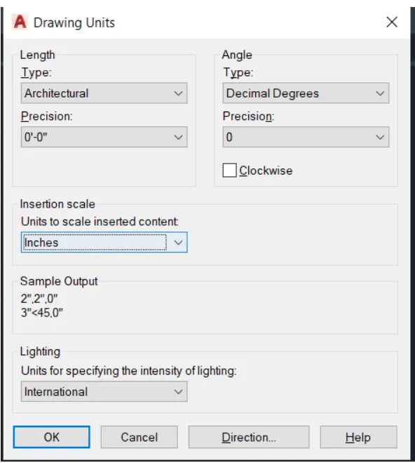
- In the Drawing Units dialog box, select Architectural in Type: 0-0.0" in Precision; and Inches in Insertion scale.
- Click on OK
- Select 3D Modelling from the Workspace Switching drop down list.
- Set the limits by entering LIMITS in the Command tab. The lower-left corner is specified as 0'0.0",0'0.0", and the upper-right corner is specified as 100',100'
- Enter 3DORBIT in the command line.
- Change the UCS view.
- Press Esc.
STEP 2
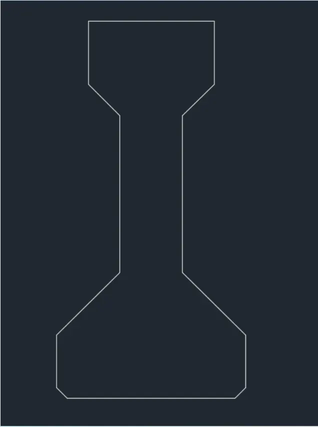
- Select the Top view in the View Cube
- Select the Line tool by entering "LINE command in the command tab
- Specify the first point.
- Draw a horizontal line of length 16"
- Press Esc.
- Select the Offset tool by entering O in the command line.
- Specify offset distance of 6"
- Select the line draw earlier and offset it in the upward direction twice.
- Press Esc.
- Select the Line tool by entering LINE command in the command tab
- Draw a line passing though the middle of the last offsetted line.
- Press Esc.
- Repeat offset, specify distance of 1'6" and offset the last created line in the upward direction.
- Again offset the last line to a distance of 6"
- Press Esc.
- Select the Line tool by entering LINE command in the command tab
- Draw a line of length 1' at the top.
- Press Esc.
- Select the Line tool by entering 'UNE command in the command tab.
- Draw a lines to create the top edges of the section .
- Press Esc.
- ERASE the unwanted lines.
- Enter CHA in the command line to select the Chamfer tool.
- Specify a distance of 1".
- Chamfer the bottom two corners of the I section created.
- Press Esc.
STEP 3
- Enter DST command in the command tab to open the Dimension Style Manager dialog box.
- Click on the Modify tab.
- Under the Lines option change the colour of the dimension and extension lines.
- Under the Symbols and Arrows option change the Arrow size to 2".
- Under the Text option change the Text height to 2".
- Click OK. Then click on Set Current and Close the dialog box.
- Go to Annotate, select DIMLINEAR tool.
- Select the first point and second point of the object to be measured, then drag the dimension line to the desired location. Repeat for all the objects to be measured.
- Press Esc
STEP 4
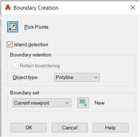
- Enter BOUNDARY command in the command tab.
- Click on Pick points icon in the Boundary Creation Dialog box.
- Click inside the I Section created and press ENTER.
- Press Esc.
- Enter EXT in the command line to select the Extrude tool.
- Select the boundary of the I section.
- Press Enter.
- Extrude it to a height of 10'.
- From the Visual Style Controls drop down list, select the Shaded option.
- Enter 3DORBIT command in the command line and rotate the object.
RESULT:-
Q-4:-
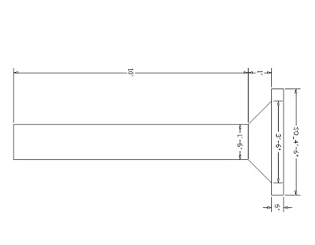
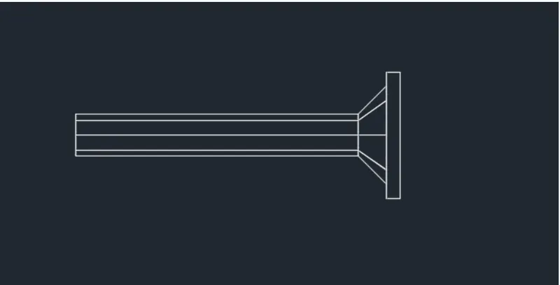
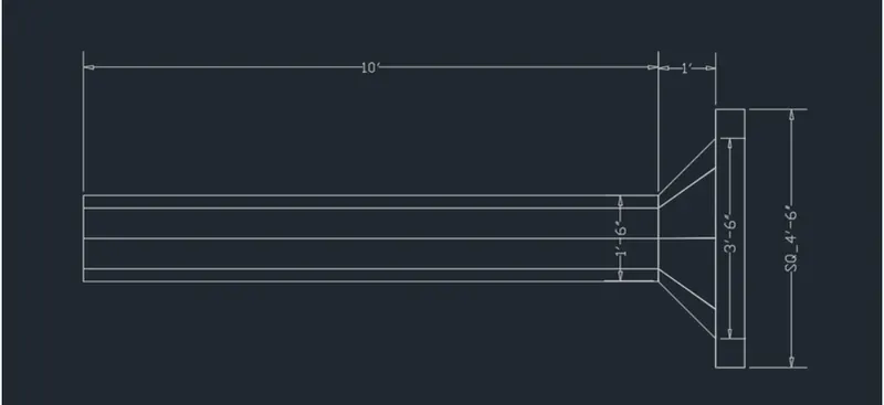
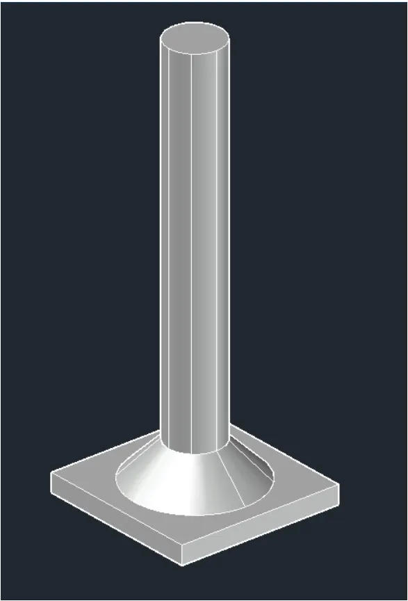
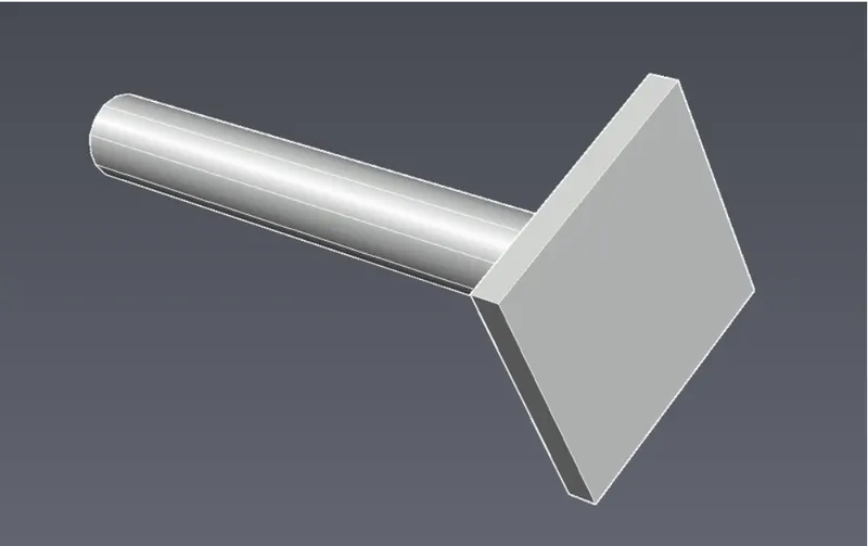
Create a 3d Model of a drop column with panel as shown in section and isometric view.
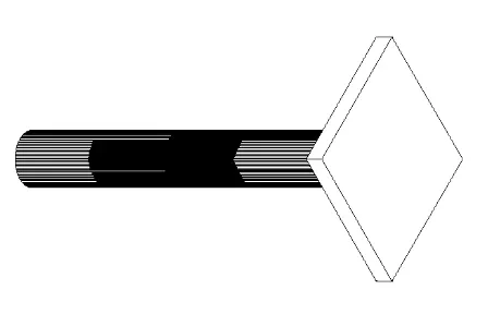
Aim:
To create the 3D Model of a drop column with panel in section and isometric view as shown in the figure above in AutoCAD.
Introduction:
The 3D Model of a drop column with panel as shown in section and isometric view is created in AutoCAD in 3D Modelling workspace using primarily the line tool. The procedure of drawing is explained in detail with diagrams of each step and the final result is given.
Procedure:
STEP 1
- Go to START MENU, select AutoCAD 2022.
- In the Command line type in: STARTUP [ENTER]
- Enter new value of startup: 1
- Go to Application Menu and select New
- Select Imperial, click OK.
- Enter UNITS command in the command tab.
- In the Drawing Units dialog box, select Architectural In Type: 0-0.0" In Precision; and 'Inches in Insertion scale.
- Click on OK.
- Select 3D Modelling from the Workspace Switching drop down list.
- Direction
- Set the limits by entering LIMITS in the Command tab. The lower-left corner is specified as 0'0.0",00,0" and the
- upper-right corner is specified as 100',100'
- Enter 3DORBIT in the command line.
- Change the UCS view.
- Press Esc.
STEP 2
- Select the Rectangle tool by entering 'REC' command in the command tab. Specify the first point.
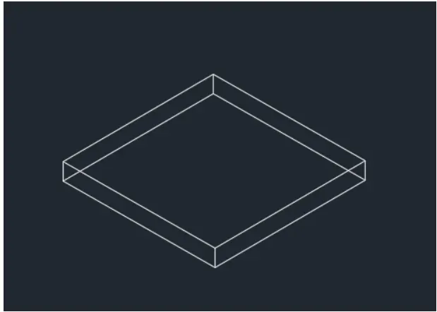
- Specify dimension as @4'6",4'6".
- Select the Extrude tool from the Ribbon and extrude the rectangle to a height of 6"
- Select the Circle tool by entering 'CIRCLE' command in the command tab.
- Specify the centre of the circle.
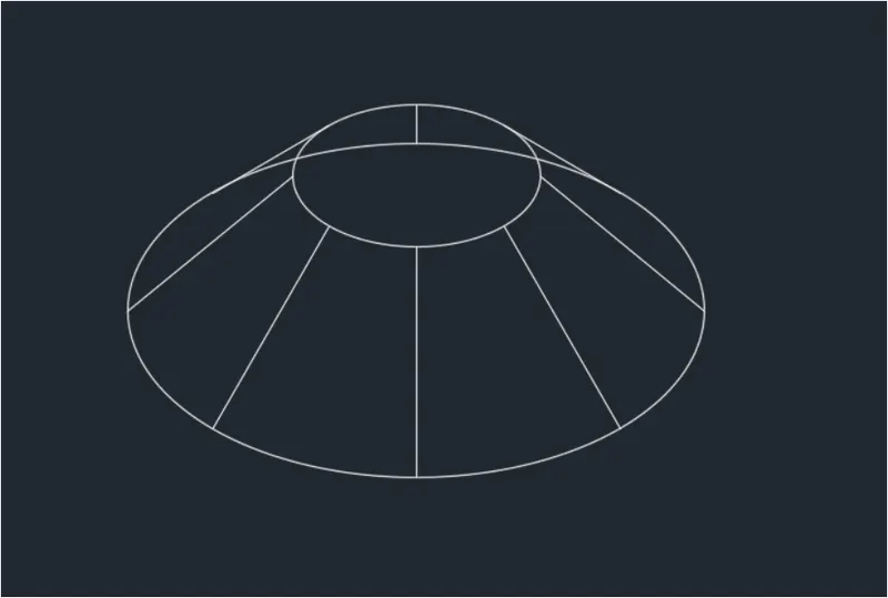
- Select Diameter option. Specify diameter as 3'6".
- Select the line tool and draw a line of height 1' from the centre of the circle.
- Press Esc.
- Select the Circle tool by entering 'CIRCLE' command in the command tab. Specify the centre of the circle as the top end of the line of height 1'.
- Select Diameter option.
- Specify diameter as 1'6".
- Select the Loft tool from the Ribbon and extrude the smaller circle to the larger circle.
- Erase the line of height 1'.
- Select the Circle tool by entering 'CIRCLE' command in the command tab.
- Specify the centre of the circle.
- Select Diameter option.
- Specify diameter as 1'6".
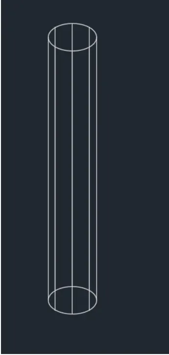
- Select the Extrude tool from the Ribbon and extrude the circle to a height of 10'
STEP 3
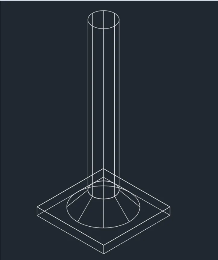
- Select the Move tool by entering M command in the command tab
- Select the truncated cone, specify the centre of the cone as the base point and move it to the centre of the cuboid
- Repeat the same process for the cylindrical object.
STEP 4
- Enter DST command in the command tab to open the Dimension Style Manager dialog box
- Click on the Modify tab.
- Under the Lines option change the colour of the dimension and extension lines.
- Under the Symbols and Arrows option change the Arrow size to 2". Under the Text option change the Text height to 2".
- Click OK. Then click on Set Current and Close the dialog box.
- Go to Annotate, select DIMLINEAR tool.
- Select the first point and second point of the object to be measured, then drag the dimension line to the desired location. Repeat for all the objects to be measured.
- From the Visual Style Controls drop down list, select the Shaded with edges option.
- Enter 3DORBIT command in the command line and rotate the object.
- Save the drawing.
RESULT:
Q-5:-
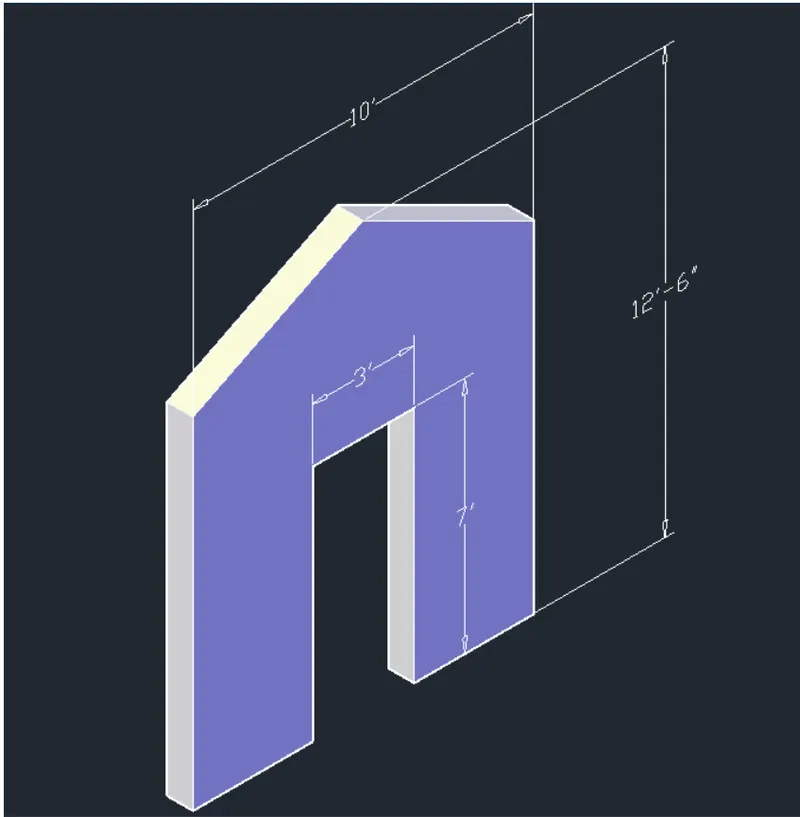
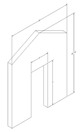
Create the 3d model of a wall as shown in Figure. Consider wall thickness as 9”.
Aim:
To create the 3D Model of a wall as shown in the figure above in AutoCAD.
Introduction:
The 3D Model of the wall is created in AutoCAD in 3D Modelling workspace using primarily the line tool. The procedure of drawing is explained in detail with diagrams of each step and the final result is given.
Procedure:
STEP 1
- Go to START MENU, select AutoCAD 2022
- in the Command line type in: STARTUP (ENTER]
- Enter new value of startup: 1
- Go to Application Menu and select New
- Sect Imperial click OK.
- Enter UNITS command in the command tab.
- in the Drawing Units dialog box, select Architectural in Type; 0-0.0" In Precision; and Inches in Insertion
- Click on OK.
- Select 3D Modelling from the Workspace Switching drop down list.
- Set the limits by entering LIMITS in the Command tab. The lower-left corner is specified as 0'0.0.0'0.0" and the
- upper-right corner is specified as 100',100'
- Enter 3DORBIT in the command line.
- Change the UCS view.
- Press Esc.
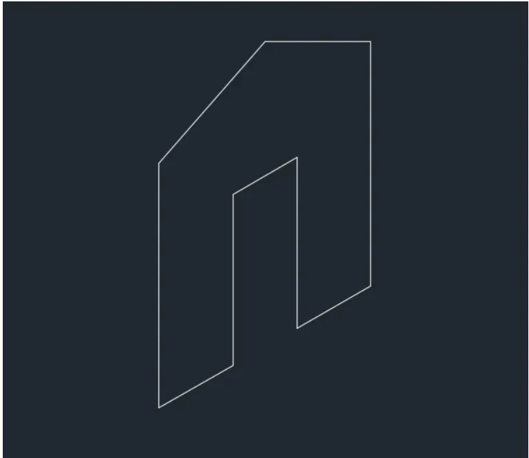
STEP 2
- Select the Line tool by entering 'LINE' command in the command tab
- Select the first point.
- Specify the coordinate of next point as @3'6",0,0 in the command line. Specify the coordinate of next point as @0,0,7' in the command line.
- Specify the coordinate of next point as @3',0,0 in the command line.
- Specify the coordinate of next point as @0,0,-7' in the command line.
- Specify the coordinate of next point as @3'6",0,0 in the command line.
- Specify the coordinate of next point as @0,0,10' in the command line.
- Specify the coordinate of next point as @-10',0,0 in the command line.
- Specify the coordinate of next point as @0,0,-10' in the command line.
- Press Esc.
- Select the Line tool by entering 'LINE command in the command tab
- Draw line of height 2'6" from the middle of the top line.
- Press Esc
- Select the Line tool by entering LINE command in the command tab,
- Daw lines connecting the middle topmost point to both the top left and right conners of the wall.
- Press Esc.
- Select and ERASE unwanted line.
STEP 3
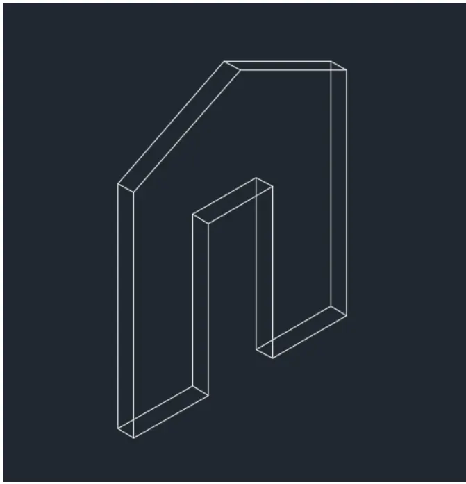
- Enter REGION in the command line.
- Select the entire object created in step 2 and press Enter.
- Select the Extrude tool from the Ribbon.
- Select the object.
- Go to Mode>Direction.
- Specify start point of direction.
- Drag the cursor in the Y direction and specify a distance of 9" (thickness of the wall).
STEP 4
- Enter DST command in the command tab to open the Dimension Style Manager dialog box
- Click on the Modify tab.
- Under the Lines option change the colour of the dimension and extension lines.
- Under the Symbols and Arrows option change the Arrow size to 2".
- Under the Text option change the Text height to 2".
- Click OK. Then click on Set Current and Close the dialog box.
- Go to Annotate, select DIMLINEAR tool
- Select the first point and second point of the object to be measured, then drag the dimension line to the desired location Repeat for all the objects to be measured.
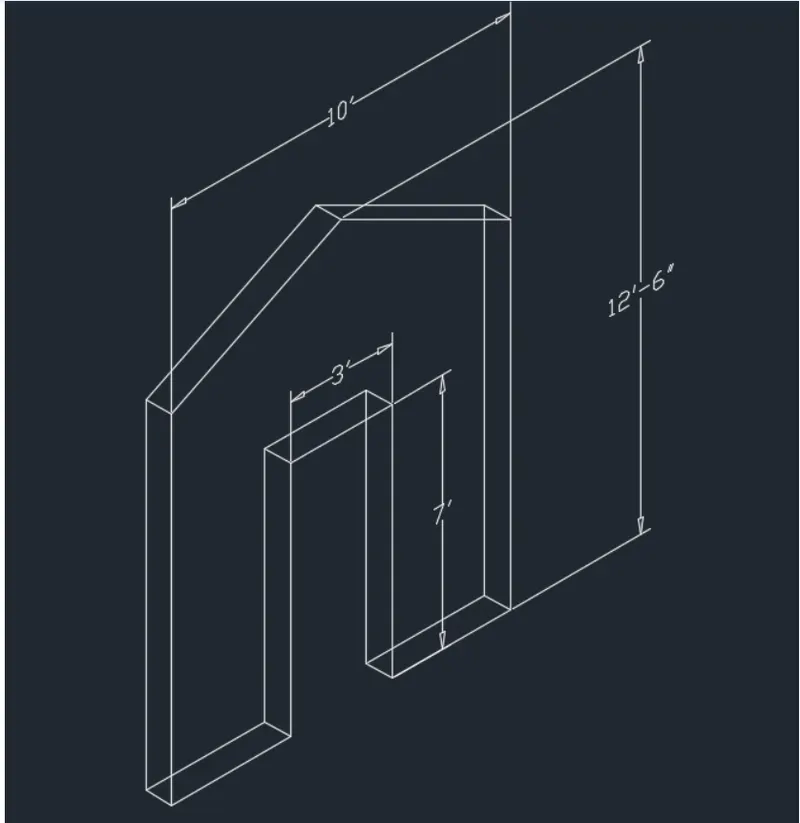
- From the Visual Style Controls drop down list, select the Conceptual option.
- Save the drawing.
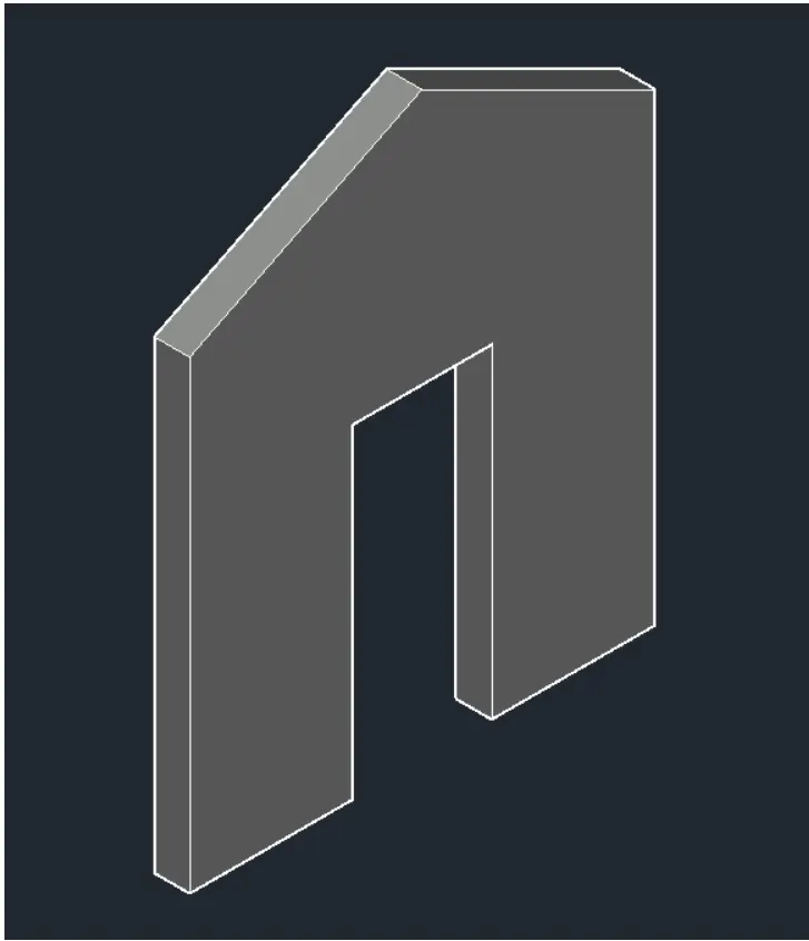
RESULT: