Creating various 3D Models like Furniture, Footing, Girder, Column drop with panel and Gable Wall in AutoCad
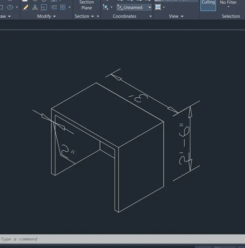
1.Aim: To create the 3d model of furniture unit in the Auto cad engineering system.
- Auto Cad 3d modeling is developed to plot the modules in 3 dimensional or as to develop the solind model of a unit.
- In Auto cad length ,width and height is also plotted in the same plane. In the auto acd 2d Only one plane formed with X and y axis is only used while in the Auto cad 3d model Z axis is also used to plot the height of the model with repect to the X and Y axis.
- In the Auto cad 3d model all the views of the model can be visible simultaneously using the view cube option.
Procedure:
- Click on new File and create the new template for plotting the drawing
- Now enter units (un) command and select the engineering system in the units and also set the precision of the units and insertion scale to inches and click on ok.
- Now click on the settings and change the model space from the drafting and annotation to the 3d modeling.The 3d modeling ribbon bar with various 3d tool bars is uodated in the ribbon.
- Now click on the view cube to change the UCS icon in to the various views as we required.
- Now click on the view cube and set the ucs icon in to the desired plane and the model is plotted on the selected plane of the axis.
- The given model is a furniture unit which is of box shape and it can be plotted by using the rectangle or poly line command.Enter rec in the command bar plot the rectangle the with dimensions of 3'x2'6".
- Then the bottom side trimmed using the trim command and the thickness of the unit 2" is developed using the offset command.
- Now the unit created as a region for the developing the solid unit, Enter the region in the command bar and select the unit and press enter then the whole unit is developed as a region.
- The unit is extrude with an desired thickness for the making as a solid unit.The extrude command will be worked only for the units which are created with the regions only.
- Now eneter the extrude command in the command bar and select the region of the model and enter the dis tance to which the model is to be extruded and press enter then the model is extruded to the required thickness and formed as a solid model.
- Now using view cube or 3d orbit command the modelturned to back to create the backside face, otherwise it will be displayed as a hallow unit when we shade the unit.
- Enter 3d orbit inthe command bar and change the model to the backside and create the face using the rectangle command to a size of 3'x2'6".
- Now eneter 3d face command inthe command bar and create the face by selecting the boundry points of the unit.
- Now enter the dimlinear command and plot the dimensions of the model.The ucs icon is changed to the respective plane where the dimensions are being plotted.
- Now we can get the solid model by changing the mode of the model space from 2d wire frame to the shaded option.
- The result of the 3d model of the furniture unit is obtained as shown below.
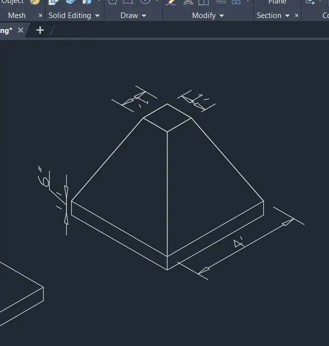
2.Aim: To create the 3d model of Isolated footing unit in the Auto cad engineering system.
- Auto Cad 3d modeling is developed to plot the modules in 3 dimensional or as to develop the solind model of a unit.
- In Auto cad length ,width and height is also plotted in the same plane. In the auto acd 2d Only one plane formed with X and y axis is only used while in the Auto cad 3d model Z axis is also used to plot the height of the model with repect to the X and Y axis.
- In the Auto cad 3d model all the views of the model can be visible simultaneously using the view cube option.
Procedure:
- Click on new File and create the new template for plotting the drawing
- Now enter units (un) command and select the engineering system in the units and also set the precision of the units and insertion scale to inches and click on ok.
- Now click on the settings and change the model space from the drafting and annotation to the 3d modeling.The 3d modeling ribbon bar with various 3d tool bars is updated in the ribbon.
- Now click on the view cube to change the UCS icon in to the various views as we required.
- Now click on the view cube and set the ucs icon in to the desired plane and the model is plotted on the selected plane of the axis.
- The given model is a isolated footing which is of trapezoidal shape and it can be plotted by using the rectangle or poly line command.Enter rec in the command bar plot the rectangle the with dimensions of 4'x4'.
- Now enter off set command and create the another retangle with the offset distance of 6" and the corners are joined with the straight lines on all the four corners.
- Now the unit created as a region for the developing the solid unit, Enter the region in the command bar and select the top face of the unit and press enter then the top face of the unit is developed as a region.
- The unit is extrude with an desired thickness for the making as a solid unit.The extrude command will be worked only for the units which are created with the regions only.
- Now eneter the extrude command in the command bar and select the region of the model and enter the dis tance to which the model is extruded. Here the footing is isolate model and it is created by using the taper angle option in the extrude command i.e by enter the taper angle of between 90 degrees to -90 degrees and press enter and then enter height of the footing as 3' and press enter then the model is extruded to the required thickness and formed as a solid model.
- Enter 3d orbit inthe command bar and change the model to the backside and create the faces of the bottom rectangle on all the four sides and also in the bottom.
- Now eneter 3d face command inthe command bar and create the face by selecting the boundry points of the unit.
- Now enter the dimlinear command and plot the dimensions of the model.The ucs icon is changed to the respective plane where the dimensions are being plotted.
- Now we can get the solid model by changing the mode of the model space from 2d wire frame to the shaded option.
- The result of the 3d model of the isolated footing model is obtained as shown below.
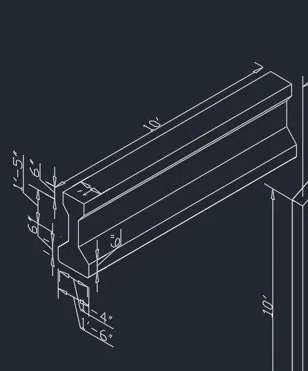
3.Aim: To create the 3d model of AASTHO type girder unit in the Auto cad engineering system.
- Auto Cad 3d modeling is developed to plot the modules in 3 dimensional or as to develop the solind model of a unit.
- In Auto cad length ,width and height is also plotted in the same plane. In the auto acd 2d Only one plane formed with X and y axis is only used while in the Auto cad 3d model Z axis is also used to plot the height of the model with repect to the X and Y axis.
- In the Auto cad 3d model all the views of the model can be visible simultaneously using the view cube option.
Procedure:
- Click on new File and create the new template for plotting the drawing
- Now enter units (un) command and select the engineering system in the units and also set the precision of the units and insertion scale to inches and click on ok.
- Now click on the settings and change the model space from the drafting and annotation to the 3d modeling.The 3d modeling ribbon bar with various 3d tool bars is updated in the ribbon.
- Now click on the view cube to change the UCS icon in to the various views as we required.
- Now click on the view cube and set the ucs icon in to the desired plane and the model is plotted on the selected plane of the axis.
- The given model is a AASTHO type girder which is of rail section shape and it can be plotted by using the rectangle or poly line command.Enter rec in the command bar plot the rectangle the with dimensions of 1'x1'
- Again enter the rec command and develop another rectangle at a distance of 3' to a size of 1'4"x6" from the primarily formed rectangle.
- Now enter poly line command and develop the slope of the bootm face at an inclination of 45 degrees to a length of 1" at the bottom line of the rectangle.
- Now explode the rectangle of size 1'4"x6" and offset the bottom line with an offset command to an offset distance of 1" and stretch the line to a distance of 1" on both the ends.
- Enter the poly line command and draw the vertical lines (which will be the web of the girder)from the vertical faces of the topline.
- Now enter the trim command and trim the unwanted lines and edges of the unit and so the model of the girder is formed.
- Now the unit created as a region for the developing the solid unit, Enter the region in the command bar and select the top face of the unit and press enter then the top face of the unit is developed as a region.
- The unit is extrude with an desired thickness for the making as a solid unit.The extrude command will be worked only for the units which are created with the regions only.
- Now eneter the extrude command in the command bar and select the region of the model and enter the dis tance to which the model is extruded and then enter height of the footing as 10' and press enter then the model is extruded to the required thickness and formed as a solid model.
- Now enter the dimlinear command and plot the dimensions of the model.The ucs icon is changed to the respective plane where the dimensions are being plotted.
- Now we can get the solid model by changing the mode of the model space from 2d wire frame to the shaded option.
- The result of the 3d model of the AASTHO girder unit is obtained as shown below.
4.Aim: To create the 3d model of Drop column unit in the Auto cad engineering system.
- Auto Cad 3d modeling is developed to plot the modules in 3 dimensional or as to develop the solind model of a unit.
- In Auto cad length ,width and height is also plotted in the same plane. In the auto acd 2d Only one plane formed with X and y axis is only used while in the Auto cad 3d model Z axis is also used to plot the height of the model with repect to the X and Y axis.
- In the Auto cad 3d model all the views of the model can be visible simultaneously using the view cube option.
Procedure:
- Click on new File and create the new template for plotting the drawing
- Now enter units (un) command and select the engineering system in the units and also set the precision of the units and insertion scale to inches and click on ok.
- Now click on the settings and change the model space from the drafting and annotation to the 3d modeling.The 3d modeling ribbon bar with various 3d tool bars is updated in the ribbon.
- Now click on the view cube to change the UCS icon in to the various views as we required.
- Now click on the view cube and set the ucs icon in to the desired plane and the model is plotted on the selected plane of the axis.
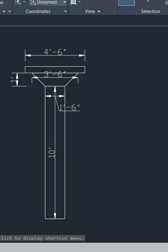
- The given model is a circular drop column and it can be plotted by using the circle command.Enter c in the command bar plot the circle with diameter of 1'6".
- Now the unit created as a region for the developing the solid unit, Enter the region in the command bar and select the top face of the unit and press enter then the top face of the unit is developed as a region.
- The unit is extrude with an desired thickness for the making as a solid unit.The extrude command will be worked only for the units which are created with the regions only.
- Now eneter the extrude command in the command bar and select the region of the model and enter the dis tance to which the model is extruded and then enter height of the footing as 10' and press enter then the model is extruded to the required thickness and formed as a solid model.
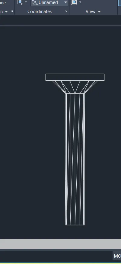
- The drop panel is created with the circle command extruded with the taper angle.Enter c in the command bar and circle is created with the diameter of 1'6" and it is extruded with the taper angle of -45degrres to a height of 1'.
- The panel is created over with the rectangle command extruded with an and it is placed with respect to the centre of the circle.
- The section of the column is same as that of size and it is formed on the 2d plane with rectangle command and the section is developed by cuting the section at the centre of the column.
- Now enter the dimlinear command and plot the dimensions of the model.The ucs icon is changed to the respective plane where the dimensions are being plotted.
- Now we can get the solid model by changing the mode of the model space from 2d wire frame to the shaded option.
- The result of the 3d model and the sectional view of the drop panel column unit is obtained as shown below.
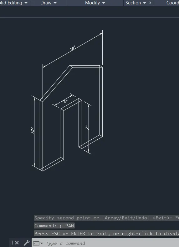
5.Aim: To create the 3d model of a wall with a gabled roof unit in the Auto cad engineering system.
- Auto Cad 3d modeling is developed to plot the modules in 3 dimensional or as to develop the solind model of a unit.
- In Auto cad length ,width and height is also plotted in the same plane. In the auto acd 2d Only one plane formed with X and y axis is only used while in the Auto cad 3d model Z axis is also used to plot the height of the model with repect to the X and Y axis.
- In the Auto cad 3d model all the views of the model can be visible simultaneously using the view cube option.
Procedure:
- Click on new File and create the new template for plotting the drawing
- Now enter units (un) command and select the engineering system in the units and also set the precision of the units and insertion scale to inches and click on ok.
- Now click on the settings and change the model space from the drafting and annotation to the 3d modeling.The 3d modeling ribbon bar with various 3d tool bars is uodated in the ribbon.
- Now click on the view cube to change the UCS icon in to the various views as we required.
- Now click on the view cube and set the ucs icon in to the desired plane and the model is plotted on the selected plane of the axis.
- The given model is a wall unit which is of rectangular shape and it can be plotted by using the rectangle or poly line command.Enter rec in the command bar plot the rectangle the with dimensions of 10'x10'.
- Now enter rec command and plot the rectangle in the 7'x3' in the center of the primarily formed rectangle.
- Now using the trim command the bottom portion of the rectangle is trimmed.
- Now enter the poly line command and the gable shape of the wall is formed with the size of 10'x2'6" with inclination to the vertex at the centre of the wall.
- Now the unit created as a region for the developing the solid unit, Enter the region in the command bar and select the unit and press enter then the whole unit is developed as a region.
- The unit is extrude with an desired thickness for the making as a solid unit.The extrude command will be worked only for the units which are created with the regions only.
- Now eneter the extrude command in the command bar and select the region of the model and enter the dis tance to which the model is to be extruded and press enter then the model is extruded to the required thickness of 6" and formed as a solid model.
- Now enter the dimlinear command and plot the dimensions of the model.The ucs icon is changed to the respective plane where the dimensions are being plotted.
- Now we can get the solid model by changing the mode of the model space from 2d wire frame to the shaded option.
- The result of the 3d model of the wall with a gabeled roof unit is obtained as shown below.