Creating various 3D Models like Furniture, Footing, Girder, Column drop with panel and Gable Wall in AutoCad
1.Aim & Introduction
Aim
This challenge aims to let the student utilize the tools in Autocad to create a 3D sketch. It aims to help the student familiarize with thedifferent 3D commands present in the AutoCAD software. This challenge aims to correlate the 2D drawing into 3D sketches
Introduction
The AutoCAD software provides different tools. used in this challenge is as described below:
Line- creates line object
Polyline- creates rectangle line object
Rectangle- creates rectangles object
Circle- create circle object
Trim-Cut unwanted lines or shapes with the provided cutting edges
Extended- Extend lines to opposite corners
Move- Move objects to particular locations
Copy- Copy obejects to particular locations
Rotate- Rotate selected objects to a particular angle with respect to base point
Array- Copy an object in a set path linearly or polarly
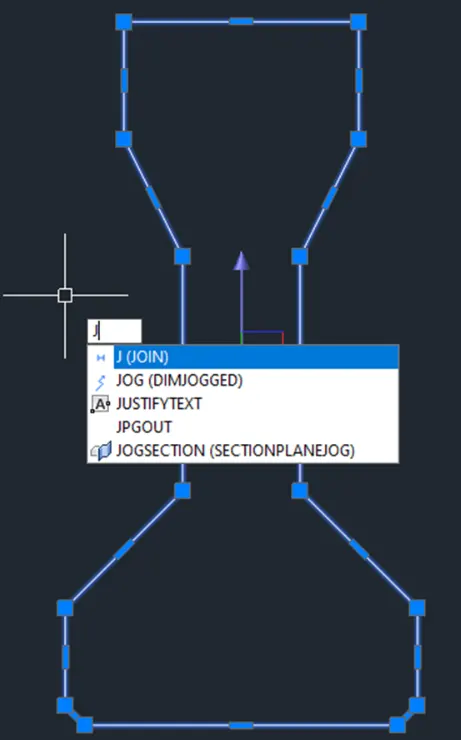
Join- Joins separated line objects to a particular angle with respect to base point
Dimlinear(DLI)- provides vertical or horizontal linear/ straight dimensions
Dimligned(DAL)- Provides dimensions with respect to the angle of the object
Dimangular(DAN)- Provides angular dimensions between two line objects.
Quicklinedimension(QDIM)-provides quick dimension of a geometry
Leader- creates an arrow head line
Layer- Provides identification of line or object groups by their properties
Units- Open "Drawings Units" window to specify to modify the dimension properties
Hatch- provides hatching pattern in a given object or internal point
3D orbit- allows panning in the 3D view
Extrude- Creates a 3D solid, surfaces, or 2D regions by subtraction
UCS- Manages defined user corodinate systems
Union-Unions two solid or two region objects
2. Sketch and Procedure:
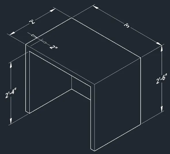
A. Create a 3D Furniture element as shown in the figure. Assume dimensions which are missing
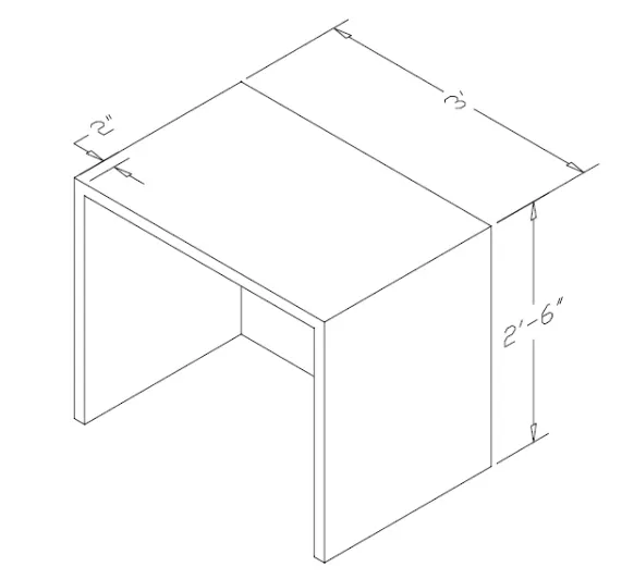
PROCEDURE:
- Create 2D face
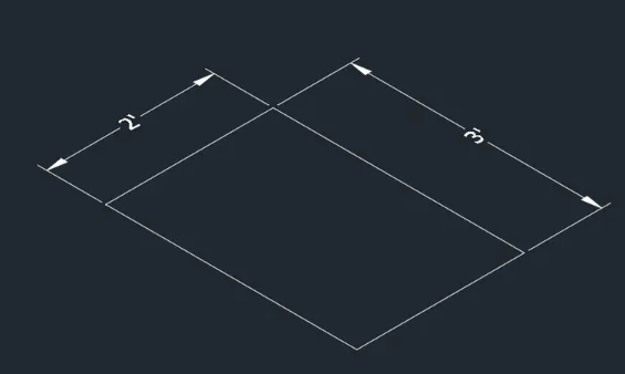
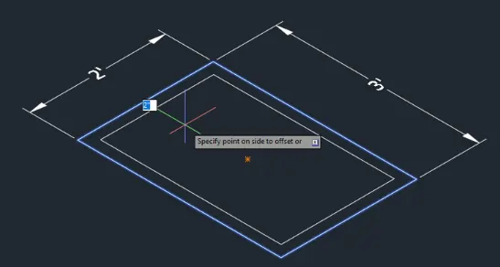
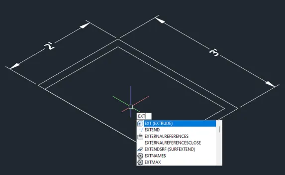
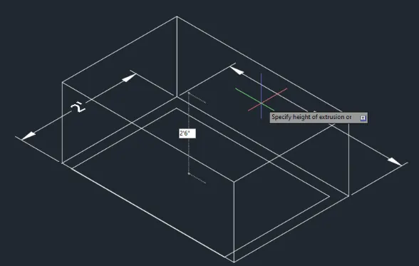
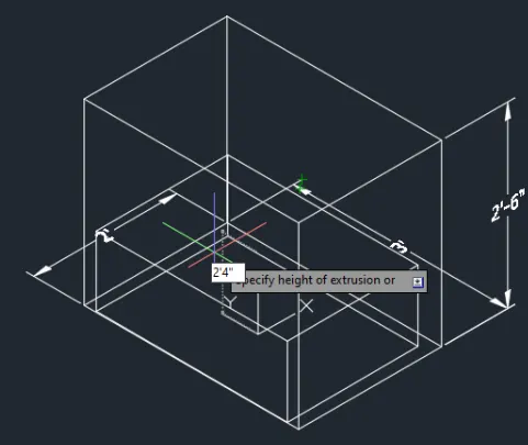
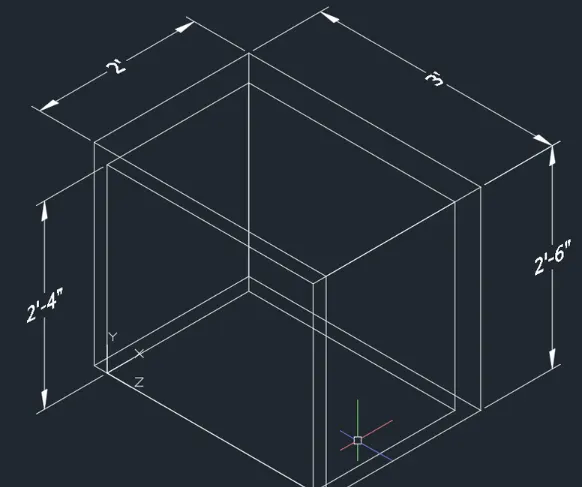
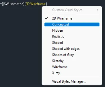
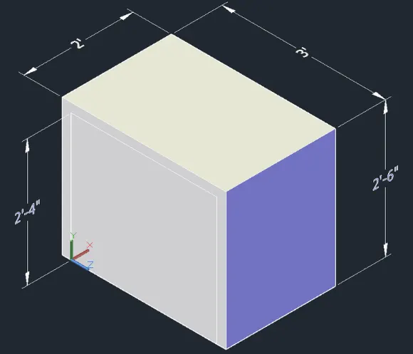
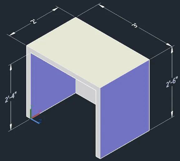
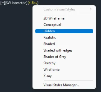
Results:
B. Create the 3D model of an isolated footing as shown in figure
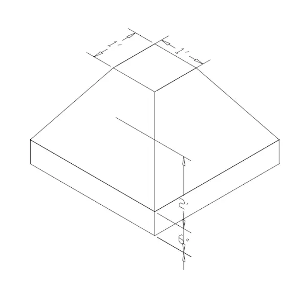
Procedure:
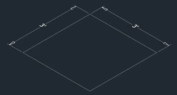
- Extrude
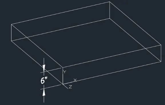
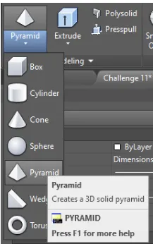
- Use top of solid as base. Top radius is 6"
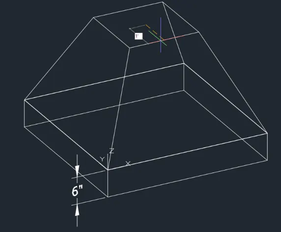
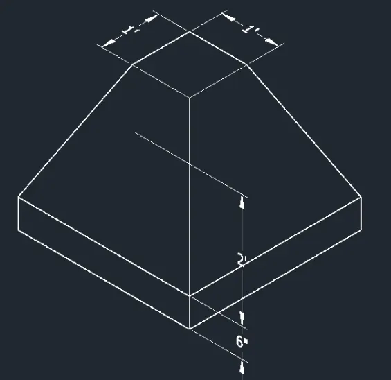
- Use Hidden view for final product
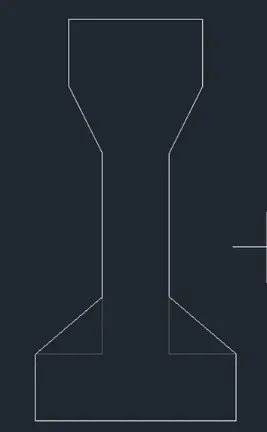
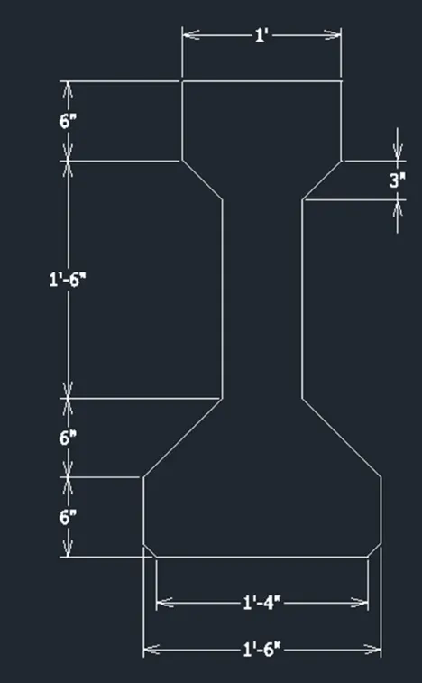
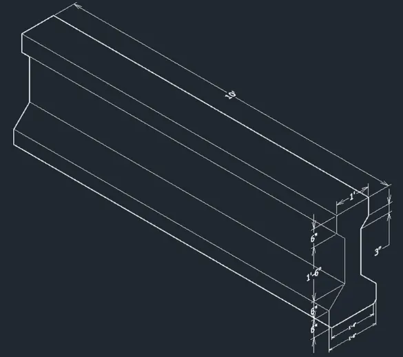
C. Create the 3D view of the AASTHO Girder
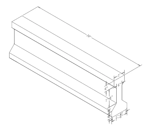
PROCEDURE:
- Create 2D Drawing in front view
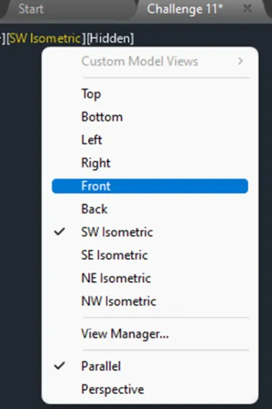
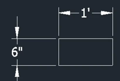
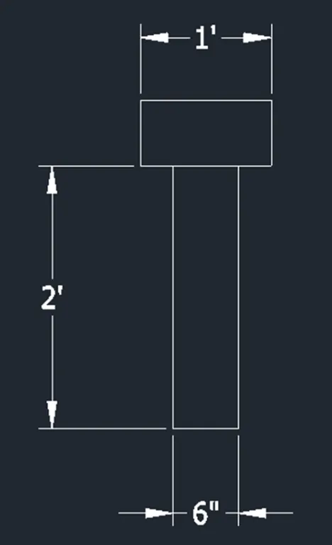
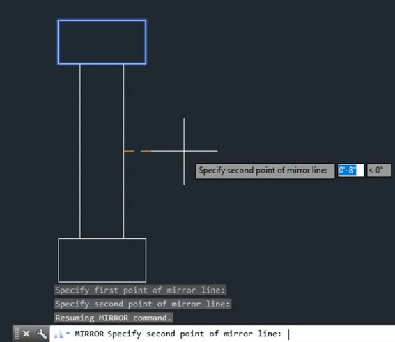
- Stretch to expand
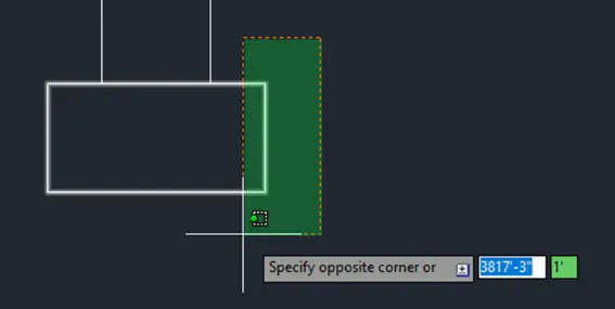
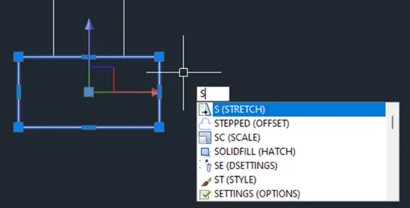
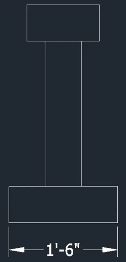
- Trim line
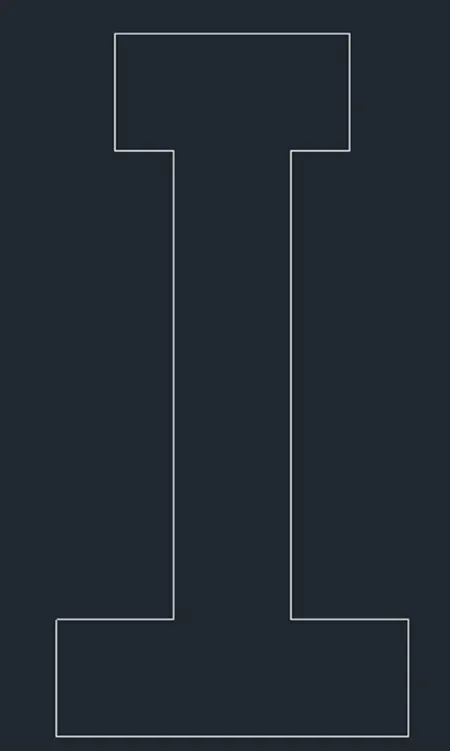
- Strech to achieve correct shape
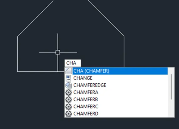
- Chamfer bottom part by 1"
- Go to 3D view
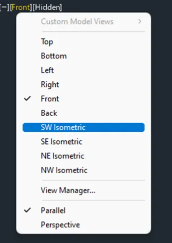
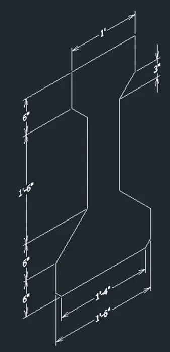
- Extrude by the correct length
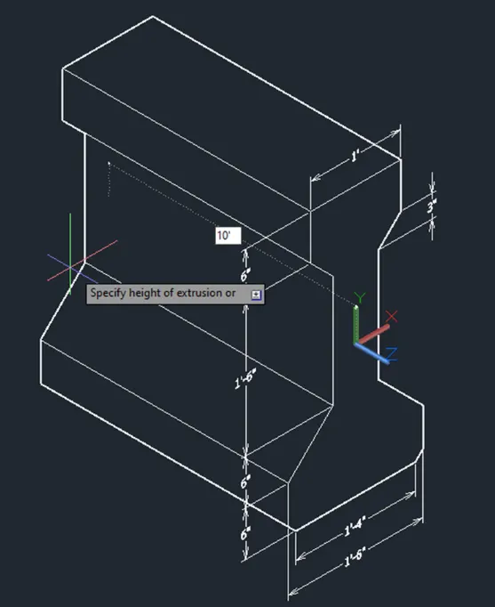
Results:
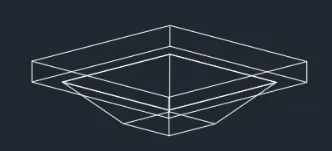
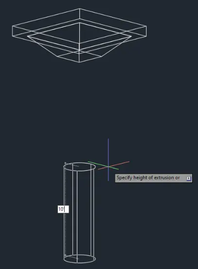
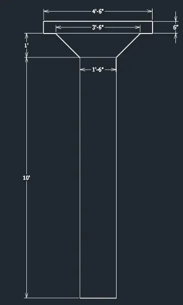
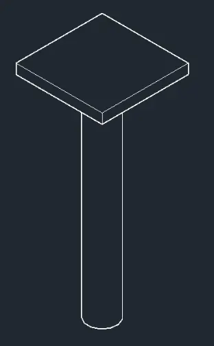
D.Create a 3D model of a drop column with panel as shown in section and isometric view
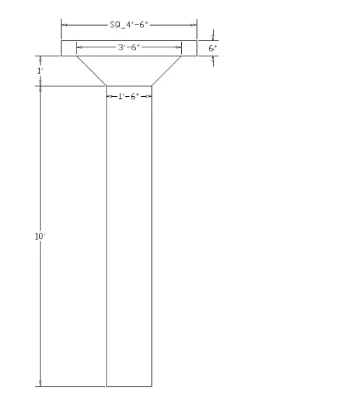
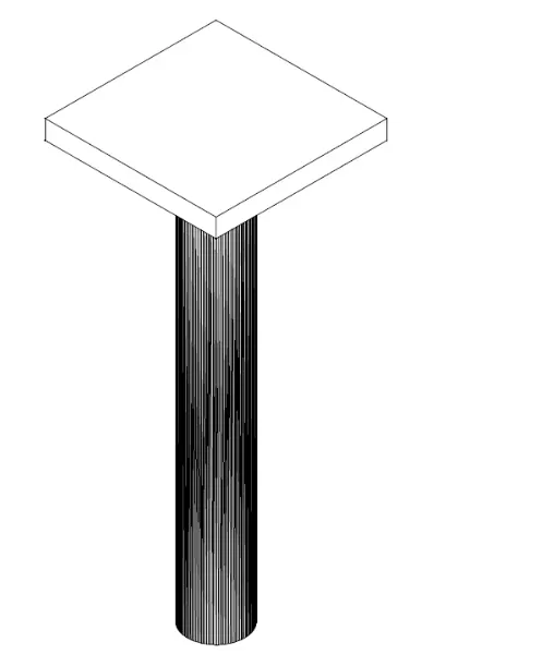
Procedure:
- Create 2D drawing
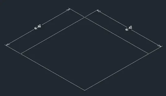
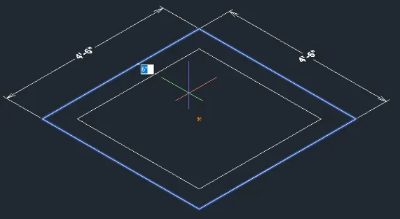
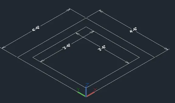
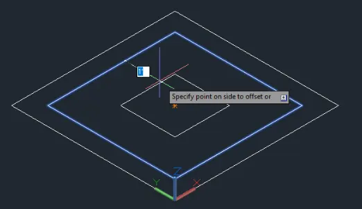
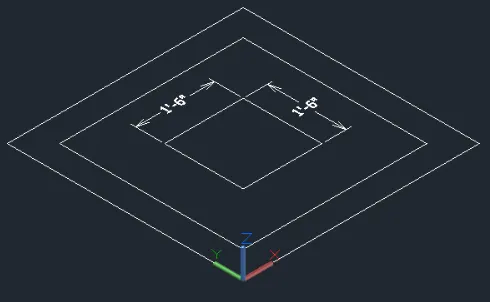
- Change object elevations
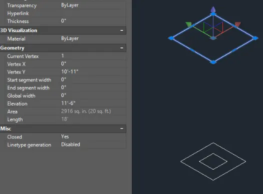
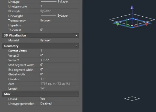
- Change bottom shape to circle
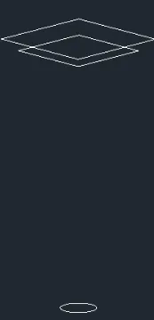
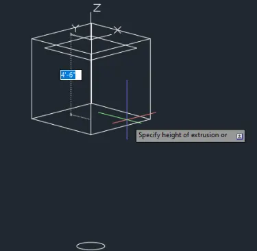
- Extrude the objects and use pyramid command on the trapezoidal part
- Extrude top by 6" to the bottom
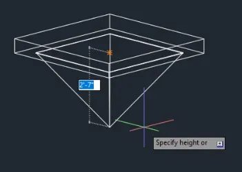
- Top radius is 8" and height is 1'
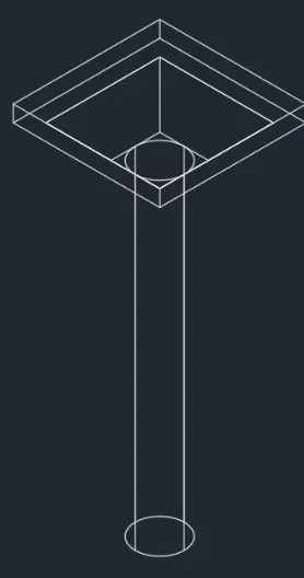
Results:
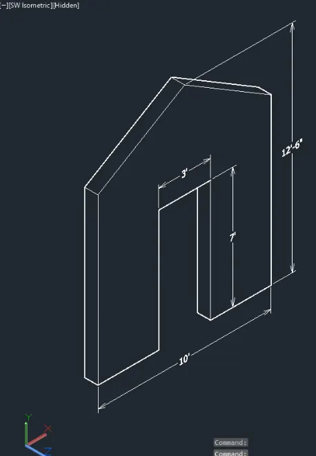
E. Create the 3D model of a wall as shown in figure. Consider wall thickness as 9"
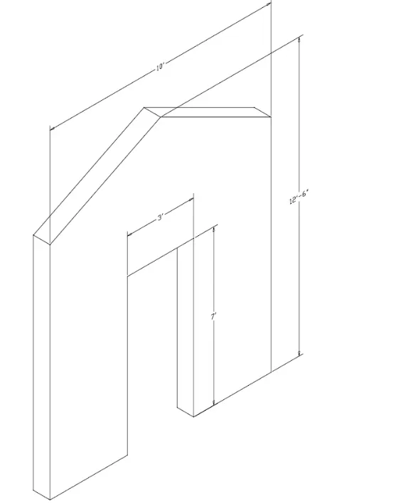
PROCEDURE:
- Create the 2D drawing in front view
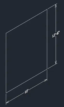
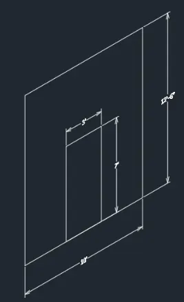
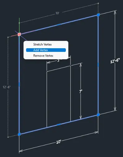
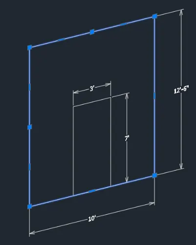
- Strech the lines to make the triangle
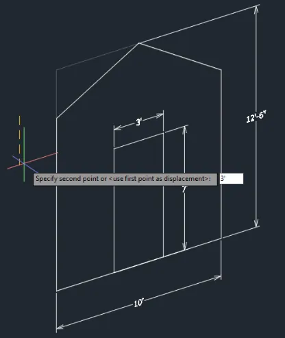
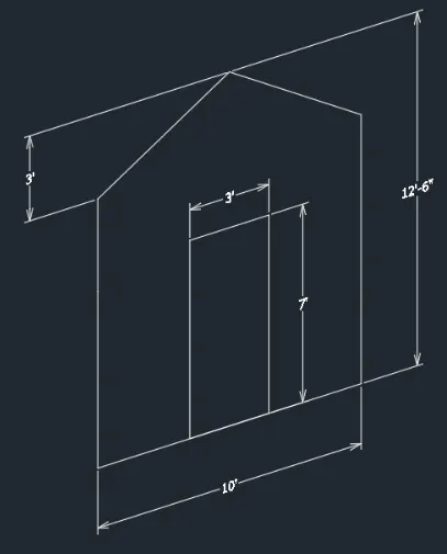
- Extrude the objects
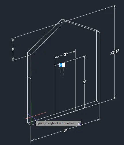
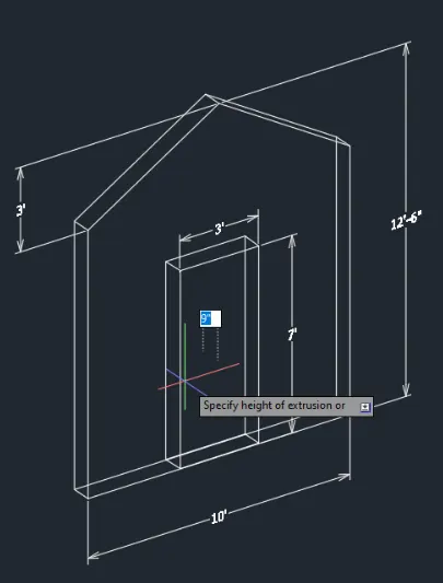
- Subtract the solids
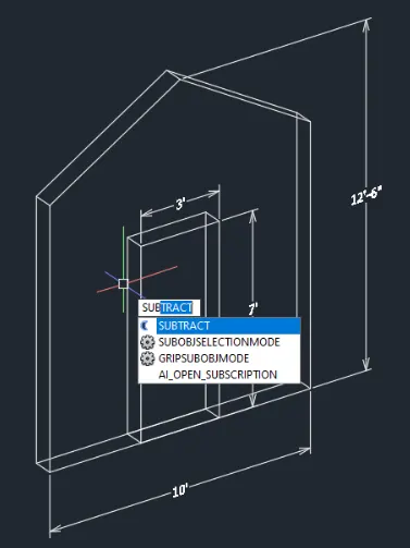
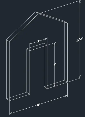
- Use SW Isometric and Hidden view for the final product
Results:
3. Conclusion:
The AutoCAD software allowa 3D sketches where solid objects or 3D surface are present. By using the 3D function of the AutoCAD software, one can illustarte or convert a 2D sketch into 3D illustration. This creates or allows the user to create multiple views including the perspective. By using the viewport command of the AutoCAD software, there full view of a 3D sketch can be achieve.