Creating various 3D Models like Furniture, Footing, Girder, Column drop with panel and Gable Wall in AutoCad
1)
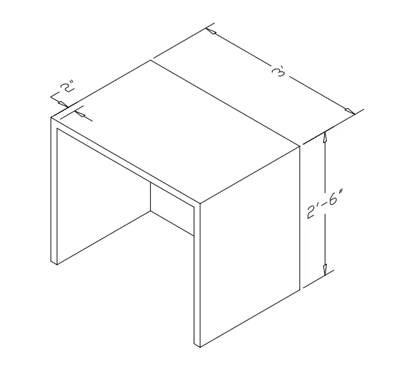
Aim - To create 3D furniture elements as shown in figure .
Introduction - i) In an given figure 3D wireframe model is given as furnitures .
ii) 3D wireframe model can be drawn by using various coordinate sysrtem
a) Rectangular coordinate system
b) Relative coordinate system
c) Spherical coordinate sytem
d) Cyclindrical coordinate system
iii) Following Commands are used -
a) Line
b) Rectangle
c) Extrude
d) 3DMove
e) Copy
f) Dim
g) 3D faces
h) Region
Procedure -
i) Open a New drawing (Cntrl + N) select Imperical units ( Feet and Inches )
ii) Select units to Engineering and select precision as Inches (0'0.0")
iii) Command DS / Drafting settings - Change the Snap spacing and Grid spacing 1' and Change major lines
every grid to 5 .
iv) Change the workspace setting from Drafting and Annotations to 3D Modeling .
Step By Step Procedure -
Step 1)
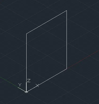
i) Command line
ii) Specify 1st point as 0,0,0
iii) Specify next point as 2',0,0
iv) Specify next point as @0,0,2'6" - ( Relative system )
v) Specify next point as @-2',0,0
vi) Close the line .
Step 2)
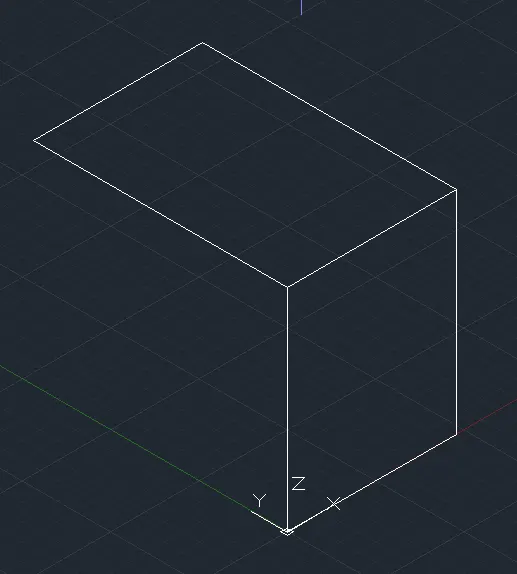
i) Command Offset
ii) Select the line of 2'
iii) Command offset and give distance 3' in positive y direction
iv) And join the remaining lines . ( Upper Surface is created )
Step 3)
i) Command Line
ii) Draw the vertical line @0',0',-2;6" ( left side view is created )
iii) Specify next point as @0 , 3' , 0 ( from origin )
iv) Specify next point as @0,2",0) to draw the thickness of left side view .
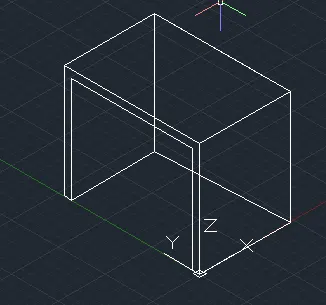
Step 4)
i) Commadn 3D faces
ii) Draw the 3d faces
iii) Select the edges of the object
iv) Press Enter .
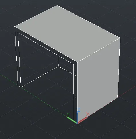
Step 5)
i) Command layers
ii) Add the layers
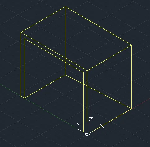
Change the view style to - Hidden
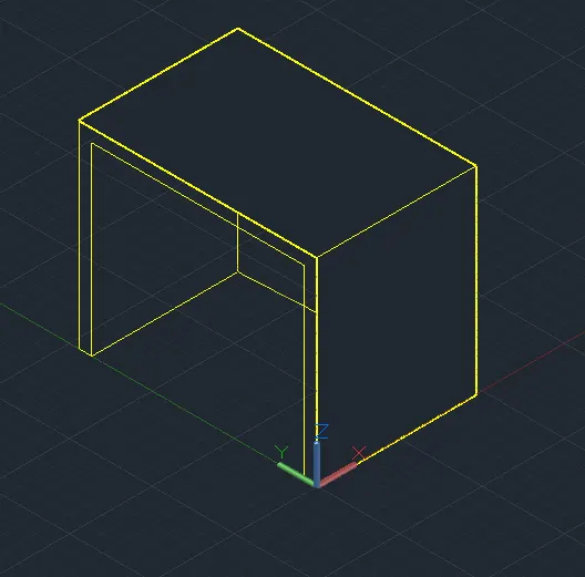
Change the view style to - Shaded
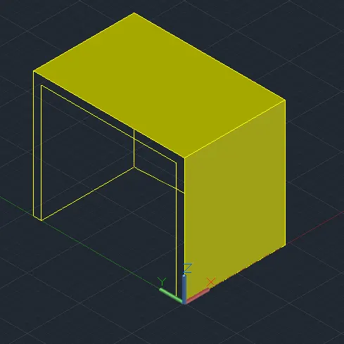
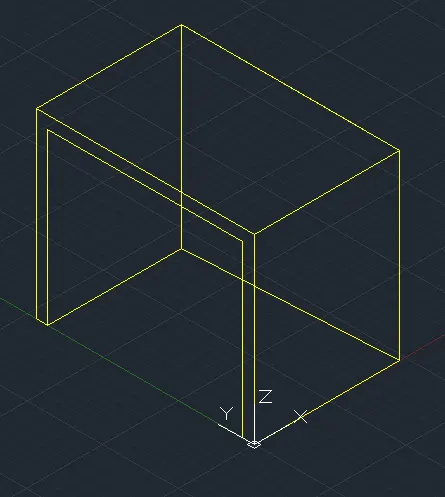
Result - A 3d Furniture element is draw as shown in fig .
i) 2d Wire Frame
ii) Hidden
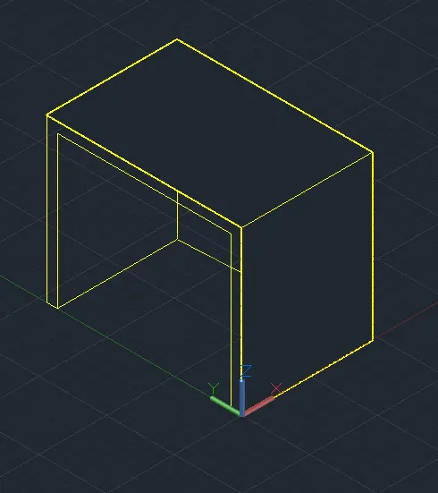
iii) Shaded
2)
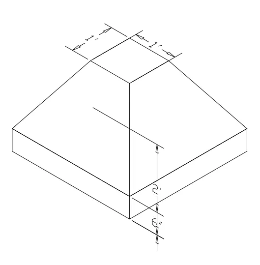
Aim - To create the 3d model of an Isolated footing
Introduction - i) In an given figure 3D model of an Isolated foting is given .
ii) 3D wireframe model can be drawn by using various coordinate sysrtem
a) Rectangular coordinate system
b) Relative coordinate system
c) Spherical coordinate sytem
d) Cyclindrical coordinate system
iii) Isolated Footing is provided for an individual columns
iv) Types of isolated footing are - i) Square footing
ii) Rectangular Footing
iii) Trapezoidal footing
iii) Following Commands are used -
a) Line
b) Rectangle
c) Extrude
d) Move
e) Copy
f) Dim
g) 3d Faces
Procedure -
i) Open a New drawing (Cntrl + N) select Imperical units ( Feet and Inches )
ii) Select units to Engineering and select precision as Inches (0'0.0")
iii) Command DS / Drafting settings - Change the Snap spacing and Grid spacing 1' and Change major lines
every grid to 5 .
iv) Change the workspace setting from Drafting and Annotations to 3D Modeling .
Step by step Procedure
Step 1) Creating bottom surface
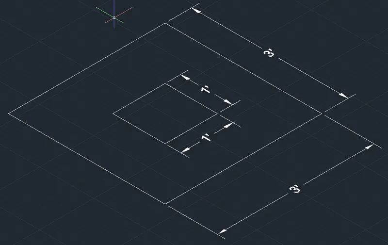
i) Assume the base dimensions as 3' x 3'
ii) Command Rectangle
iii) Specify base points as 0,0,0
iv) Enter length = 3'
v) Enter width = 3'
vi) Again Command Rectangle
vii) Enter the length = 1'
viii) Enter the width - 1'
ix) Commad Dim and measure the dimensions
Step 2)
i) Command move
ii) Select the inner surface
iii) and move the surface at a distance of 2'

Step 3)
i) Command Extrude
ii) Extrude the bottom surface at a distance of 6"
iii) Command line and Join the edges of top surface and bottom surface .
iv) Command 3d orbit
v) Rotate the view and join the backside edges .
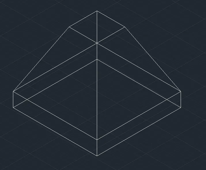
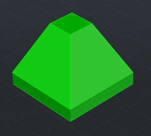
Results - A 3d model of an Isolated footing is created
i) 2d wireframe model
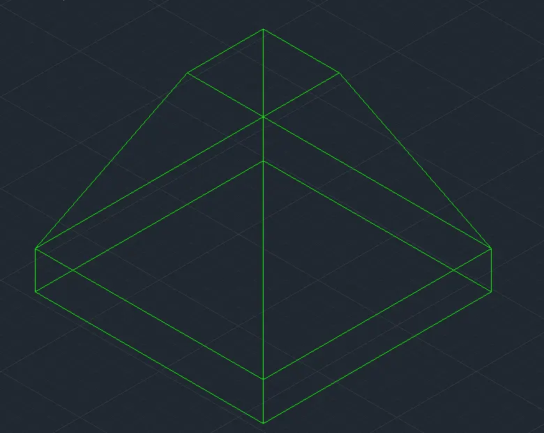
ii) Hidden
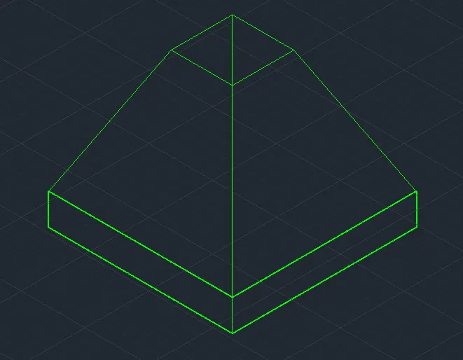
iii) Shaded
3)
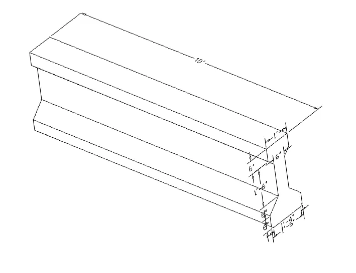
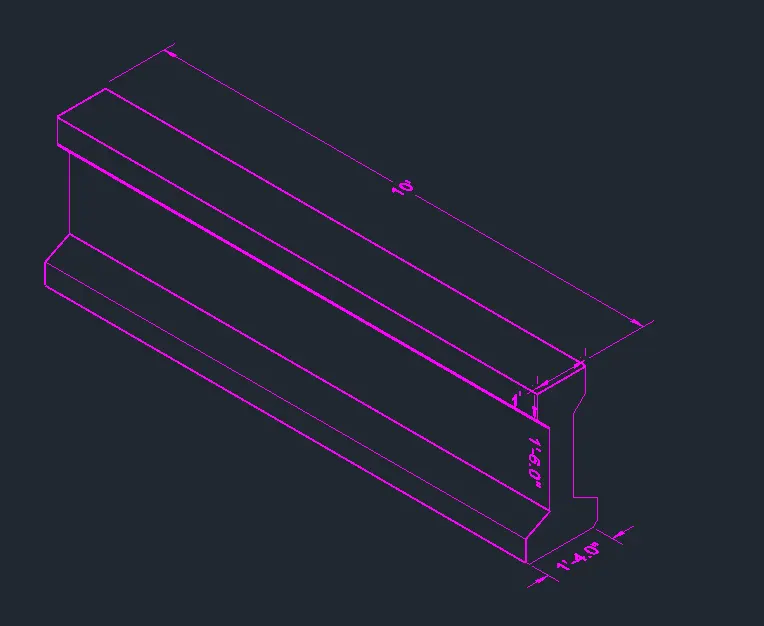
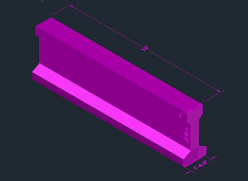
Aim - To create the 3d view of AASTHO type girder
Introduction - i) In an given figure 3D view of AASTHO type girder is given .
ii) 3D wireframe model can be drawn by using various coordinate sysrtem
a) Rectangular coordinate system
b) Relative coordinate system
c) Spherical coordinate sytem
d) Cyclindrical coordinate system
iii) Following Commands are used -
a) Line
b) Sweep
c) Copy
d) Dim
e) 3D faces
Procedure -
i) Open a New drawing (Cntrl + N) select Imperical units ( Feet and Inches )
ii) Select units to Engineering and select precision as Inches (0'0.0")
iii) Command DS / Drafting settings - Change the Snap spacing and Grid spacing 1' and Change major lines
every grid to 5 .
iv) Change the workspace setting from Drafting and Annotations to 3D Modeling .
Step by Step Procedure -
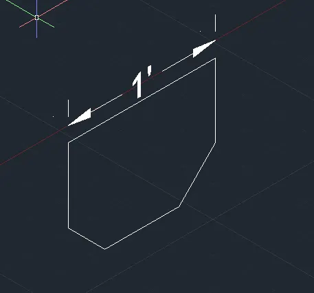
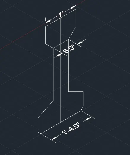
Step 1) Create an I section
i) Command Line
ii) Specify 1st point as 0,0,0
iii) Specify next point @1',0,0 ( Relative coordinate system )
iv) Specify next point @0,0,6"
v) copy this line on both side of 1' line
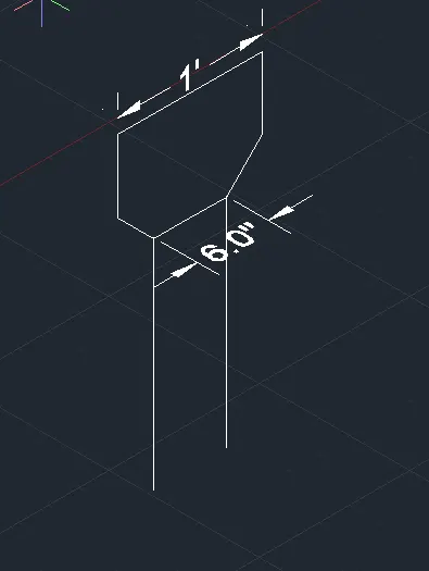
vi) From the midpoint of the 1' line draw the vertical line of 3'
vii) From the vertical line draw the line of 3" on both side such that web portion is created .
viii) then join the edges of web portion and flange portion
ix) Draw the 1'6" vertical line of web portions
Step 2) Bottom portion
i) We have already draw the 3' line from the midpoint of the top flange
ii) Command Line
iii) From the bottom point of the 3' line Specify point @8" ,0 ,0
iv) Command Copy
v) Copy this line to the other side also
vi) Now draw the 6" vertical line from both the end .
vii) And join the bottom of web portion and bottom flange by inclined line .
Step 3)
i) Draw the line of @0,10',0 from the top
ii) Command Sweep
iii) Select the object of I section
iv) Select the path i,e 10' line which we have drawn earlier
v) Press enter .
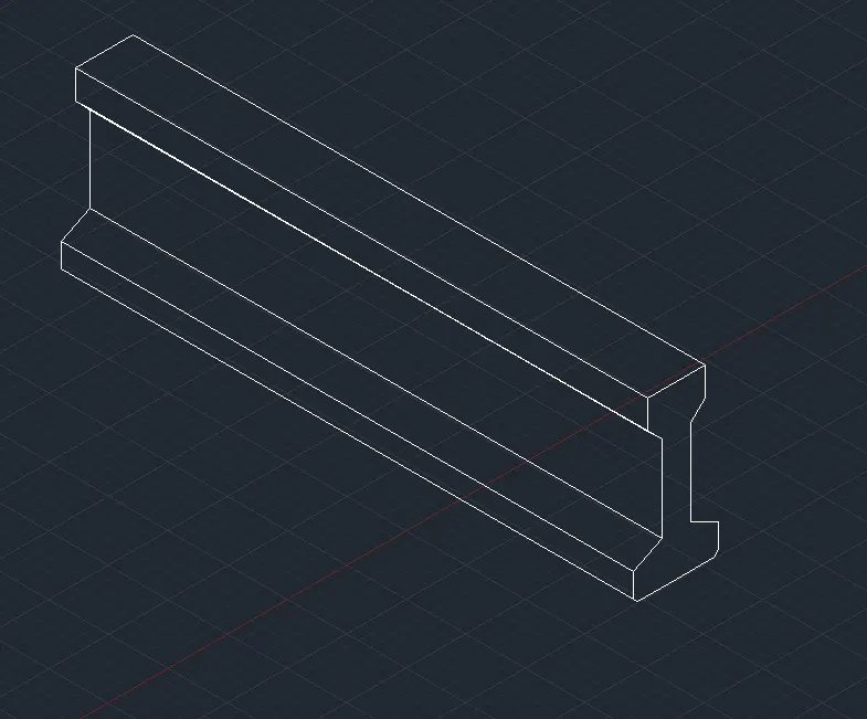
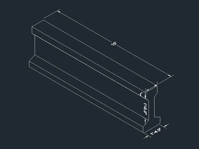
Results - A 3d View of AASTHO type Girder is created
i) 2d wireframe model
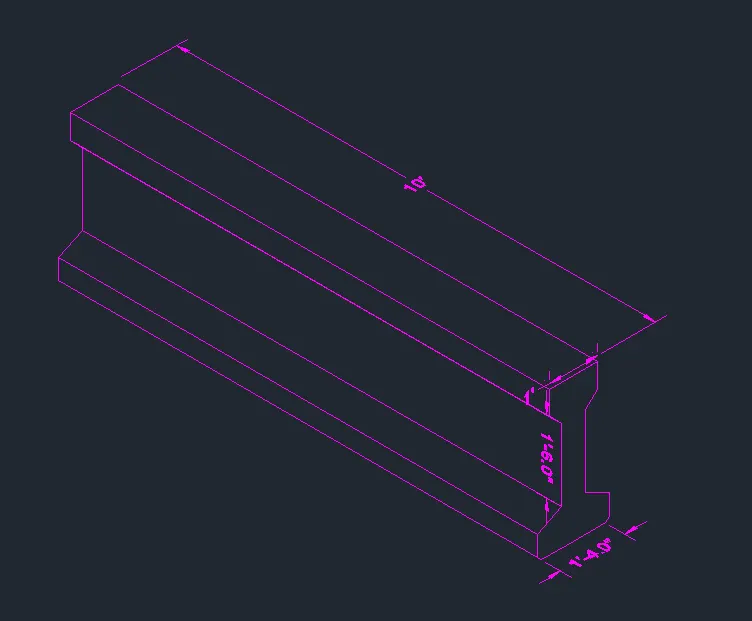
ii) Hidden
iii) Shaded
4)
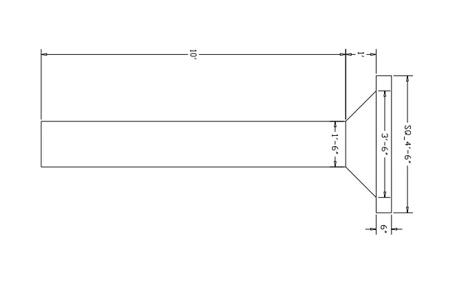
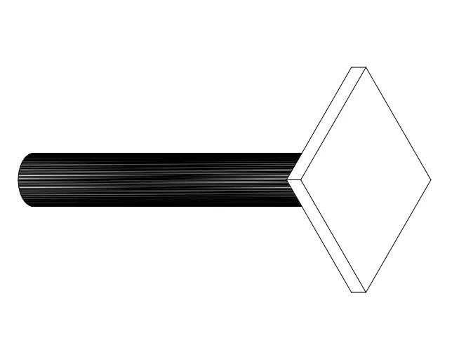
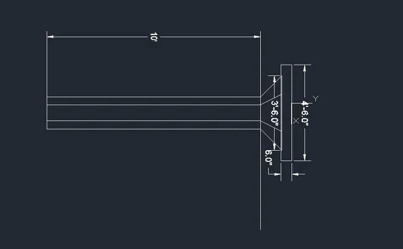
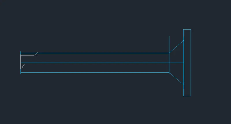
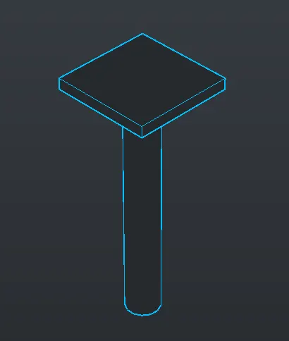
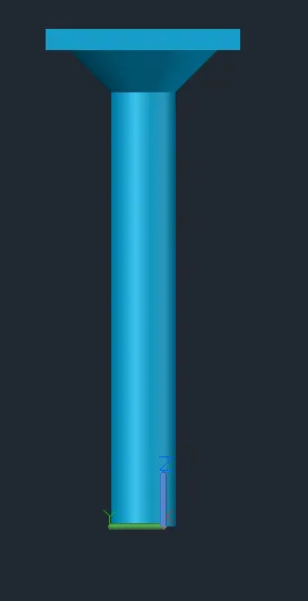
Aim - To creare 3D model of a drop column with panel as shown in section and isometric view.
Introduction - i) A drop column is generally used for flat slabs.
ii) In case of flat slab , Slab is directly resting on the columns . No beams are required if we are providing drop column
iii) Drop panel is an rectangular portion which are provided below the slab and above the column in order to restrict slab
from getting sheared .
iv) Drop panel increases the surfce area between slab and column and distribute the load uniformly .
v) Following Commands are used .
a) Line
b) Rectangle
c) Extrude
d) 3dMove
e) Circle
f) Dim
g) 3d faces
h) Region
Procedure -
i) Open a New drawing (Cntrl + N) select Imperical units ( Feet and Inches )
ii) Select units to Engineering and select precision as Inches (0'0.0")
iii) Command DS / Drafting settings - Change the Snap spacing and Grid spacing 1' and Change major lines
every grid to 5 .
iv) Change the workspace setting from Drafting and Annotations to 3D Modeling .
Step by step Procedure
Step 1)
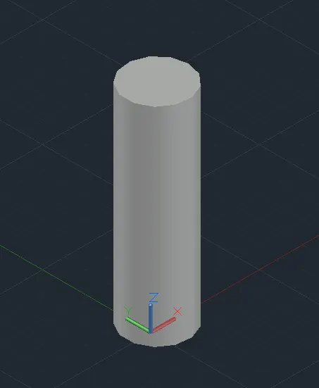
i) Command Circle
ii) Create a circle of Diameter - 1'6"
iii) Command Region
iv) Select the circle and Press enter .
v) Command Extrude .
vi) Select the object and Extrude at an height of 10' .
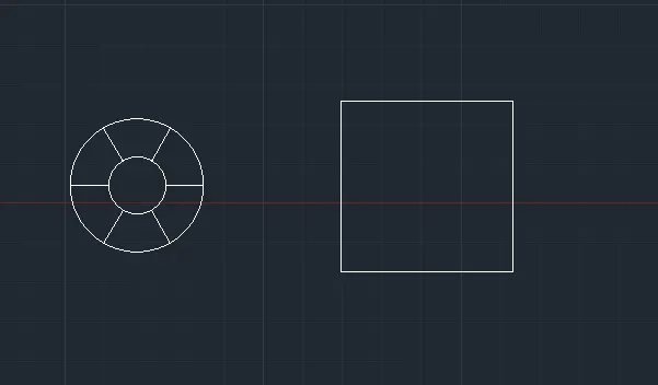
Step 2) Upper Portion
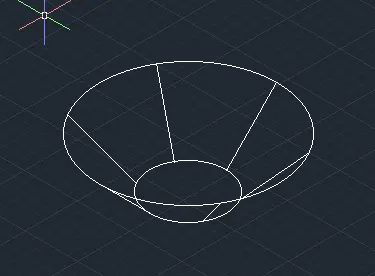
i) In Ribon Panel - Home - Box - Cone
ii) Select the cone
iii) Specify the base point and enter the base diameter as 1'6"
iv) Enter the Ht = 1'
v) Enter the Top Diameter as = 3'6"
Step 3)
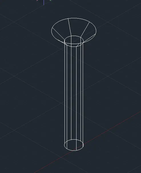
i) Now Command 3dMove -
ii) Move the cone by selecting the base point as center
iii) And move it the column by specifying the center point of column .
Step 4)
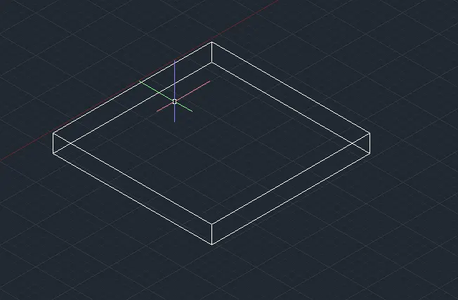
i) Now we have to create a rectangle
ii) Command Rectangle
iii) Enter Length = 4'6"
iv) Enter Width = 4'6"
v) And Extrude the Rectangle
vi) by giving Command Extrude at an height of 6"
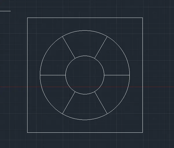
Step 5)
i) Now we have to place this rectangle to the top of the Panel head
ii) For the Change the View to Top
iii) Command 3dmove
iv) Take the Center the point of rectangle and move it to the Column head .
iv) Go to home view and see the 3d view
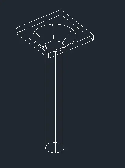
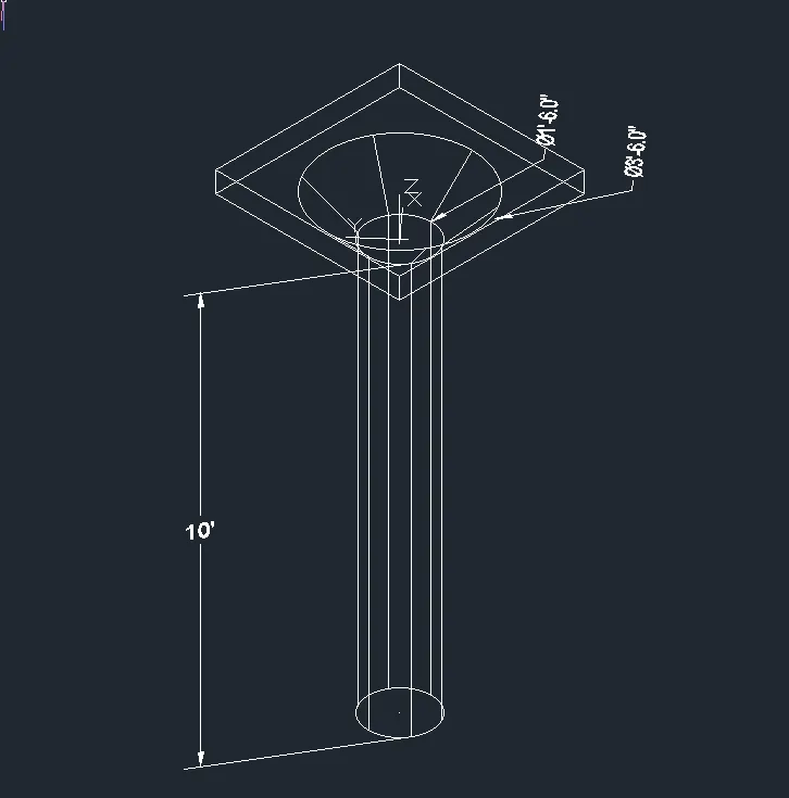
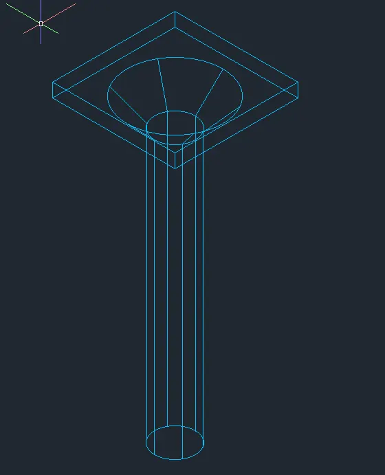
Results - A 3D view of given drop column with panel is drawn and Section as well as Isometric view are also shown
i) Section View
ii) Isometric View -
iii) 2D wireframe model -
iv) Hidden

v) Shaded -

5)
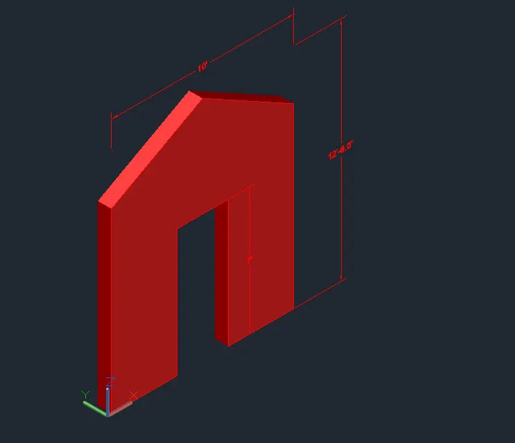
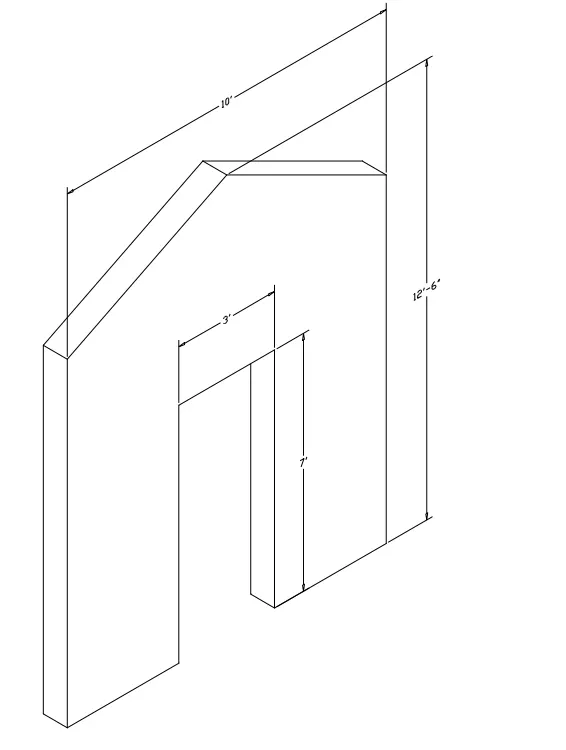
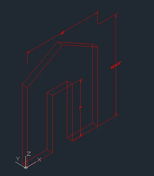
Aim - To create the 3d model of a wall having thickness as 9"
Introduction - i) A 3d view of wall is given in fig
ii) Thickness of wall is given as 9"
iii) A door opening is provided in a wall which is having dimensions 3'' x 7"
iv) i3D wireframe model can be drawn by using various coordinate sysrtem
v) Following Commands are used -
a) Line
b) Rectangle
c) Region
d) Extrude
e) Dim
Procedure -
i) Open a New drawing (Cntrl + N) select Imperical units ( Feet and Inches )
ii) Select units to Engineering and select precision as Inches (0'0.0")
iii) Command DS / Drafting settings - Change the Snap spacing and Grid spacing 1' and Change major lines
every grid to 5 .
iv) Change the workspace setting from Drafting and Annotations to 3D Modeling .
Step by Step Procedure -
Step 1)
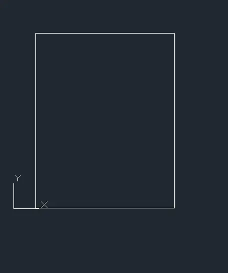
i) Change the View to Top View
ii) Command Rec -
iii) Enter Length = 10'
iv) Enter width = 12'6"
Step 2)
i) From the Mid point of the rectangle draw the line
ii) Command line
iii) Take the Mid point
iv) Draw a vertical line @0,7'
v) and to show the door opening
vi) Take the same midpoint and draw the horizontal line of 1.5' on both sides
vii) Take the midpoint of remaining gap between top of the wall and the top of door .
viii) For that draw a vertical and join both the top
ix) place the cursor and will get a midpoint of that line
x) Draw a horizontal line on both side from the midpoint .
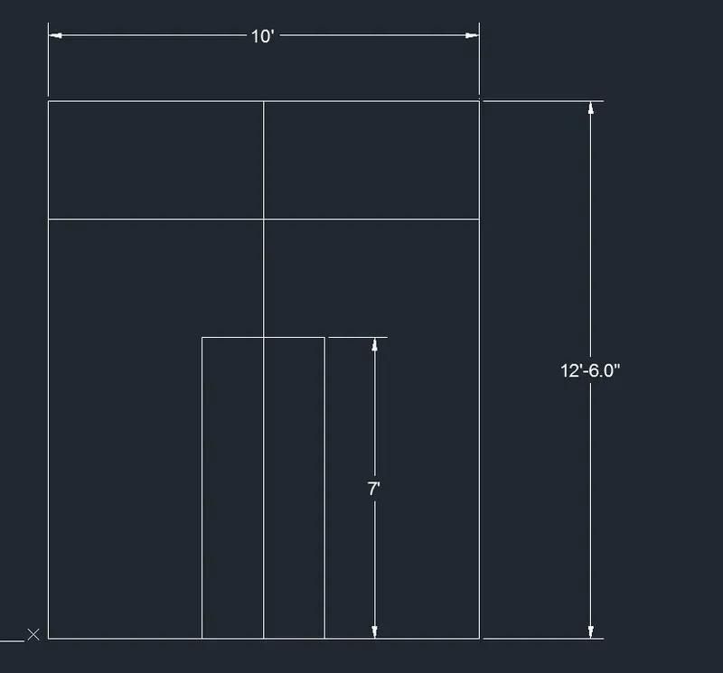
xi) Join the edges of the rectangle
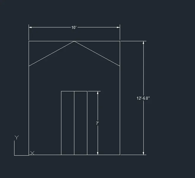
xii) Remove the unwanted lines
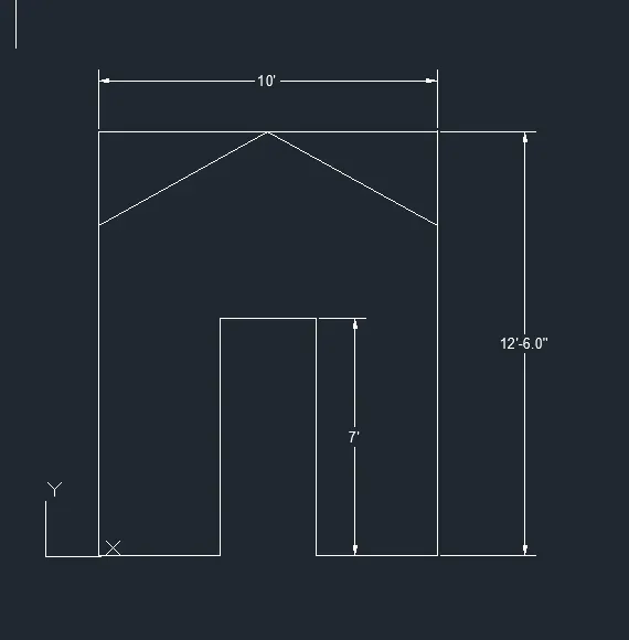
Step 3)
i) Change the view from top to the 3D
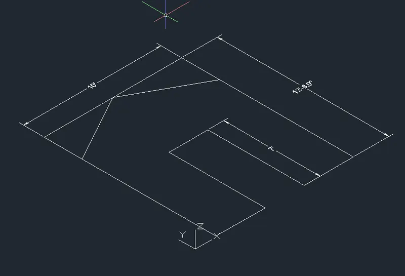
ii) Command Region -
iii) Select the Entire object and Press Enter
iv) Command Extrude -
v) Select the object and give the distance of 9"
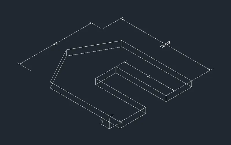
Results - A 3d view of wall is created
i) 2d wireframe model -
ii) Hidden
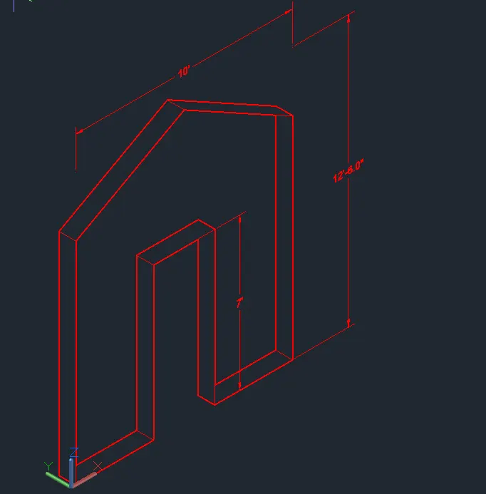
iii) Shaded