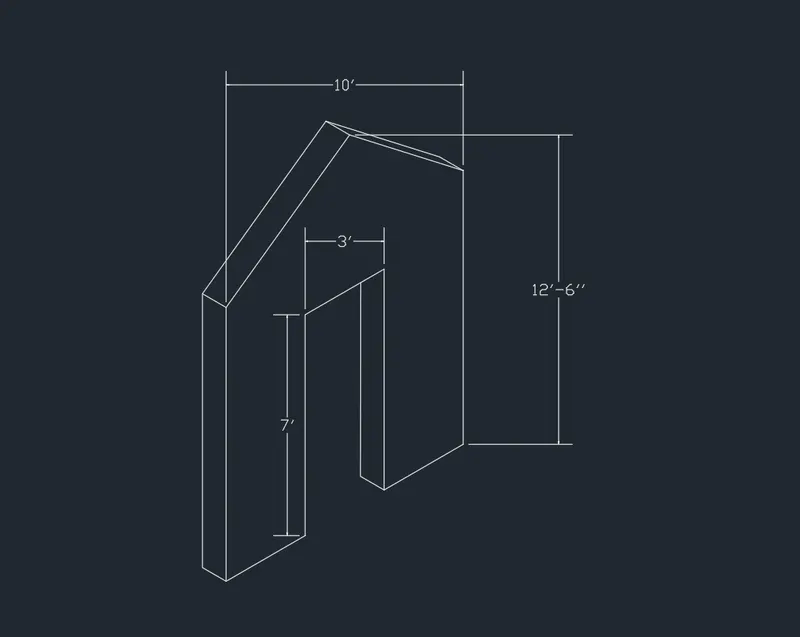
Creating various 3D Models like Furniture, Footing, Girder, Column drop with panel and Gable Wall in AutoCad
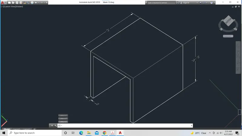
1.3D FURNITURE ELEMENT
AIM
To create the 3d element as shown in challenge
STEPS
- Open autoCAD new drawing in setting switch to 3dmodelling
- Select solids in ribbon then select box
- Set origin create box of dimension x = 3', y = 2'6'', z = 2'6''
- 3d solid will be created
- Then select shell, then select remove face, then select the corresponding face and then give thickness of 2''
- Then select the solid face and assign ucs
- Then give dimensions.
RESULT
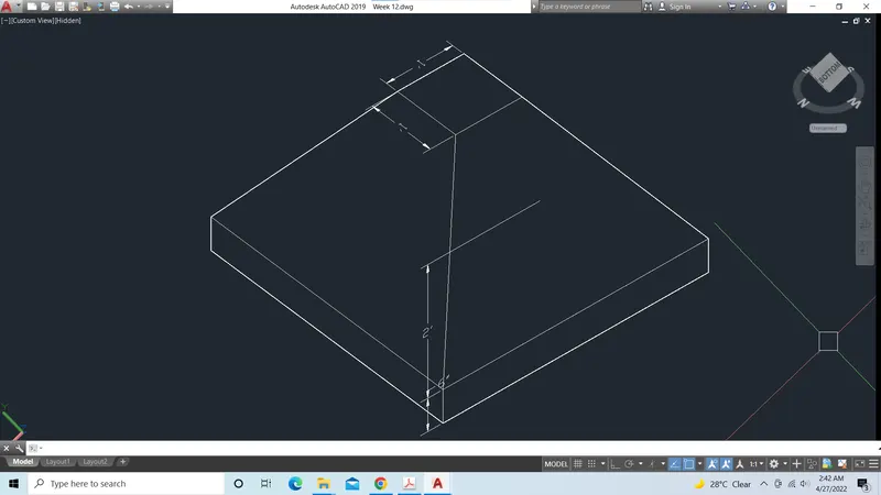
2.3D ISOLATED FOOTING
AIM
To create the 3d element as shown in challenge
STEPS
- Open autoCAD new drawing in setting switch to 3dmodelling
- Assign UCS, draw square of size 4' in xyplane at origin
- Then draw square of size 1' using offset of distance 1'6''
- Then copy the big square at distance of 0'6 in z axis
- Then move the small square at a distance of 2'6 in z axis
- Join the corresponding edges
- Then select the drawing and give REGOIN command
- Then select the corresponding face and give dimensions
RESULT
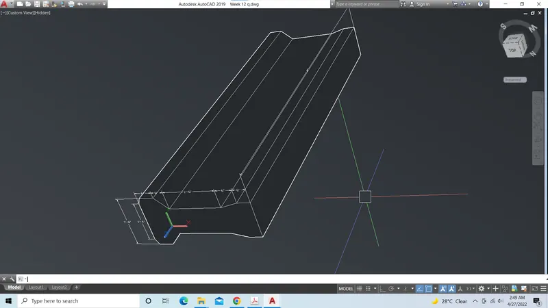
3.3D AASTHO GRIDER
AIM
To create the 3d element as shown in challenge
STEPS
- Open autoCAD new drawing in setting switch to 3dmodelling
- Assign UCS, draw grider in XY plane, by using angle coordinate system distance and angle
- Then draw line of distance 10' in Z axis
- Then command extrude and then select path and select line as path
- Then select the corresponding face and give dimensions
RESULT
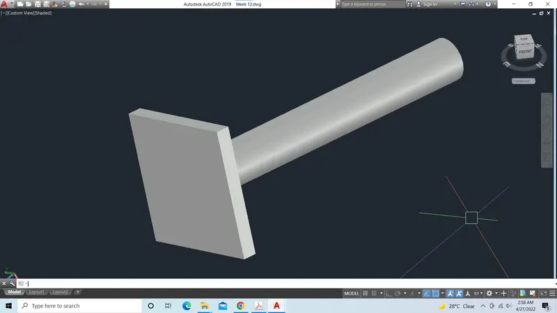
2.3D COLUMN WITH DROP PANEL
AIM
To create the 3d element as shown in challenge
STEPS
- Open autoCAD new drawing in setting switch to 3dmodelling
- Assign UCS, draw square of size 4'6'' in xyplane at origin
- Then copy the square at distance of 0'6 in z axis
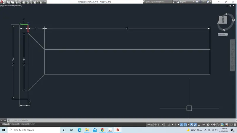
- Then draw the truncated cone with top radius 1'6'' and bottom radius 3'6 of height 1' from the geometric centre of square at top face
- Then draw circle over the cone of radius 1'6
- Then draw the line of distance 10'
- Then extrude the circle using path mode
- Generate section of 3D model
- Then give dimension
RESULT
2.3D WALL
AIM
To create the 3d element as shown in challenge
STEPS
- Open autoCAD new drawing in setting switch to 3dmodelling
- Assign UCS, Wall can be drawn by using isometric drafting, angle coordinate system, or polysolid method
- Here isometric drafting was used to create 3D wall
- Draw line with correponding dimension by switching the isometric right and left plane
- Then give dimension
RESULT