Creating Levels, Grids, Layout and model elements for a residential unit using REVIT
1) What is BIM? Summarize the features of BIM and benefits of using BIM over 2D CAD tools.
ans :
Building Information Modeling (BIM) is the foundation of digital transformation in the architecture, engineering, and construction (AEC) industry. As the leader in BIM, Autodesk is the industry's partner to realize better ways of working and better outcomes for business and the built world
BIM is an acronym for BUILDING INFORMATION MODELING or BUILDING INFORMATION MANAGEMENT.
It is a highly collaborative process that allows architects , engineers , real eastate developers , constractors , manufacturers , and other construction professionals to plan , design , and construct a structure or building with in one 3D model.
LEVELS IN BIM :
Different levels of BIM can be achieved for various types of projects.
Each level represents a different set of criteria that demonstrates a particular level of maturity.
BIM levels start with 0 and go to 4D , 5D , and even 6D BIM.
The purpose of these levels is to gauge how effectively , or how much information is being shared and managed throughout the entire process.
- LEVEL 0 BIM :
Paper - based drawings + zero collaboration - LEVEL 1 BIM :
2D construction drawing + some 3D modeling - LEVEL 2 BIM :
Teams work in their own 3D model - LEVEL 3 BIM :
Teams work with a shared 3D model - LEVEL 4 BIM :
Adding in scheduling
BIM level 4 brings a new element into the information model: time. This information includes scheduling data that helps outline how much time each phase of the project will take or sequencing of various components. - LEVEL 5 BIM :
Adding in cost
Level 5 BIM adds cost estimations, budget analysis, and budget tracking to the information model. When working at this level of BIM, project owners can track and determine what costs will be incurred during the length of the project. - LEVEL 6 BIM :
Adding in sustainability information.
Level 6 BIM information is useful for calculating the energy consumption of a building before it's built. This ensures that designers take into account more than just the upfront costs of an asset. Level 6 BIM ensures accurate predictions of energy consumption requirements and empowers stakeholders to build structures that are energy efficient and sustainable.
Benefits of Levels 4, 5, and 6 BIM:
More efficient site planning and scheduling
More efficient hand-offs between steps in the construction stage
Real-time cost visualization
Simplified cost analysis
Reduced energy consumption in the long run
Better operational management of the building or structure after handover
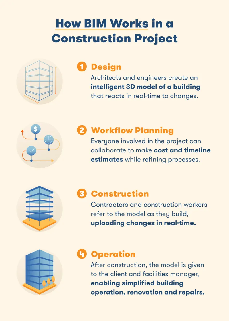
Building information modeling is useful at every stage of a construction project, including:
Design:
Using a model, architects and engineers can test out potential designs and identify problems immediately.
Planning:
Referencing the model, contractors can make estimates in cost and timeline and make improvements to the construction process.
Construction:
With the model always accessible, construction workers can clearly identify tasks and receive real-time updates about changes.
Operation:
After construction is complete, a facilities manager has access to the model, which is essentially an improvement over as-built drawings, showing all of the building’s features and systems.
BIM is used for creating and managing data during the design, construction and operations process. BIM integrates multi-disciplinary data to create detailed digital representations that are managed in an open cloud platform for real-time collaboration. Using BIM gives you greater visibility, better decision-making, more sustainable options and cost savings on AEC projects.
The process of BIM
The process of BIM supports the creation of intelligent data that can be used throughout the lifecycle of a building or infrastructure project.
- Plan
Inform project planning by combining reality capture and real-world data to generate context models of the existing built and natural environment. - Design
During this phase, conceptual design, analysis, detailing and documentation are performed. The preconstruction process begins using BIM data to inform scheduling and logistics. - Build
During this phase, fabrication begins using BIM specifications. Project construction logistics are shared with trades and contractors to ensure optimum timing and efficiency. - Operate
BIM data carries over to operations and maintenance of finished assets. BIM data can also be used down the road for cost-effective renovation or efficient deconstruction.
Some of the advantages of BIM in construction include:
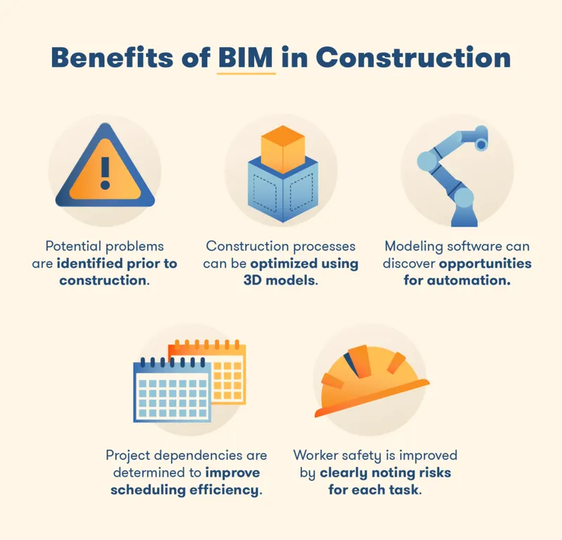
Early detection of problems:
Conflicting elements in a building’s design are identified during the modeling phase, preventing costly changes during construction.
Improvement in scheduling:
Project elements can be sequenced more efficiently using intelligent modeling, enabling the possibility for more systematic scheduling.
Construction automation:
Tasks that can be easily automated are identified by the software, leaving workers to focus on specialized tasks.
Enhanced construction processes:
Workflows are automatically generated by BIM software and any changes made during construction automatically update the process for everyone on site.
Increased worker safety:
Workers have direct access to specific information about each task, leading to increased awareness of risk and focus.
BIM is revolutionising the way projects are delivered across industries, adding intelligence and efficiency to project execution – and connecting teams, data and workflows at every stage of the project in the cloud for better project outcomes.
The difference between Revit and BIM is that BIM is a process – a methodology – for project teams to interface with technology to deliver better project outcomes in the AEC market, while Revit is a software platform designed to facilitate that process. The tools in Revit are specifically designed to support BIM, allowing users to create a structured, intelligent model with information stored in it.
The difference between 3D CAD modelling and BIM is that, while both processes provide geometric expressions of buildings and infrastructure, the BIM process goes beyond geometry to capture the relationships, metadata and behaviours intrinsic to real-world building components. Combined with technology of the BIM ecosystem, this data drives improved project outcomes in a way that 3D modelling cannot.
Both CAD and BIM processes are used to capture and communicate the design and construction intent of an AEC project using a drawing representation, helping stakeholders understand what needs to be built, and how. BIM enables design and construction teams to leverage their technology investment to do much more. The BIM process supports creation and management of information across the lifecycle of an AEC project by federating all multi-disciplinary design and construction documentation into a common dataset. Since that data can be accessed in multiple representations, from 2D to 3D to tables, the information is far more accessible and connected than the disparate data sources associated with traditional CAD approaches.
DIFFERENCE BETWEEN 2D CAD AND BIM
Building information modeling (BIM) is a set of software tools that make it possible to visualize a design idea with realistic dimensions from a multitude of angles. With BIM, design teams and work crews can have a virtual experience of a building, road, bridge or monument before the structure is physically constructed. For all the parties involved in the conceptualization and construction of a structure — including earthworks and surveying crews — BIM provides the following benefits and features:
1. CONFLICT PREVENTION
BIM tools allow earthwork teams to determine whether any clashes might occur between a proposed design and the underlying conditions of the site in question. For example, if a building would need deep plumbing yet the ground being excavated sits over thick roots and rocks, these discoveries can be factored into the design plans to avoid issues down the line.
2. ERROR REDUCTION
BIM technology makes it possible to catch any errors that initially appeared in a proposed design before the construction work goes into effect. For example, if earthwork crews discover that the dimensions of a proposed building design will not be feasible at the prospective site, planning crews can take this information into account and either make adjustments or change the overall plan.
3. USE IN CONSTRUCTION
BIM software is used by construction crews who break grounds on new lands to establish the foundations of roads, highways, buildings, bridges, monuments and structures. The software makes it possible to determine which structures will ultimately work over certain types of soil, thus making the processes involved with earthworks easier for planners and crews.
4. USE IN GROUND LOGISTICS
BIM software contains a range of features that specifically outline the logistics of plumbing at a given work site. This way, planners can determine whether the stretch of land in question will be suited for the project at hand, be it a tall office building or a wide industrial facility.
5. USE IN PLANNING PIPING
BIM solutions make it possible for earthworks crews to determine which type of piping will suit the stretch of land in question. The software can be used to create 3D piping designs that take into account the diameters and lengths necessary to transfer water underneath a proposed building site to the nearest reservoir.
6. COLLABORATION TOOLS
BIM solutions offer collaborative tools that make it possible for earthworks teams to interact with other teams in the construction process, from designers and architects to builders, planners and investors. Collaboration tools include communication technology that works across different platforms, allowing cloud-based branches to interact with more traditional departments.
7. VISUALIZATION TECHNOLOGY
BIM tools make it possible to visualize a site in 3D and determine how a potential structure will appear from the ground up at a given site. Based on the position of the proposed structure, the tools allow earthworks and construction crews to determine how sunlight will hit the walls of the building or factory and potentially light its interiors.
8. STEP SEQUENCING
BIM software programs arrange the building process in a series of steps from the ground up, including the logistics involved for earthworks crews. The tools can be used to determine how wide the clearance will need to measure for a proposed structure and how deep the ground will need to be broken to support the height and plumbing needs of the building in question.
9. ADVANCED FEATURES
BIM solutions go beyond 3D technology to make a full-scale planning sequence for earthworks and developers. In new and upcoming versions of the software, BIM is activating tools in 4D, 5D and 6D, giving users the ability to visualize cost logistics in tandem with design concerns. These more advanced features also make it possible for users to determine the thermal and acoustic properties of a proposed building on the site in question.
POTENTIAL ISSUES WITH BIM SOFTWARE
On the downside, BIM has yet to be developed to the point of universal compatibility across all branches of the construction industry. Companies and crews that have fully embraced the technology may have problems communicating certain ideas, information and visuals with cooperating entities that still rely on older technology.
Due to the relative novel nature of BIM technology, expertise in BIM software is a relatively small field. Consequently, there are few technicians to consult when users need outside support on a given issue.
Computer-aided design (CAD) is a set of software tools that allow designers to create 2D and 3D virtual models of buildings, structures, machines and parts. For surveyors and earthworks crews, CAD makes it possible to review a proposed structure before commencing work on the ground. The features as well as pros and cons of CAD can be summarized as follows:
1. ENHANCED VISUALIZATION
CAD software makes it possible for designers and project developers to visualize a product or part in advance of its production. The software can be used to examine a proposed design from a variety of angles, both inside and out. Whereas conventional designs offer a flat illustration of a proposed idea, CAD makes it possible to step inside of a design and view it from a 360-degree perspective.
2. IMPROVED COMMUNICATION
CAD allows developers to communicate about the logistics and dimensions of a given design and make improvements as discoveries come to light. For earthworks crews in need of new tools and machines for an upcoming set of tasks, CAD provides an easy way for designers to communicate with team supervisors.
3. USE FOR STRUCTURAL ENGINEERING
CAD software accommodates the various aspects of structural engineering. Moreover, most CAD programs offer functionalities that apply to specific industries and the various branches that the projects entail. For projects that involve railroad, tunnel or freeway construction, the design features take all the dimensions into account as the design team drafts a 3D visual of the proposed structure, which earthworks teams can then examine and use to visualize the intended finished project.
4. USE IN EARTHWORKS LOGISTICS
When the design for a proposed building, road or bridge is created on a CAD platform, the visualizations that the technology provides makes it easier for earthworks crews to foresee how the finished structure will look from the ground up. This knowledge can then be compared to the findings of work teams as they survey the land in question and prepare to break ground.
5. ACCURATE DESIGN SPECS
CAD platforms make it possible for civil engineers to generate maps and analyze specs across a stretch of land. This research enables better-informed designs for railways and tunnels, thus reducing potential errors and costly redrafts down the line. This information can then be communicated to earthworks crews, making the overall plan more efficient and easier to bring to fruition.
6. INPUT AND FEEDBACK
CAD platforms allow conceptualists to take a raw idea and turn it into a three-dimensional design. This allows different branches of a development team to mutually review a proposed design idea and make suggestions that can easily be implemented. If an earthworks supervisor spots an issue with a proposed design, the designing engineer can immediately take this feedback into account.
7. ADVANCED TOOLS
CAD software comes equipped with various design tools that facilitate ease of use and also make it possible to achieve visualization effects that would not be possible with a flat illustration. For example, both 2D and 3D CAD software contains a gripping feature that allows designers to pull, alter, adjust and reshape the dimensions of a proposed structural concept. If an earthworks supervisor reports that a road or pavement design requires an adjustment in width, a grip tool can help employees quickly make those changes.
POTENTIAL ISSUES WITH CAD SOFTWARE
CAD software typical takes time to master, meaning that the cost of training can be high and the learning curve can be long. Moreover, the number of CAD experts is relatively small, which can make it difficult to find help if a problem arises.
For any company that has yet to migrate to a cloud server, CAD would be a step removed from that company’s technical infrastructure. As with most new technology, CAD is primarily designed for companies that are up to date on today’s more advanced systems.
A quick rundown of the features of BIM and CAD makes the two seem rather similar. So how do you compare BIM and CAD? The two have some crucial differences that make each more suitable for different types of projects. So what is the difference between BIM and CAD?
CAD was developed to design virtual models for everything from appliances and furnishings to automobiles and rolling stock. CAD software tools are used to create 3D visualizations of the surrounding bodies of vehicles and tools, as well as the smaller parts that comprise the motors and fans inside each machine.
CAD can be thought of as a computerized sketchbook in which designs are hashed out and ultimately refined in 2D and 3D renderings. Each line works independently of one another and can be adjusted or eliminated without affecting any of the surrounding or underlying lines in the design. Therefore, if the design for a parking lot or road requires an extra three feet on one side, you can adjust the line that represents that side accommodate the change in dimensions.
Complex CAD designs consist of numerous sheets, each with separate lines that are overlaid in a virtual file. If a design needs to be adjusted, you must adjust all the layers affected by this change individually. If a design consists of many layers that must each be adjusted in tandem with the others, making revisions can be complicated. With CAD, there is no way to synchronize the layers into a single-action item for a multi-layer adjustment.
BIM was developed more exclusively for the virtual design and multi-dimensional visualization of proposed building ideas. As such, the tools are designed to digitally render the complex dimensions of all the parts that comprise the interior and exterior of a residence, factory or office building, including the walls, stairs, doors, windows, ceilings, plumbing, wiring, lighting and ventilation.
A major difference between BIM and CAD is the interactivity of the different dimensions during the editing process. In BIM, the dimensions that comprise an object are interconnected. Therefore, any adjustment that needs to be made in a building design, such as the width of a wall or corridor, can be done in a single edit.
In BIM, the dimensions of a given detail can be synchronized to all instances of the detail in question. For example, if the windows on a building are initially designed to be 3.5’x5’ and need to be adjusted to 4’x5’, you can change all the windows on the virtual building with a single adjustment.
IN THIS CASE REVIT ADOPTS THE BIM AND CREATE A SPECIAL ATTRACTION FOR MAKING THE CONSTRUCTION , DESIGN , ANALYSIS SIMPLE LIKE USING THE FOLLOWING FEATURES :
- REALTIME CHANGES
- EVALUATION OF PERFORMANCE
- OPTIMIZATION
- SUSTAINABILITY
- PARAMETRIC DESIGN
2) Understand the concept of Categories, Families, Elements, Instances in Revit. Go to Insert Tab, choose a category. Pick a family and element. Understand the instances and insert it to Revit model
ans :
- CATEGORY :
A CATEGORY CONTROLS THE ORGANIZATION , VISIBILITY , GRAPHICAL REPRESENTATIONS , AND SCHEDULING OPTIONS OF FAMILIES WITH IN THE PROJECT. - FAMILY :
A FAMILY IS A GROUPING OF 2D AND 3D INFORMATION THAT SERVES TO REPRESENT A DISCRETE BUILDING OR DOCUMENTATION ELEMENTS IN THE PROJECT.
IT DEFINES PARAMETRIC , GRAPHICAL , AND DOCUMENTATION REQUIREMENTS. - THERE ARE 3 KINDS OF REVIT FAMILIES
1) SYSTEM FAMILIES
2) LOADABLE FAMILIES
3) IN-PLACE FAMILIES
1) SYSTEM FAMILIES :
THESE ARE THE FAMILIES THAT ARE PRE-DEFINED FAMILIES SPECIFIC TO A REVIT PROJECT.
THEIR PARAMETRIC , GRAPHICAL , AND DOCUMENTATION REQUIREMENTS ALREADY EXIST.
THEY CAN NOT BE CREATED IN , DELETED FROM , LOADED INTO , OR SAVED OUT OF THE CURRENT PROJECT.
2) LOADABLE FAMILIES :
THESE ARE THE FAMILIES THAT ARE USER-DEFINED FAMILIES BUILT IN AN EDITING MODE CALLED THE FAMILY EDITOR USING FAMILY TEMPLATES.
THEIR PARAMETRIC , GRAPHICAL , AND DOCUMENTATION REQUIREMENTS CAN BE DEFINED FROM SCRATCH.
THEY CAN BE CREATED AND LOADED INTO A PROJECT AS WELL AS , DELETE OR SAVED FROM A PROJECT.
3) IN-PLACE FAMILIES :
THESE ARE THE FAMILIES THAT ARE USER-DEFINED FAMILIES CREATED TO REPRESENT A ONE OF A KIND ELEMENT UNIQUE TO THE PROJECT.
LIKE SYSTEM FAMILIES THEY CANNOT BE LOADED INTO OR SAVED OUT OF A PROJECT BUT , THEY CAN BE CREATED WITH IN THE CONTEXT OF THE PROJECT USING FAMILIAR FAMILY EDITOR TOOLS.
- TYPE :
A TYPE IS A SPECIFIC REPRESENTATION IN A FAMILY DEFINED BY DISTINCT PARAMETRIC , GRAPHICAL , AND DOCUMENTATION CHARACTERISTICS WHICH MAKES IT UNIQUE FROM OTHER TYPE IN THE FAMILY.. - INSTANCE :
AN INSTANCE IS AN INDIVIDUAL REPRESENTATION OF A TYPE IN THE PROJECT DEFINED BY UNIQUE PARAMETRIC , GRAPHICAL , AND DOCUMENTATION CHARACTERISTICS WHICH MAKES IT UNIQUE FROM OTHER INSTANCES IN THE PROJECT.
AIM : TO CREATE A FAMILY IN REVIT
PROCEDURE :
STEP 1 : TO OPEN REVIT TOOL
OPEN REVIT SOFTWARE BY USING REVIT ICON
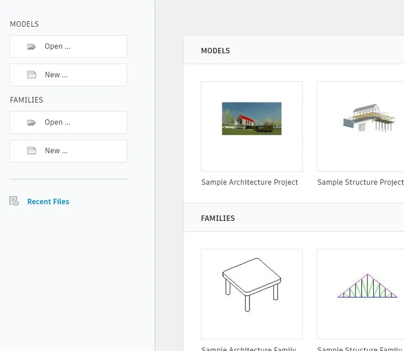
GO TO NEW
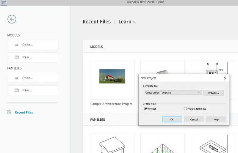
SCELET TEMPLATE FILE AS ARCHITECTURAL TEMPLATE
SCELET CREATE NEW AS PROJECT
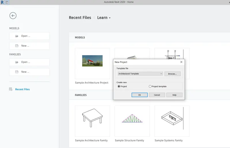
FINALY CLICK ON OK
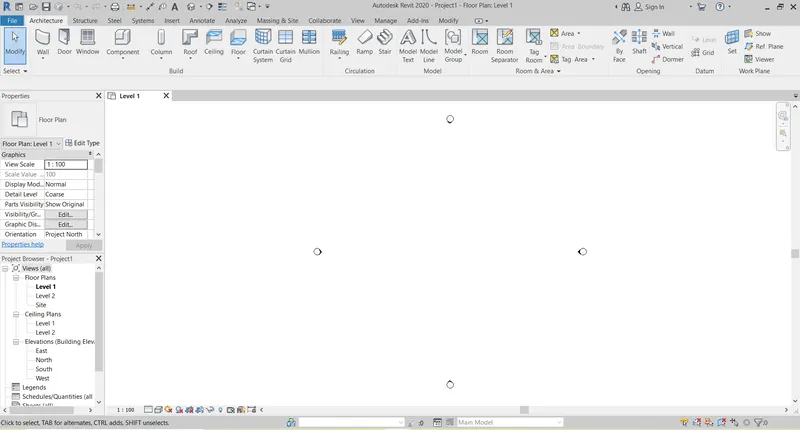
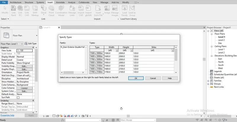
STEP 2 : TO LOAD THE FAMILIES
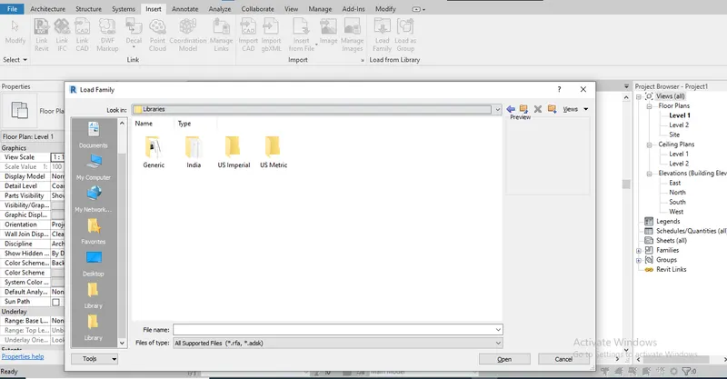
GO TO INSERT TAB AS SHOWN BELOW
CLICK ON LOAD FAMILIES
FROM THE POP-UP BOX SELECT LABRARIES
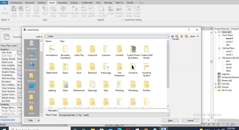
GO TO INDIA
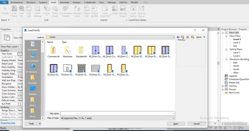
GO TO DOORS / WINDOWS / OR AS YOUR REQUIRED FAMILIES
GO TO RESIDENTIAL TYPE
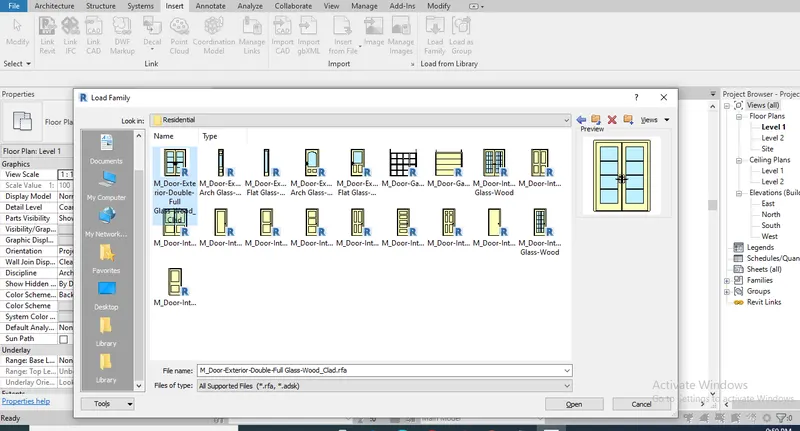
CLICK ON DOOR TYPE
FINALY CLICK ON OPEN
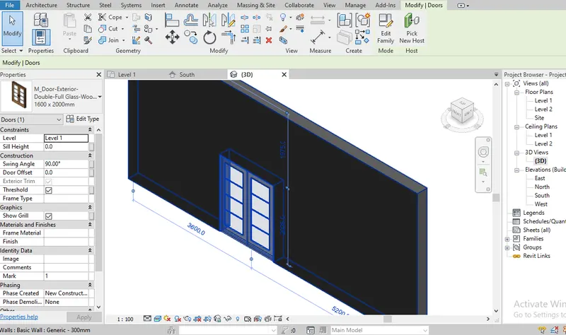
PLACE THE DOORS OR ANY FAMILIES ARE AS YOUR REQUIRED AREA
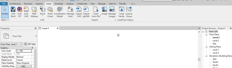
OR
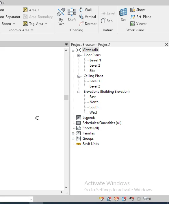
PROJECT BROWSER
FAMILIES ARE ALSO BE ADDED FROM THE PROJECT BROWSER ALSO
GO TO PROJECT BROWSER
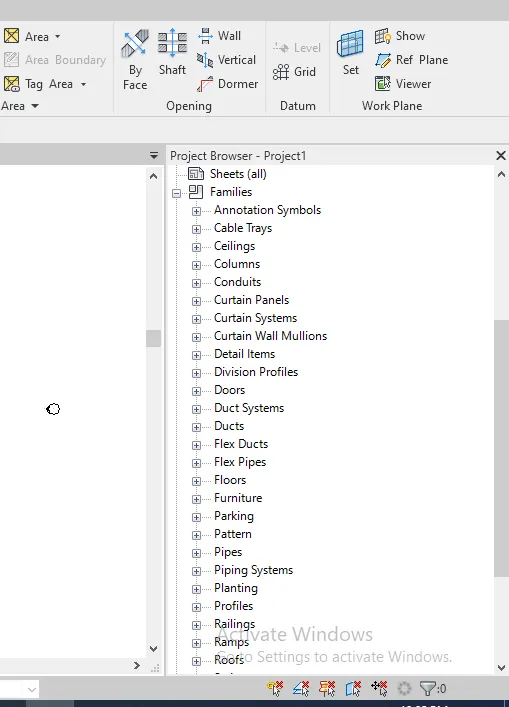
IN GO TO FAMILIES [ + ]
GO TO DOORS / WINDOWS / OR AS YOUR REQUIRED FAMILIES
GO TO RESIDENTIAL TYPE
CLICK ON DOOR TYPE
CLICK ON DRAG THE REQUIRED FAMILIES
PLACE THE DOORS OR ANY FAMILIES ARE AS YOUR REQUIRED AREA
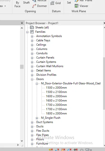
RESULT :
TO LOADED FAMILIES
3) Setting up a Project – Open a project file with architectural template. Save the file with appropriate name. Set up the project units to Imperial / Metric based on your convenience of modelling. Complete the project information under Manage tab. Set up the maximum backups for project file to 3
ans :
AIM : TO SET UP A PROJECT
PROCEDURE :
STEP 1 : TO OPEN REVIT TOOL
OPEN REVIT SOFTWARE BY USING REVIT ICON
GO TO NEW
SCELET TEMPLATE FILE AS ARCHITECTURAL TEMPLATE
SCELET CREATE NEW AS PROJECT
FINALY CLICK ON OK
STEP 2 : PROJECT UNITS
GO TO MANAGE TAB
GO TO PROJECT UNITS ICON
OR
CLICK ON PROJECT UNITS COMMAND IS UN TYPE THE KEYBOARD
OPEN THE PROJECT UNITS POP UP
CHANGE THE UNITS ARE AS YOUR REQUIRED PROJECT UNITS / BASED ON YOUR PROJECT DOING
FINALY CLICK ON OK
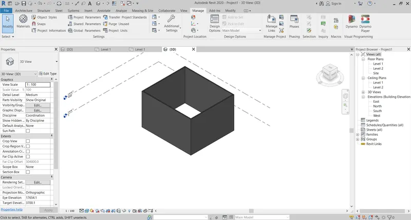
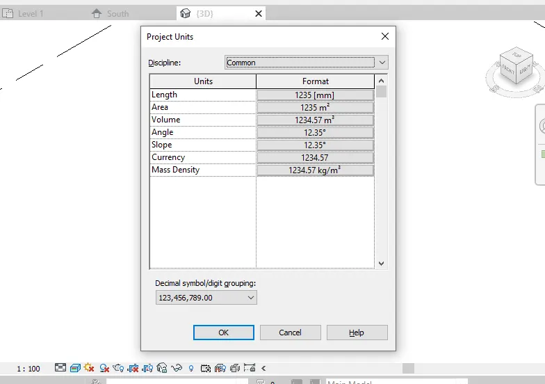
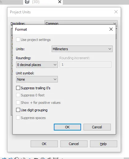
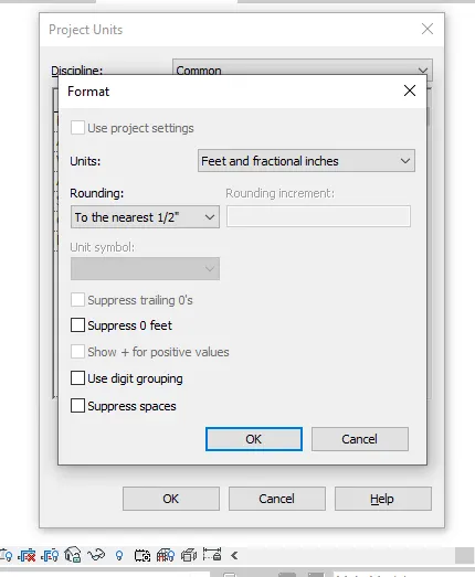
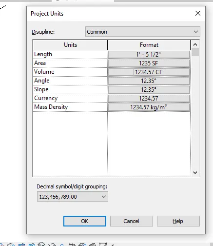
STEP 3 : PROJECT INFORMATION
GO TO MANAGE TAB
GO TO PROJECT INFORMATION
THEN OPEN THE PROJECT INFORMATION DIALOGUE BOX
CHANGE THE UNITS ARE AS YOUR REQUIRED PROJECT UNITS / BASED ON YOUR PROJECT DOING
FINALY CLICK ON OK
CLICK ON MANAGE TOOL TO OPEN THE MANAGE TOOL BAR
NOW WE WILL FIND PROJECT INFORMATION ICON UNDER SETTINGS SECTION IN MANAGE TOOL BAR
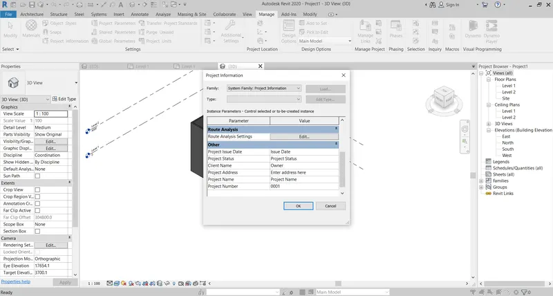
BY CLICKING THE PROJECT INFORMATION TOOL , A DIALOGUE BOX IS OPENED WE CAN ENTER NAME , ISSUED DATE AND PROJECT SETTING AND CLICK OK
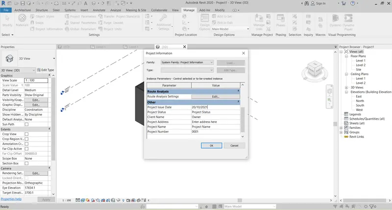
STEP 4 : SAVE AND MAXIMUM BACKUP AS 3
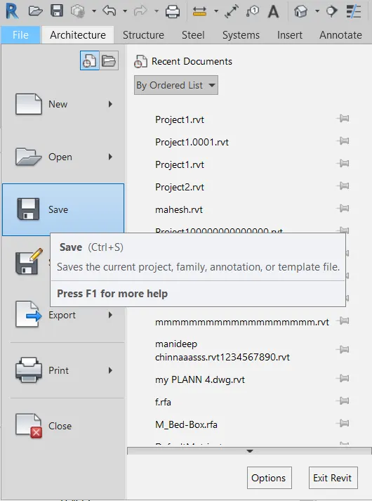
GO TO FILE TAB
THEN CLICK ON SAVE
OR
CLICK ON KEYBOARD PRESS CTRL + S
GIVE THE FILE NAME
THEN GO TO OPTIONS
GIVE THE MAXIMUM BACKUP AS 3
FINALY CLICK ON OK
FINALY CLIC ON SAVE
GO TO FILE TOOLBAR
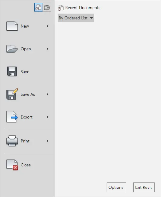
CLICK ON THE SAVE OPTION
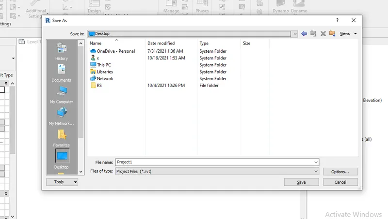
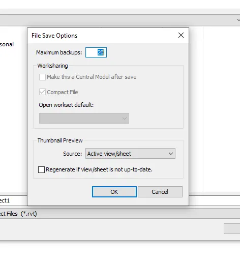
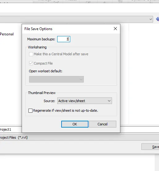
RESULT :
INITIALLY THE PROJECT IS SAVED WITH AN APPROPRIATE NAME AND ALSO THE MAXIMUM BACKUPS FOR PROJECT FILES TO 3.
THE RESULT AFTER ENTERING THE PROJECT UNITS AND PROJECT INFROMATION SUCH AS PROJECT NAME , PROJECT ISSUE DATE , PROJECT STATUS , PROJECT NUMBER.
PROJECT INFORMATION
PROJECT UNITS
SAVE AND MAXIMUM BACKUP AS 3
4) Understand the concept of Levels and Grids. Follow the naming and conventions. Create the following Levels: ( Convert to metric equivalents if metric is your units)
Ground Floor @ 0’
First Floor @ 10’
Second Floor @ 20’
Roof @ 30’
Grids Transverse Grids A, B,C,D, E @ 10’ spacing
Longitudinal Grids from 1 to 10 @ 20’ spacing
ans :
AIM : TO CREATE LEVELS AND GRIDS FOR STANDARD LAYOUT
PROCEDURE :
STEP 1 : TO OPEN REVIT TOOL
OPEN REVIT SOFTWARE BY USING REVIT ICON
GO TO NEW
SCELET TEMPLATE FILE AS ARCHITECTURAL TEMPLATE
SCELET CREATE NEW AS PROJECT
FINALY CLICK ON OK
STEP 2 : PROJECT UNITS
GO TO MANAGE TAB
GO TO PROJECT UNITS ICON
OR
CLICK ON PROJECT UNITS COMMAND IS UN TYPE THE KEYBOARD
OPEN THE PROJECT UNITS POP UP
CHANGE THE UNITS ARE AS YOUR REQUIRED PROJECT UNITS / BASED ON YOUR PROJECT DOING
FINALY CLICK ON OK
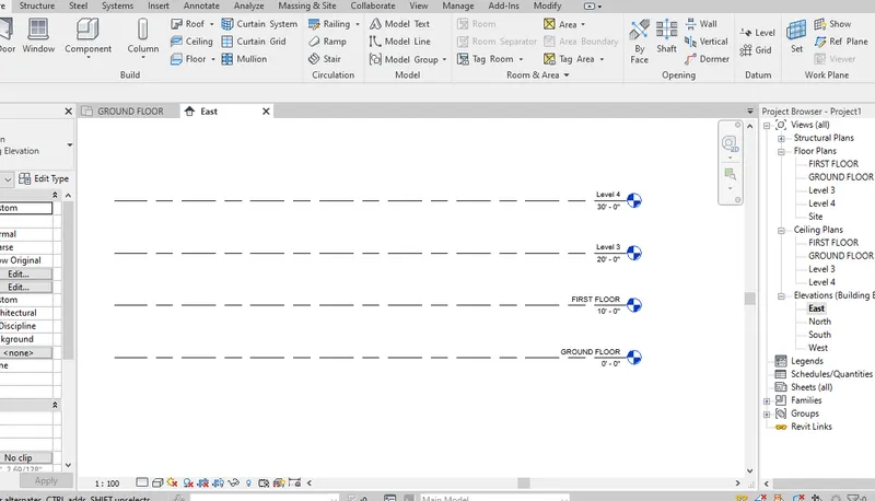
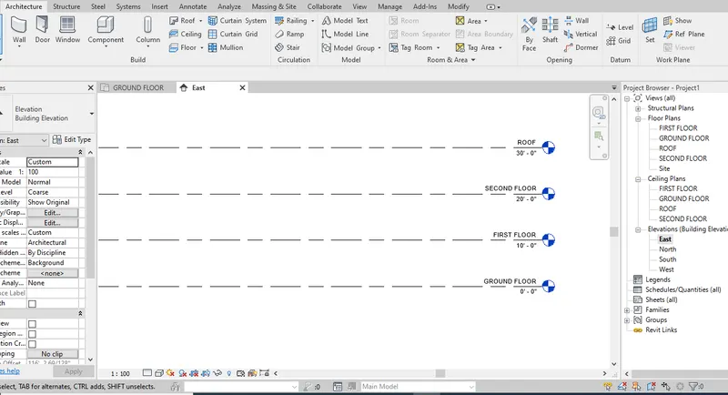
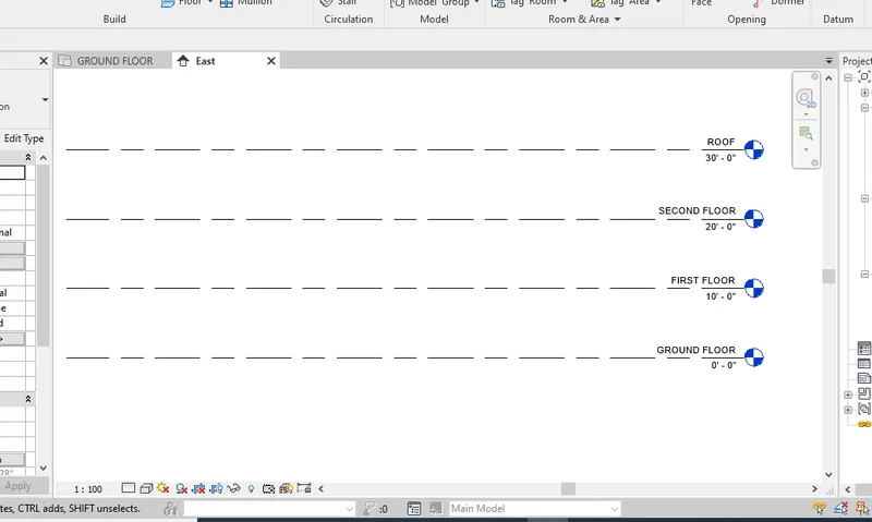
STEP 3 : TO CREATE LEVELS
TO CREATE LEVELS AS REQUIRED AS
GROUND FLOOR AT 0'
FIRST FLOOR AT 10'
SECOND FLOOR AT 20'
ROOF AT 30'
GO TO ANY ONE ELEVATIONS VIEWS
TO CHANGE THE LEVEL 1 AND LEVEL 2 HEGHIT FOR 10' AND AS WELL AS NAME AS LEVEL 1 IS GROUND FLOOR AND LEVEL 2 IS FIRST FLOOR
NEXT TO TAKE THE LEVEL OPTIONS
GO TO ARCHITECTURAL TAB
THEN GO TO DATUM
THEN TAKE LEVELS OPTIONS
OR
LEVELS OPTIONS KEYBOARD SHORT KUT IS LL PRESS
DRAW THE LEVELS AS YOUR REQUIRED AT
SECOND FLOOR AT 20'
ROOF AT 30'
AS WELL AS TO CHENGE THE NAME AS REQUIRED ABOVE NAMES
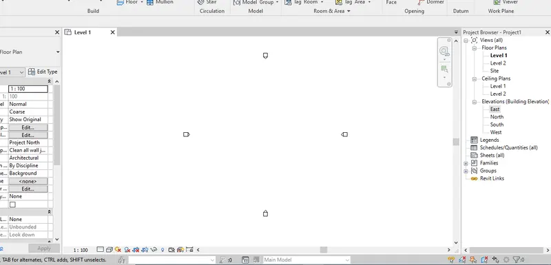
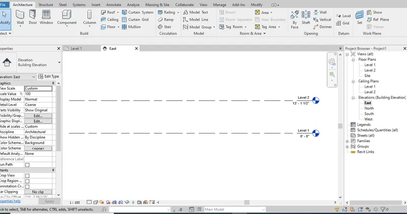
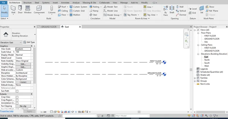
NOW
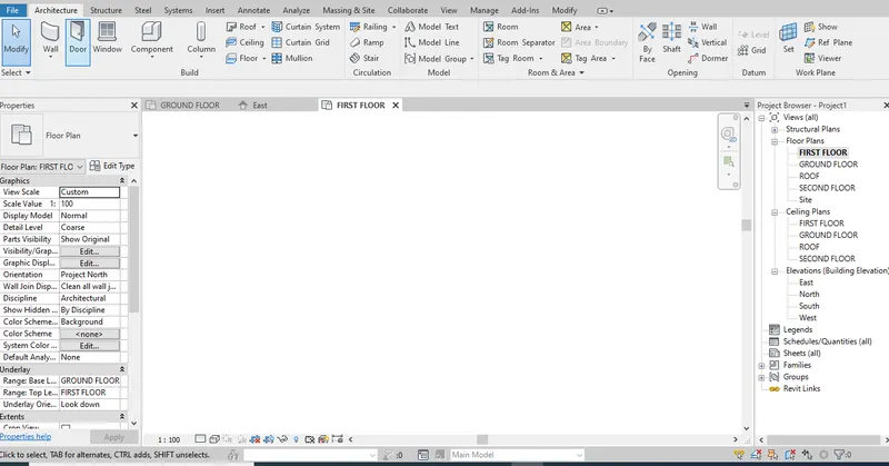
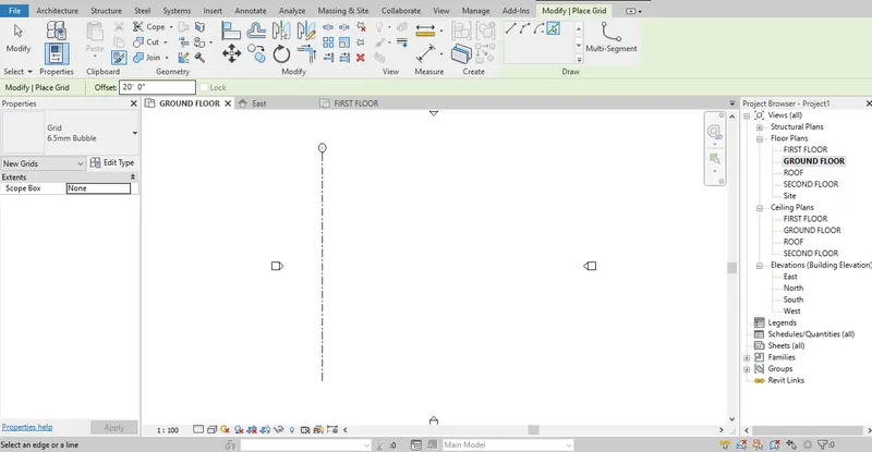
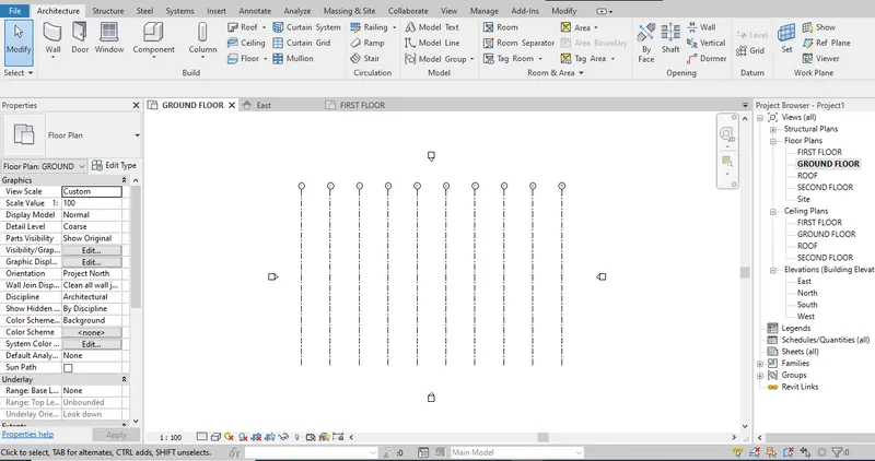
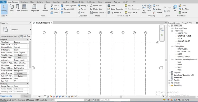
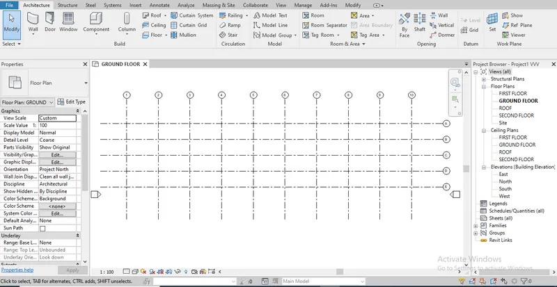
STEP 4 : TO CREATE GRIDS
TO CREATE THE GRIDS AS YOUR REQUIRED
GRIDS TRANSVERSE GRID A , B , C , D , E AT 10' SPACING
GRIDS LONGITUDINAL GRID FROM 1 TO 10 AT 20' SPACING
GO TO FIRST FLOOR PLAN
GO TO ARCHITECTURAL TAB
THEN GO TO DATUM
THEN TAKE GRIDS OPTIONS
OR
GRIDS OPTIONS KEYBOARD SHORT KUT IS LL PRESS
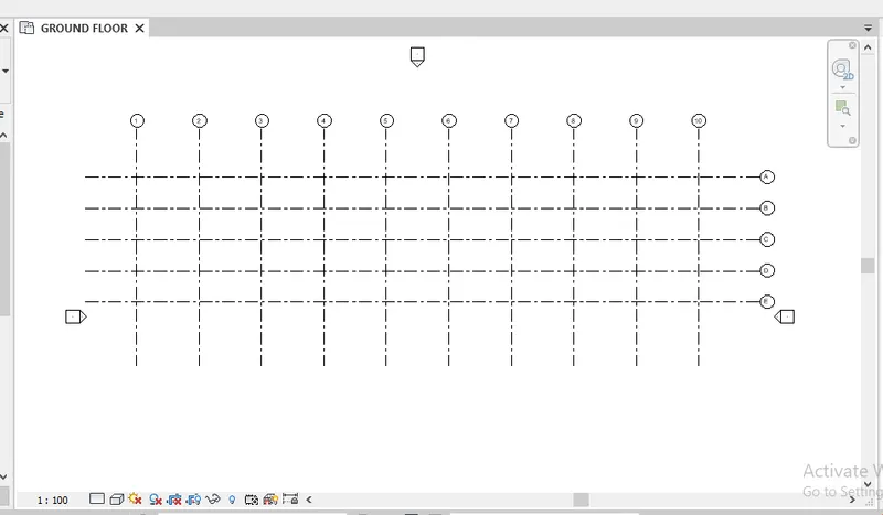
RESULT :
TO CREATED LEVELS
TO CREATED GRIDS
5) 3D modelling of residential unit – From looking at your house / or a place you aspire. Create a conceptual layout of the residential unit. You can measure using a tape or
you can access your residential plan to create a similar layout.
ans :
AIM : TO CREATE THE 3D MODELLING OF RESIDENTIAL
PROCEDURE :
STEP 1 : TO OPEN REVIT TOOL
OPEN REVIT SOFTWARE BY USING REVIT ICON
GO TO NEW
SCELET TEMPLATE FILE AS ARCHITECTURAL TEMPLATE
SCELET CREATE NEW AS PROJECT
FINALY CLICK ON OK
STEP 2 : PROJECT UNITS
GO TO MANAGE TAB
GO TO PROJECT UNITS ICON
OR
CLICK ON PROJECT UNITS COMMAND IS UN TYPE THE KEYBOARD
OPEN THE PROJECT UNITS POP UP
CHANGE THE UNITS ARE AS YOUR REQUIRED PROJECT UNITS / BASED ON YOUR PROJECT DOING
FINALY CLICK ON OK
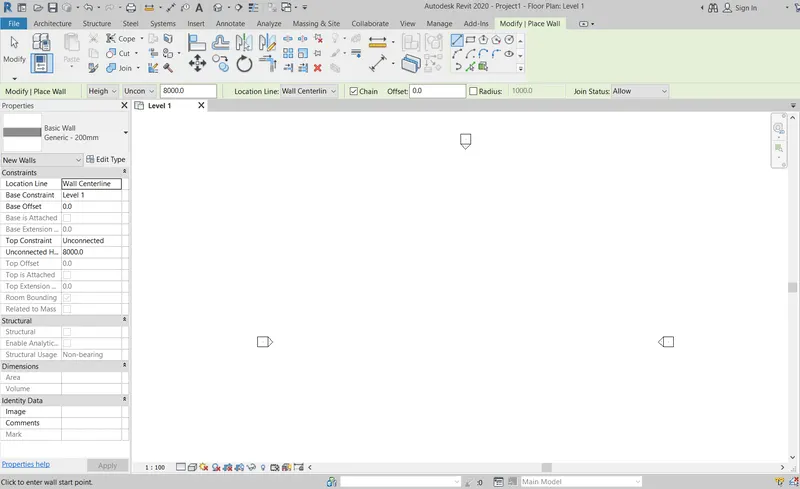
STEP 3 : TO CREATE LEVELS
TO CREATE LEVELS AS REQUIRED AS
GROUND FLOOR AT 0'
FIRST FLOOR AT 10'
SECOND FLOOR AT 20'
ROOF AT 30'
GO TO ANY ONE ELEVATIONS VIEWS
TO CHANGE THE LEVEL 1 AND LEVEL 2 HEGHIT FOR 10' AND AS WELL AS NAME AS LEVEL 1 IS GROUND FLOOR AND LEVEL 2 IS FIRST FLOOR
NEXT TO TAKE THE LEVEL OPTIONS
GO TO ARCHITECTURAL TAB
THEN GO TO DATUM
THEN TAKE LEVELS OPTIONS
OR
LEVELS OPTIONS KEYBOARD SHORT KUT IS LL PRESS
DRAW THE LEVELS AS YOUR REQUIRED AT
SECOND FLOOR AT 20'
ROOF AT 30'
AS WELL AS TO CHENGE THE NAME AS REQUIRED ABOVE NAMES
TO CREAED THE 3D MODELLING OF RESIDENTIAL
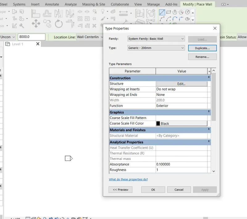
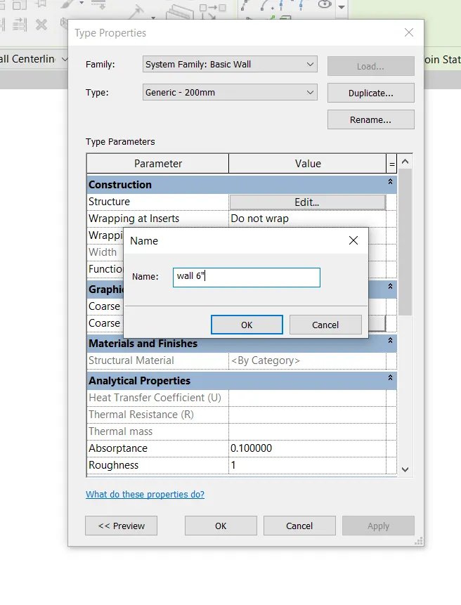
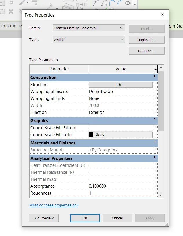
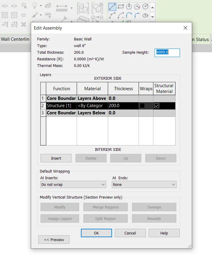
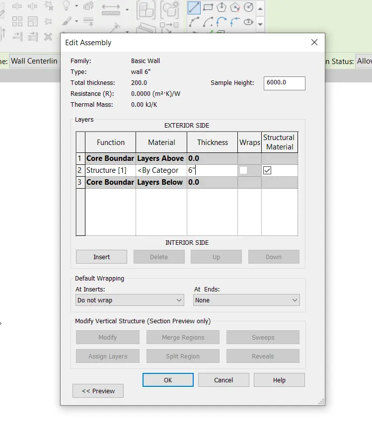
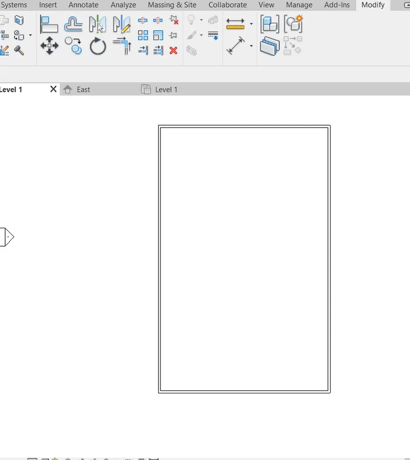
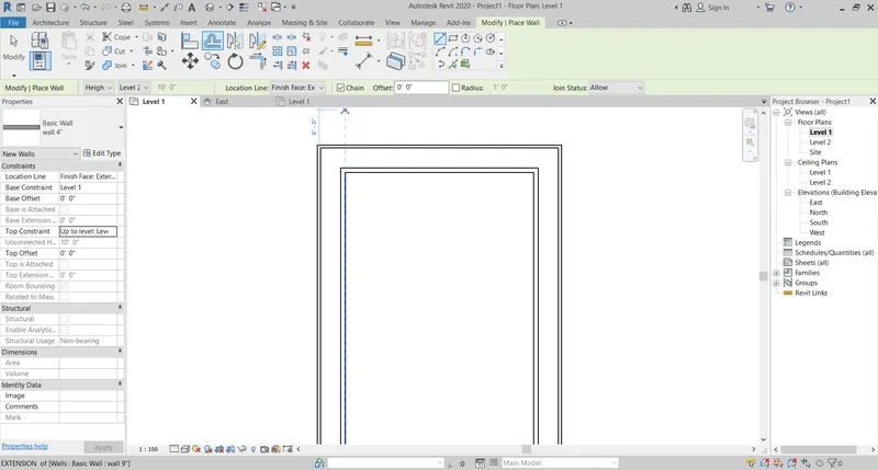
STEP 4 : TO CREAT THE COUMPUND WALL
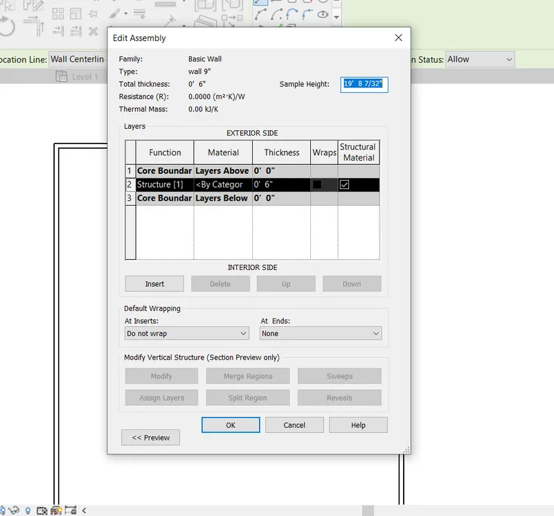
COUMPUND WALL THICK IS 6"
COUMPUND WALL HEGITH IS 7'
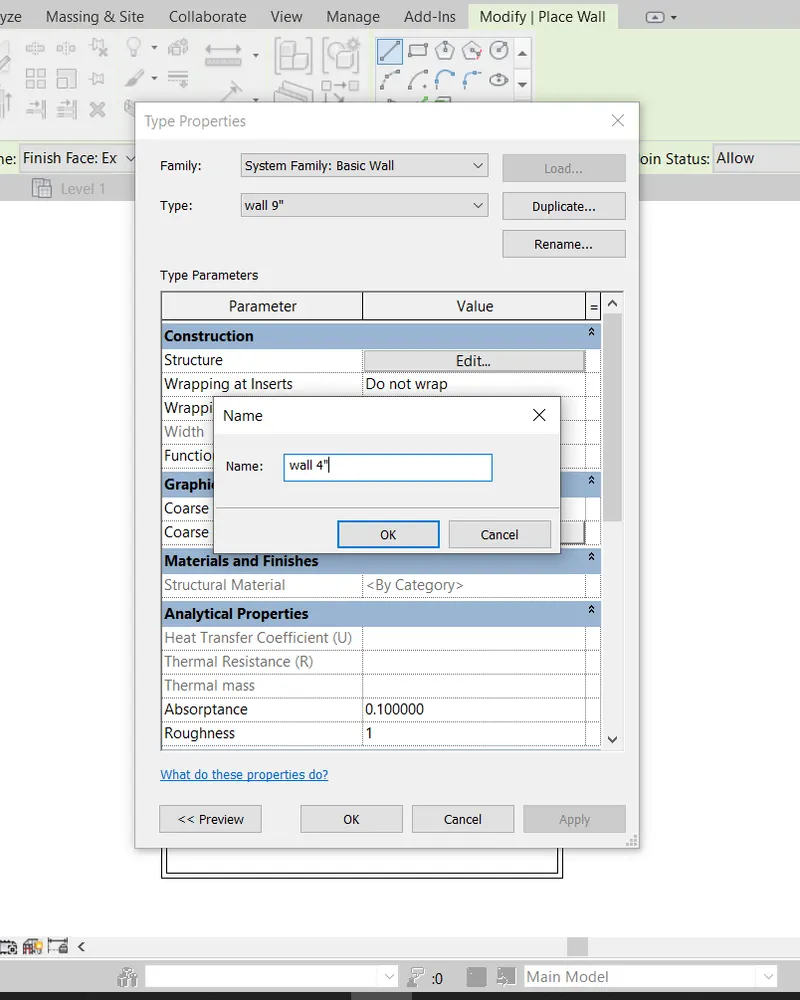
TO CREAT THE WALL FOR 6" WALL
BY USEING THE
GO TO TAKE THE WALL COUMMEND
GO TO EDIT TYPE
TEN DUPLIKE
THEN GIVE NAME
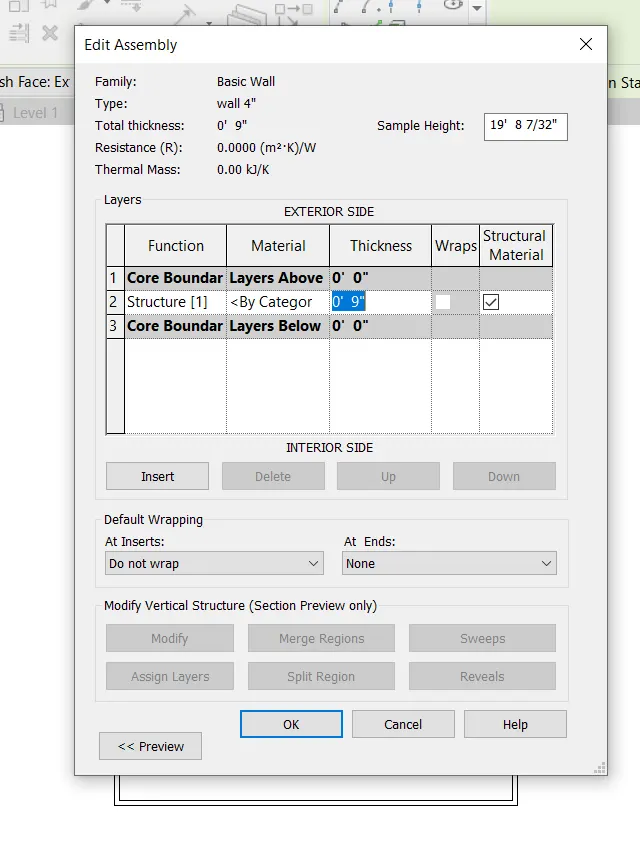
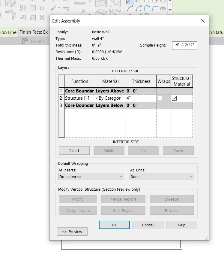
THEN GO TO EDIT
TEHEN GIVE THE REQUIRED DIMENITENS
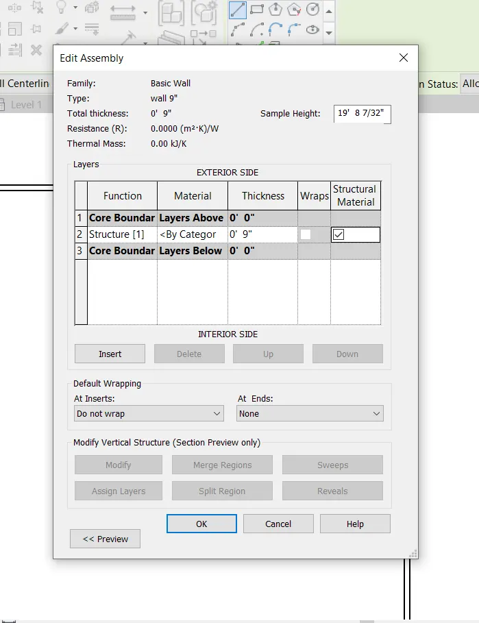
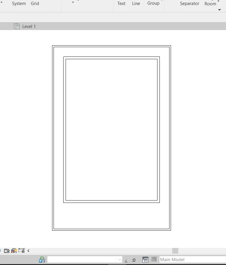
STEP 5 : TO CREAT THE OUTER WALL
OUTER WALL THICK IS 6"
OUTER WALL HEGITH IS 7'
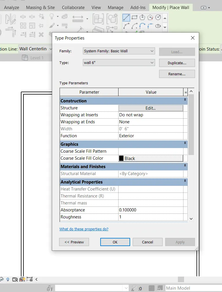
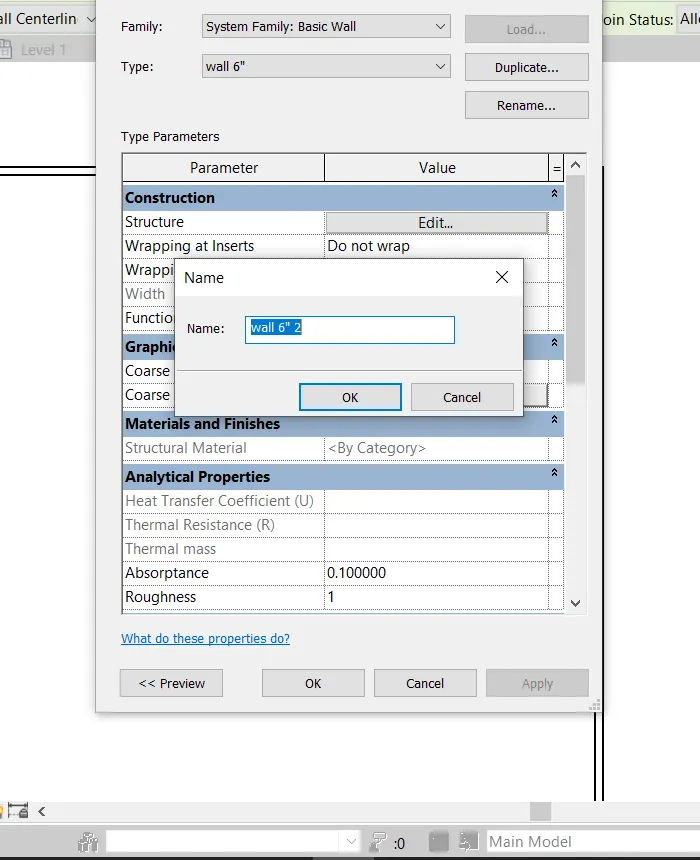
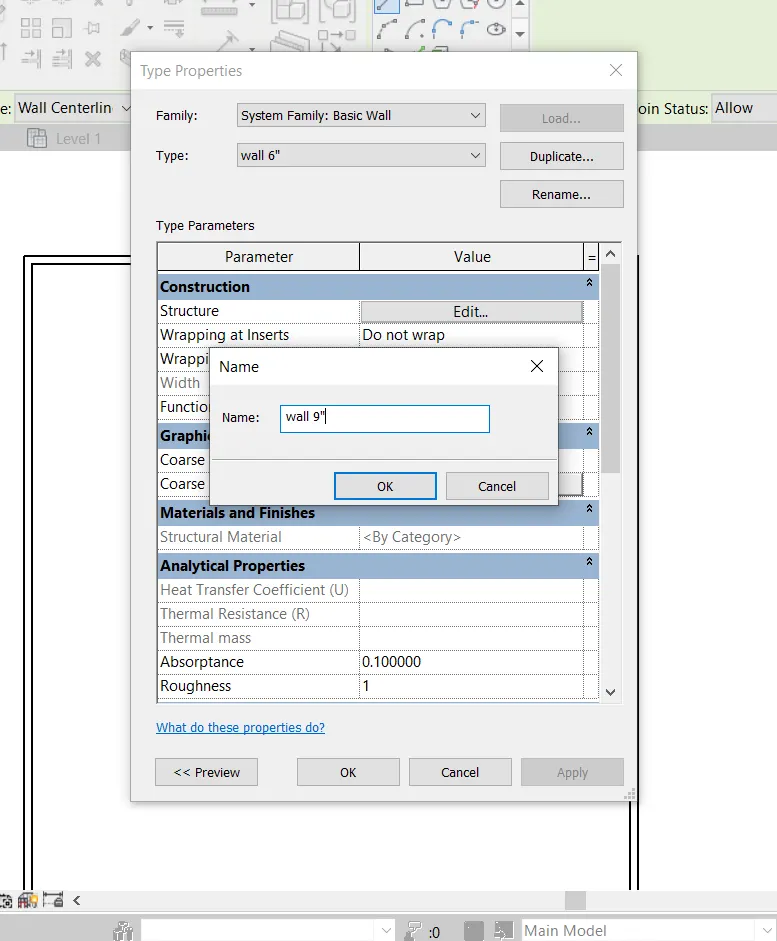
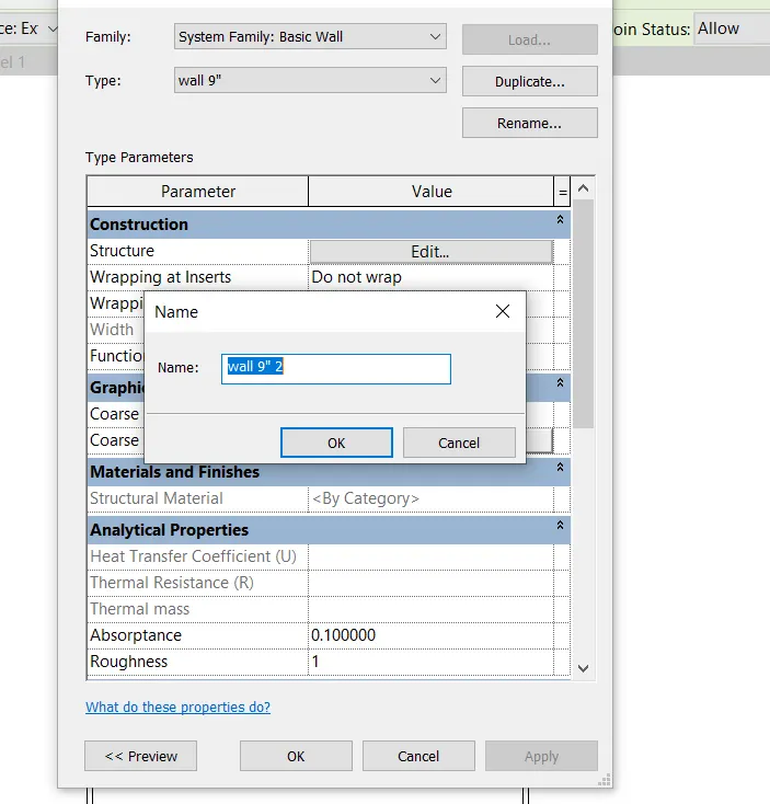
TO CREAT THE WALL FOR 9" WALL
BY USEING THE
GO TO TAKE THE WALL COUMMEND
GO TO EDIT TYPE
TEN DUPLIKE
THEN GIVE NAME
THEN GO TO EDIT
TEHEN GIVE THE REQUIRED DIMENITENS
FOOLR HEIGHT IS 10'
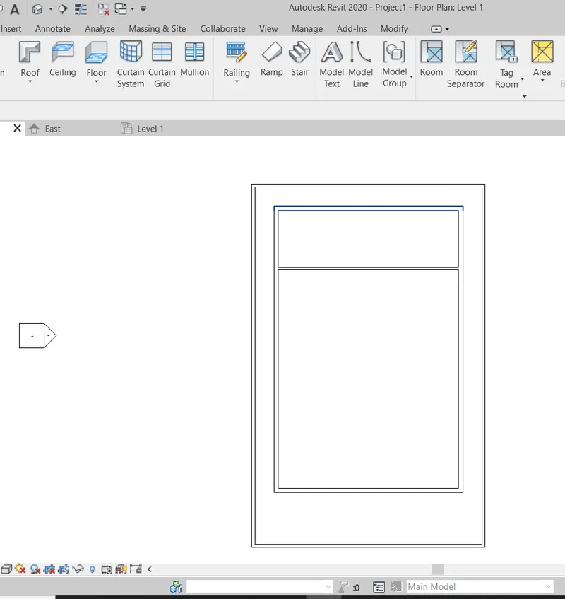
STEP 5 : TO CREATE THE INER WALL
INER WALL THICK IS 6"
INER WALL HEGITH IS 7'
TO CREAT THE WALL FOR 4.5" WALL
BY USEING THE
GO TO TAKE THE WALL COUMMEND
GO TO EDIT TYPE
TEN DUPLIKE
THEN GIVE NAME
THEN GO TO EDIT
THEN GIVE THE REQUIRED DIMENITENS
FOOLR HEIGHT IS 10'
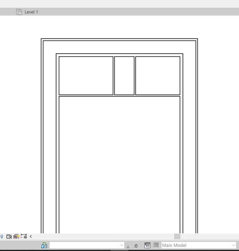
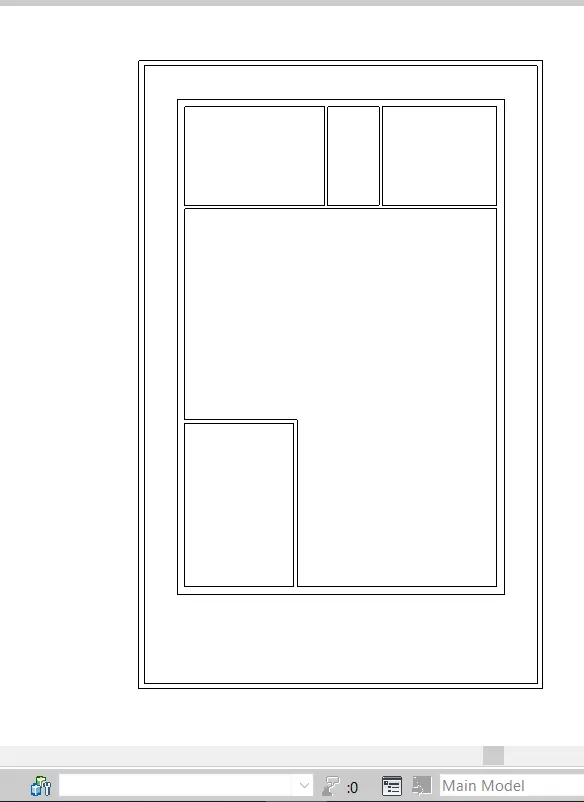
THEN TO CREAT THE ROOMS AS REQUIRED DIMENITENS
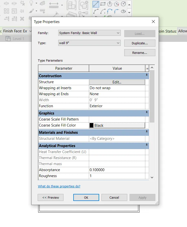
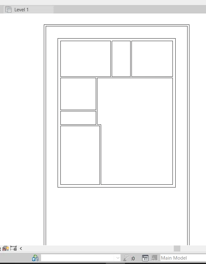
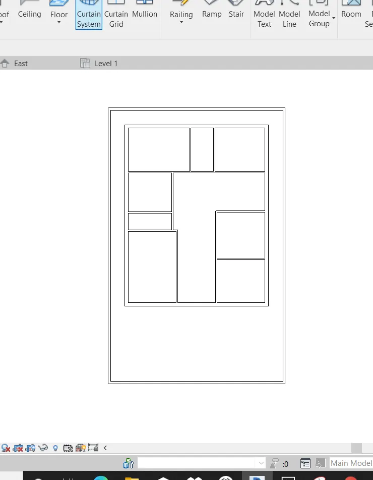
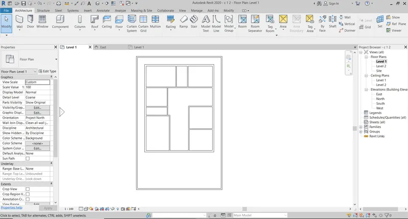
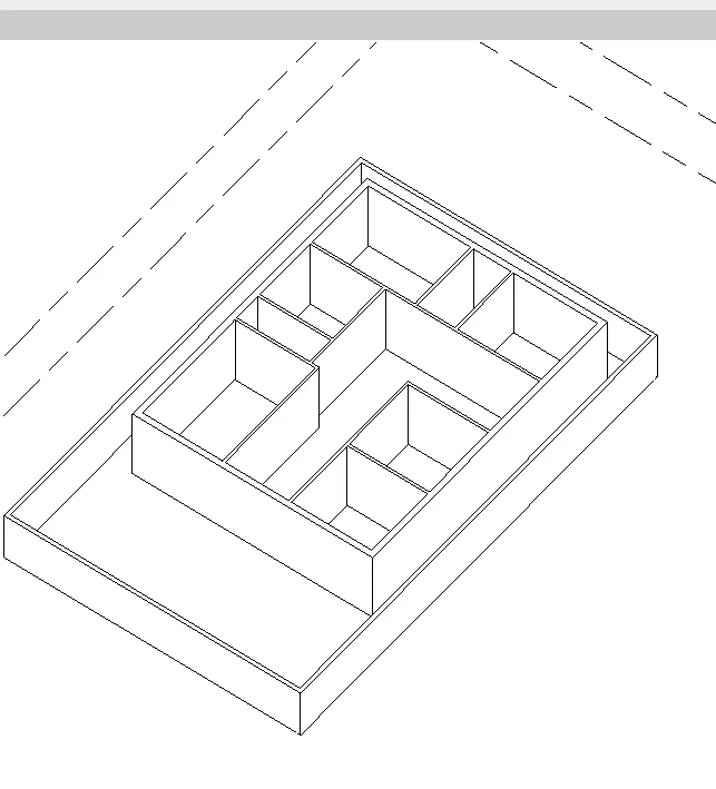
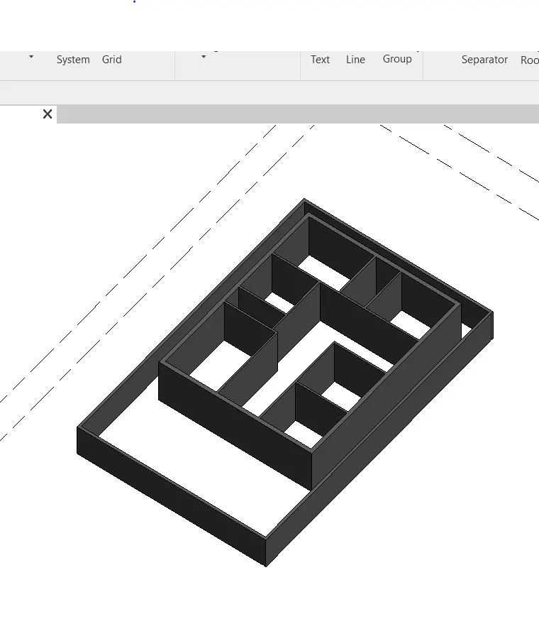
RESULT :
TO CREAED THE 3D MODELLING OF RESIDENTIAL
3D VIEW
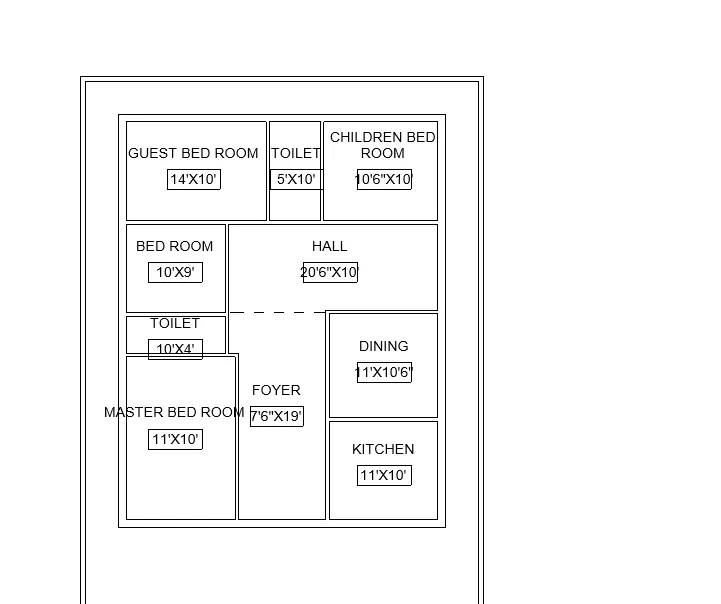
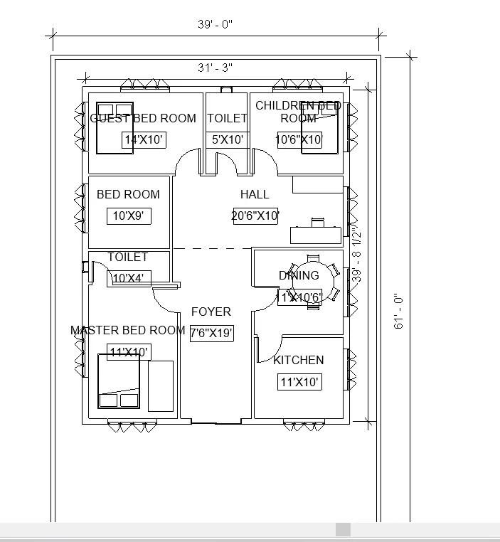
6) In the layout created draft the level of details you are planning to include – Dimensions of room, components you plan to add in the residential unit.
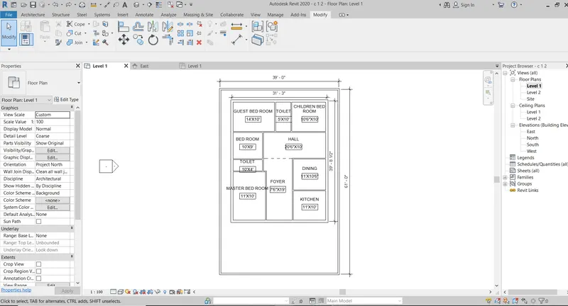
AIM : TO ADD THE DIMENSIONS OF ROOM, TO SET THE ROOM TAG, COMPONENTS IN MY PLAN
TO COUNTIUNED ON 5TH QUESTION
TO ADD THE DIMENSIONS OF ROOM, TO SET THE ROOM TAG, COMPONENTS IN MY PLAN
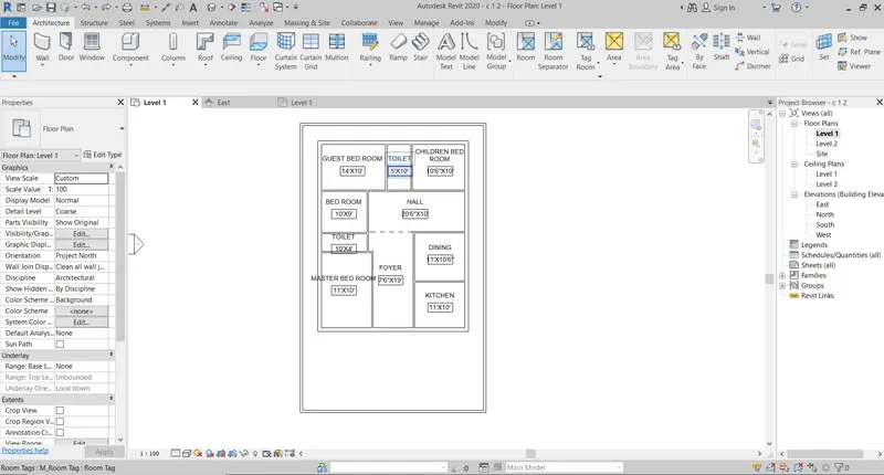
TO CREATED THE ROOM DIMENSION ARE ADDED THE USEING ROOM TAG OPTION
TO PLACE THE ROOM TAG
THEN EDIT THE ROOM TAG AD YOUR REQUIRED NAMES
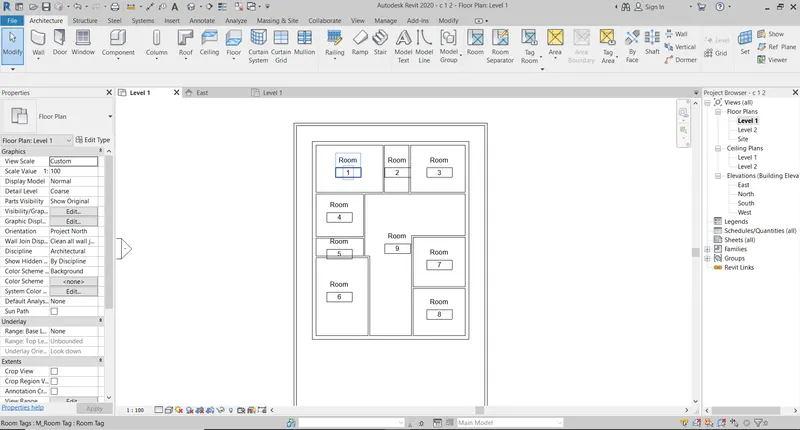
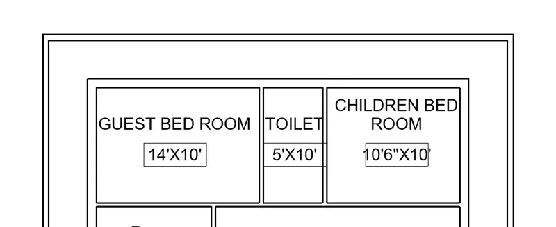
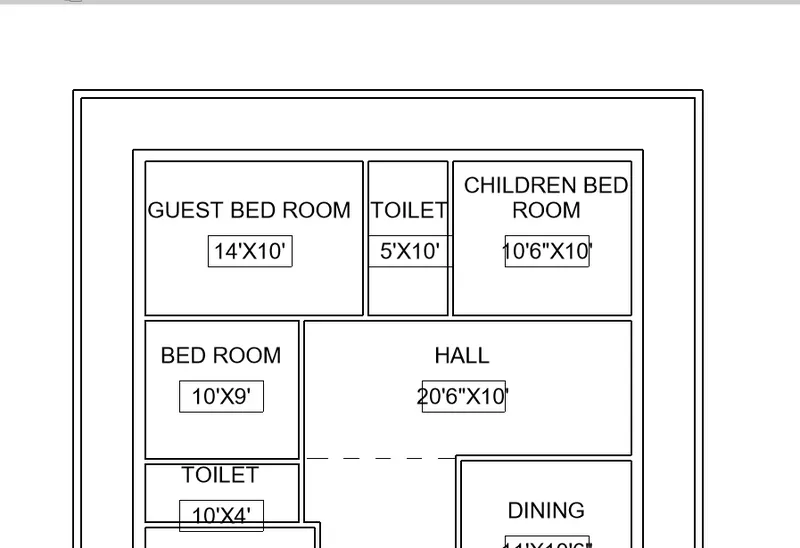
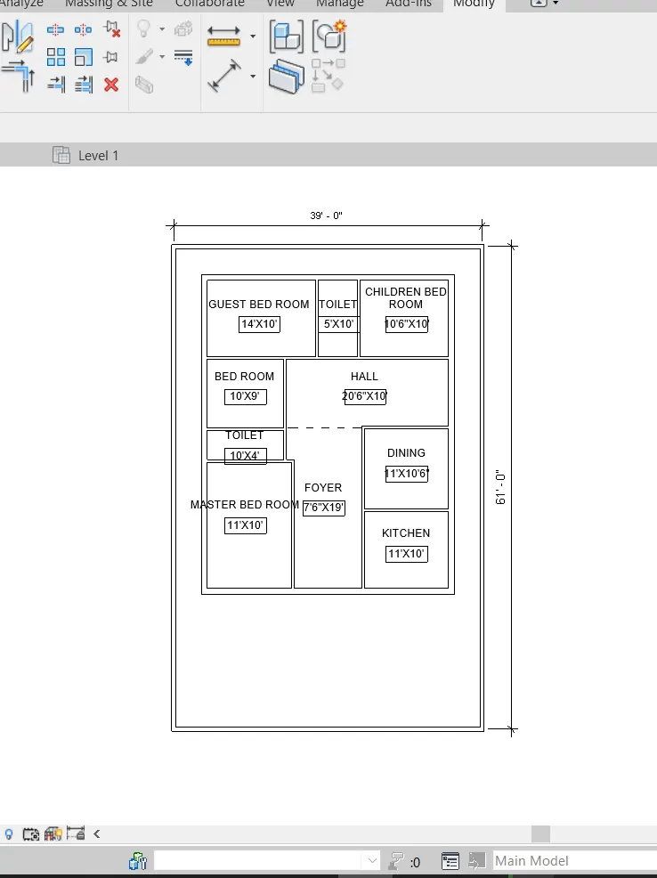
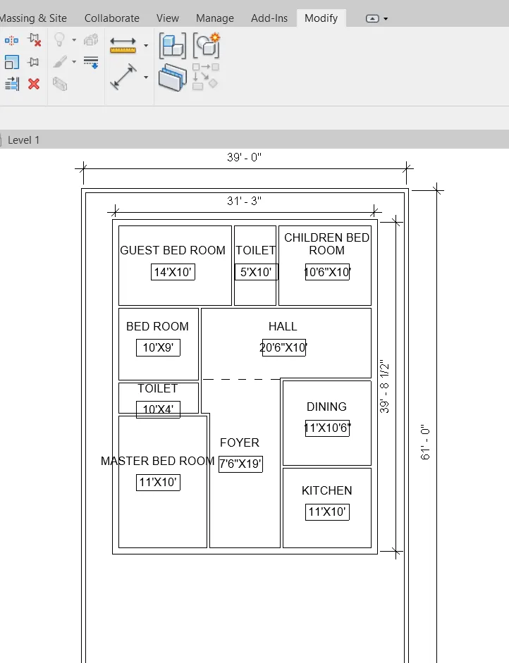
DIMENSION ARE ADD TO USED THE ALIGBNED DIMENSION
ALIGBNED DIMENSION SUTCUT IS AL PRESS IT
THEN TEKE THE ALIGBNED DIMENSION FOR REQUIRED DIMENSION
RESULT :
FANALY TO ADDED THE DIMENSIONS OF ROOM, TO SET THE ROOM TAG, COMPONENTS IN MY PLAN
7) Identify the residential model elements such as Door, Windows, Tables, Chair, Couch, Bed, Lamps from the library and insert them to the model . Save the project for use
for Assignment 3
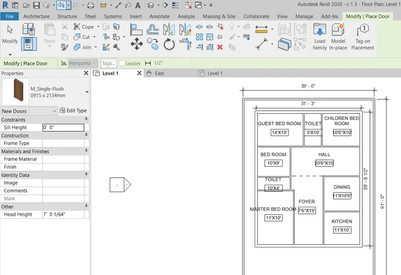
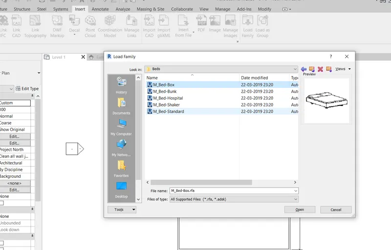
AIM : LOAD AS YOUR REQURIED FIMELES AS DOORS ,WINDOWS,TABLES,CHAIR,COUSH,BEDS,LAMPS FROM THE LIBRARY AND INSERT THEM THE MODEL.
TO COUNTIUNED ON 6TH QUESTION
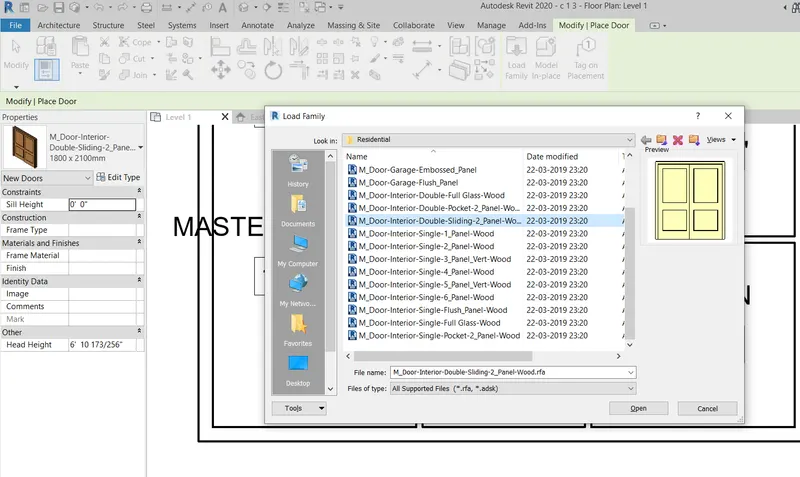
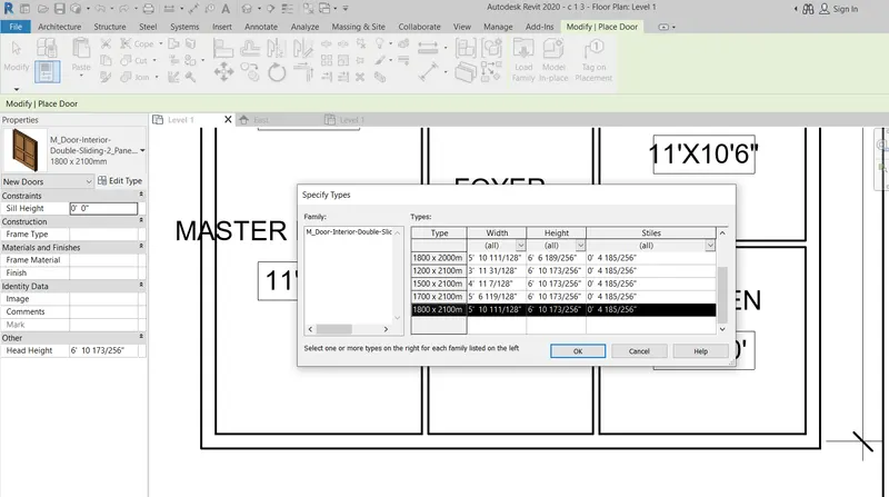
TO LOAD THE FAMILIES
GO TO INSERT TAB AS SHOWN BELOW
CLICK ON LOAD FAMILIES
FROM THE POP-UP BOX SELECT LABRARIES
GO TO INDIA
GO TO DOORS / WINDOWS / OR AS YOUR REQUIRED FAMILIES
GO TO RESIDENTIAL TYPE
CLICK ON DOOR TYPE
FINALY CLICK ON OPEN
PLACE THE DOORS OR ANY FAMILIES ARE AS YOUR REQUIRED AREA
OR
PROJECT BROWSER
FAMILIES ARE ALSO BE ADDED FROM THE PROJECT BROWSER ALSO
GO TO PROJECT BROWSER
IN GO TO FAMILIES [ + ]
GO TO DOORS / WINDOWS / OR AS YOUR REQUIRED FAMILIES
GO TO RESIDENTIAL TYPE
CLICK ON DOOR TYPE
CLICK ON DRAG THE REQUIRED FAMILIES
PLACE THE DOORS OR ANY FAMILIES ARE AS YOUR REQUIRED AREA
LOAD AS YOUR REQURIED FIMELES AS DOORS ,WINDOWS,TABLES,CHAIR,COUSH,BEDS,LAMPS FROM THE LIBRARY AND INSERT THEM THE MODEL.
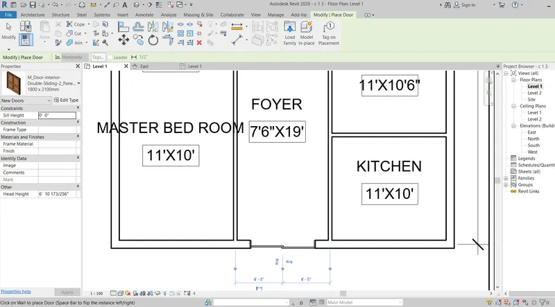
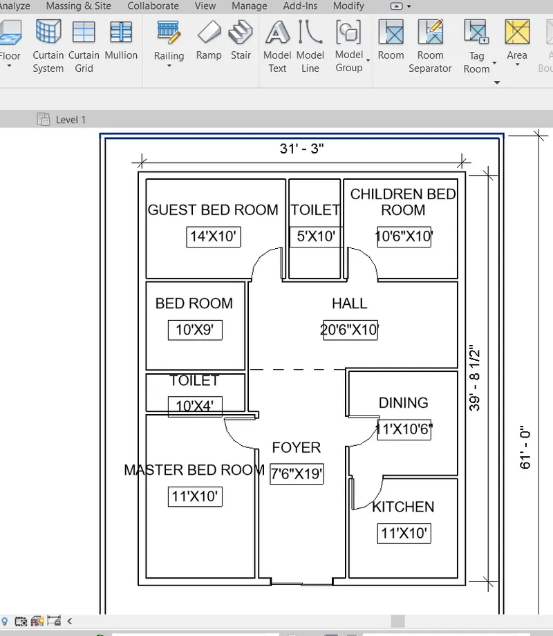
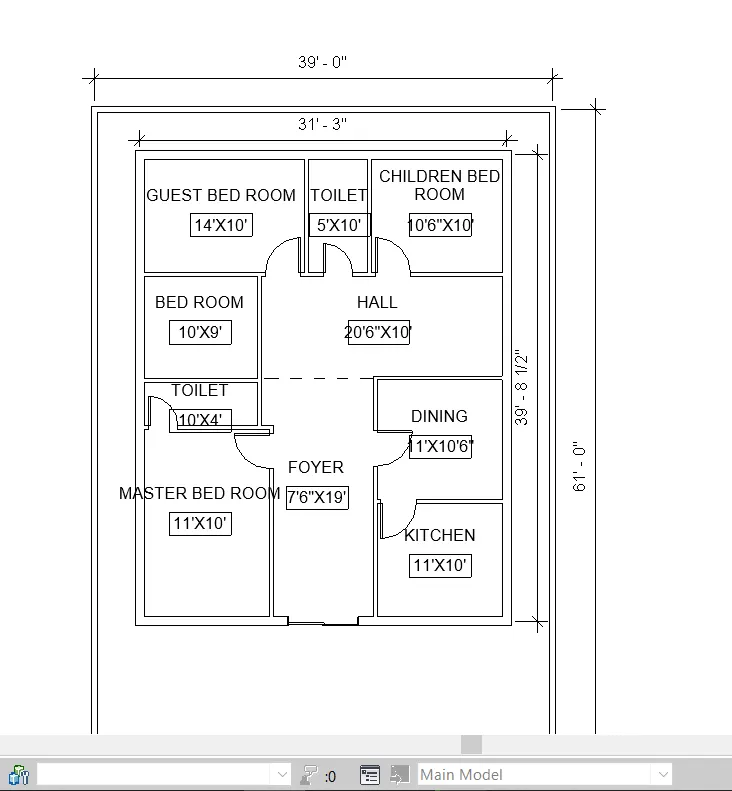
TO LOAD THE FAMILIES
GO TO INSERT TAB AS SHOWN BELOW
CLICK ON LOAD FAMILIES
FROM THE POP-UP BOX SELECT LABRARIES
GO TO INDIA
GO TO DOORS / WINDOWS / OR AS YOUR REQUIRED FAMILIES
GO TO RESIDENTIAL TYPE
CLICK ON DOOR TYPE
FINALY CLICK ON OPEN
PLACE THE WINDOWS OR ANY FAMILIES ARE AS YOUR REQUIRED AREA
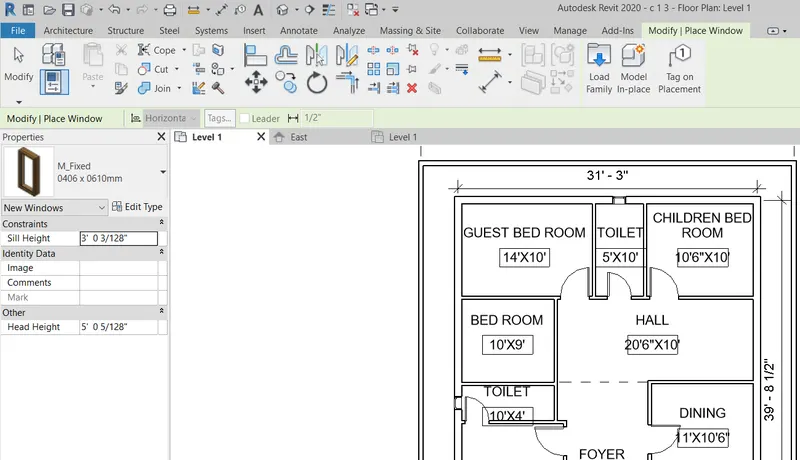
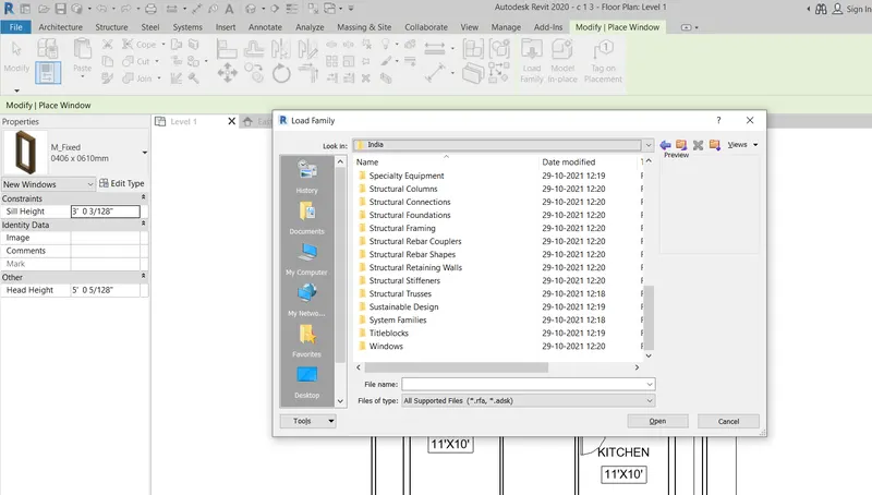
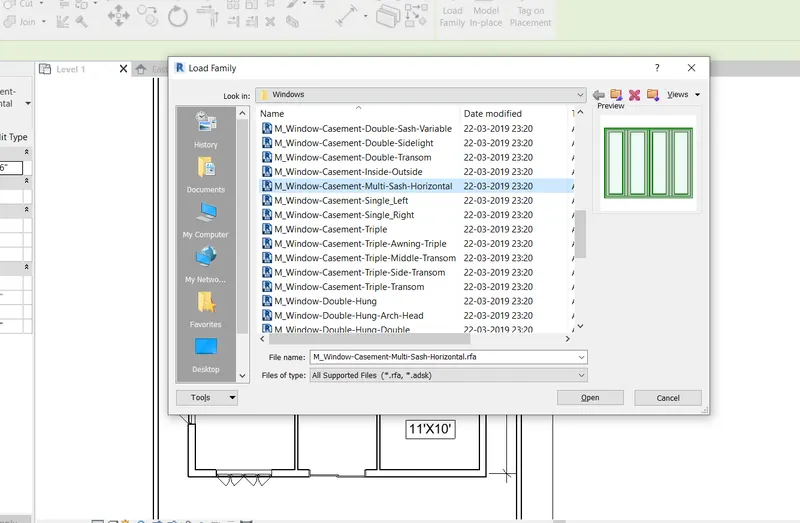
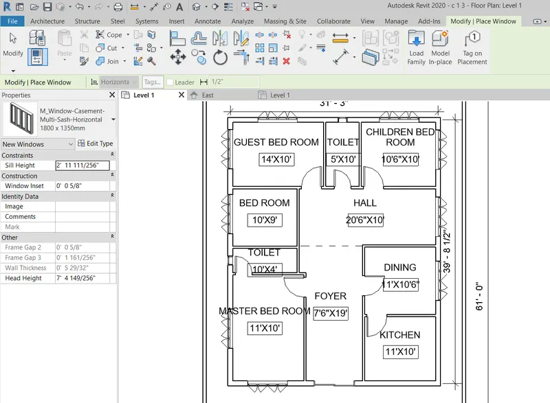
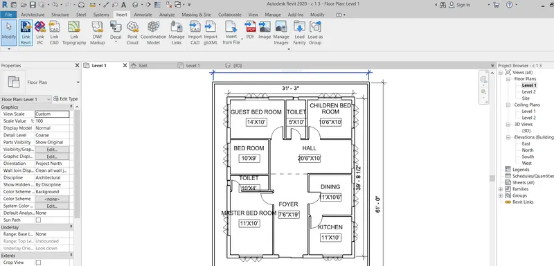
TO LOAD THE FAMILIES
GO TO INSERT TAB AS SHOWN BELOW
CLICK ON LOAD FAMILIES
FROM THE POP-UP BOX SELECT LABRARIES
GO TO INDIA
GO TO DOORS / WINDOWS / OR AS YOUR REQUIRED FAMILIES
GO TO RESIDENTIAL TYPE
CLICK ON DOOR TYPE
FINALY CLICK ON OPEN
PLACE THE WINDOWS OR ANY FAMILIES ARE AS YOUR REQUIRED AREA
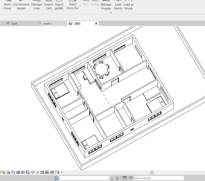
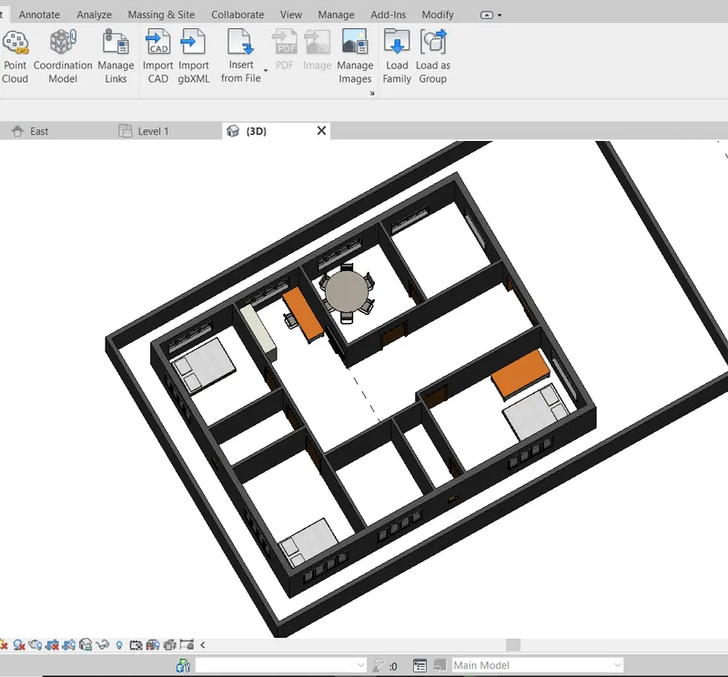
RESULT :
LOADED AS YOUR REQURIED FIMELES AS DOORS ,WINDOWS,TABLES,CHAIR,COUSH,BEDS,LAMPS FROM THE LIBRARY AND INSERT THEM THE MODEL.