Drafting of various geometries using Chamfer, Fillet tool in AutoCad
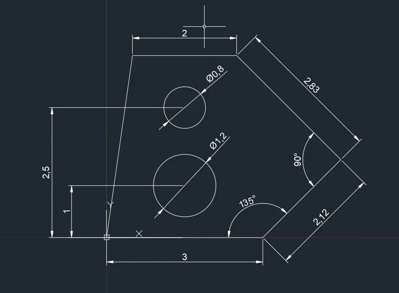
QUESTION : 1
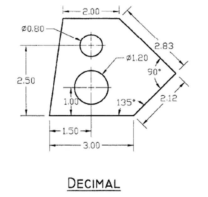
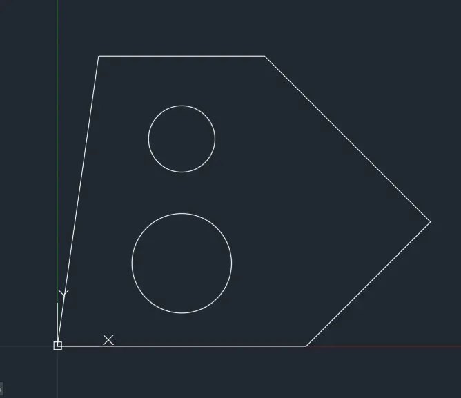
AIM : TO DRAW THE ABOVE FIGUREBY USING AUTOCAD
PROCEDURE :
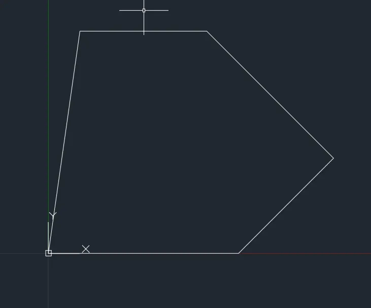
LINE Command: L
Specify first point: 0,0
Specify next point or [Undo]: @3<0
Specify next point or [eXit/Undo]: @2.12<45
Specify next point or [Close/eXit/Undo]: @2.83<135
Specify next point or [Close/eXit/Undo]: @2<180
Specify next point or [Close/eXit/Undo]: C
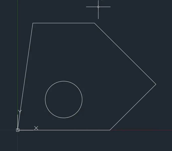
CIRCLE Command: C
Specify center point for circle or [3P/2P/Ttr (tan tan radius)]: 1.5,1
Specify radius of circle or [Diameter] <1.5000>: D Specify diameter of circle <3.0000>: 1.2
CIRCLE Command: C
Specify center point for circle or [3P/2P/Ttr (tan tan radius)]: 1.5,2.5
Specify radius of circle or [Diameter] <0.6000>: D Specify diameter of circle <1.2000>: 0.8
RESULTS :
- ALL DIMENSIONS ARE IN METERS ( m )
QUESTION : 2
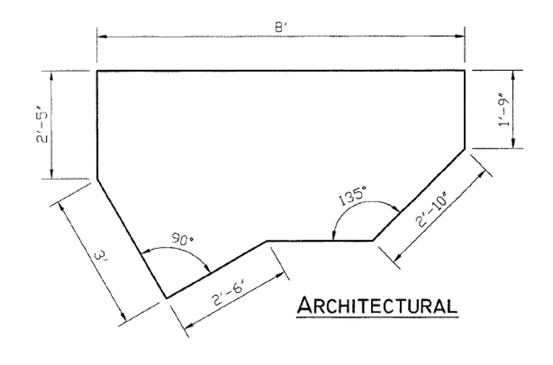
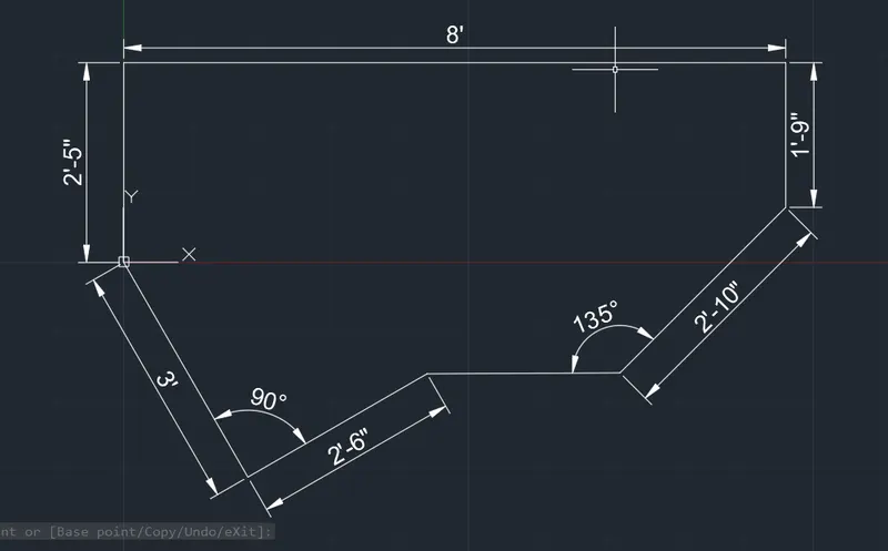
AIM : TO DRAW THE ABOVE FIGUREBY USING AUTOCAD
PROCEDURE :
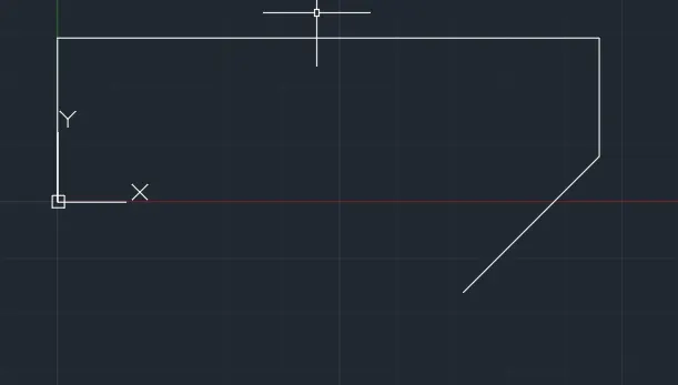
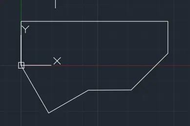
LINE Command: L
Specify first point: 0,0
Specify next point or [Undo]: @0,2'5"
Specify next point or [eXit/Undo]: @8',0
Specify next point or [Close/eXit/Undo]: @0,-1'9"
Specify next point or [Close/eXit/Undo]: @2'10"<225
Specify next point or [Close/eXit/Undo]:
LINE Command: L
Specify first point: 0,0
Specify next point or [Undo]: @3'<300
Specify next point or [eXit/Undo]: @2'6"<30
Specify next point or [Close/eXit/Undo]: mouse click
Specify next point or [Close/eXit/Undo]:
RESULTS :
- ALL DIMENSIONS ARE IN FEETS AND INCHES
- INCLUDED ANGLES ARE CALCULATED MANUALLY
QUESTION : 3
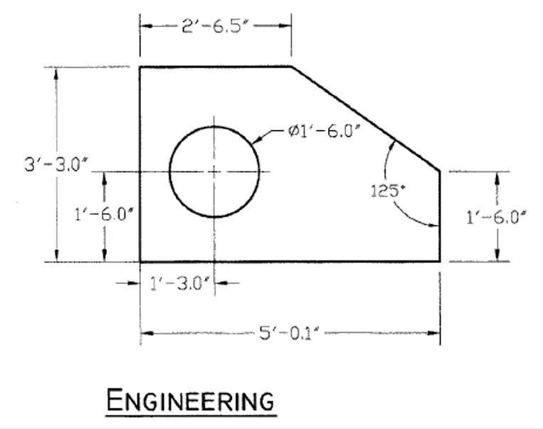
AIM : TO DRAW THE ABOVE FIGUREBY USING AUTOCAD
PROCEDURE :
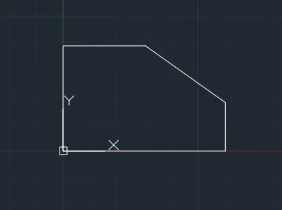
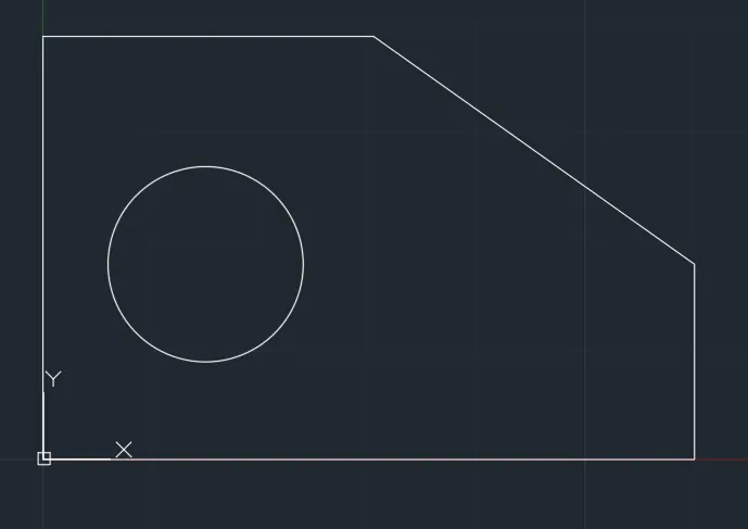
LINE Command: L
Specify first point: 5'0.1",1'6"
Specify next point or [Undo]: @1'6"<270
Specify next point or [eXit/Undo]: @5'0.1"<180
Specify next point or [Close/eXit/Undo]: @3'3"<90
Specify next point or [Close/eXit/Undo]: @2'6.5"<0
Specify next point or [Close/eXit/Undo]: C
CIRCLE Command: C
Specify center point for circle or [3P/2P/Ttr (tan tan radius)]: 1'3",1'6"
Specify radius of circle or [Diameter] <20'-10.00">: D
Specify diameter of circle <41'-8.00">: 1'6"
OR
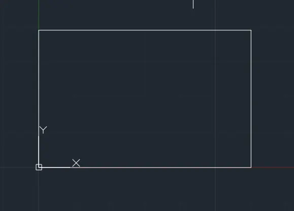
RECTANGLE Command: REC
Specify first corner point or [Chamfer/Elevation/Fillet/Thickness/Width]: 0,0
Specify other corner point or [Area/Dimensions/Rotation]: @5'0.1",3'3"
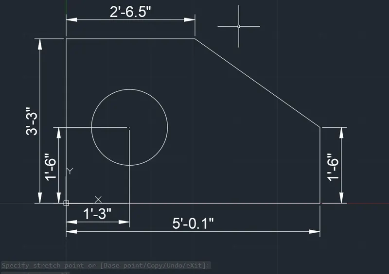
Command: CHA CHAMFER
(TRIM mode) Current chamfer Dist1 = 0'-0.00", Dist2 = 0'-0.00"
Select first line or [Undo/Polyline/Distance/Angle/Trim/mEthod/Multiple]: D
Specify first chamfer distance <0'-0.00">: 2'5.6"
Specify second chamfer distance <2'-5.60">: 1'9"
Select first line or [Undo/Polyline/Distance/Angle/Trim/mEthod/Multiple]:
Select second line or shift-select to apply corner or [Distance/Angle/Method]:
CIRCLE Command: C
Specify center point for circle or [3P/2P/Ttr (tan tan radius)]: 1'3",1'6"
Specify radius of circle or [Diameter] <20'-10.00">: D
Specify diameter of circle <41'-8.00">: 1'6"
RESULTS :
- ALL DIMENSIONS ARE IN FEETS AND INCHES
- INCLUDED ANGLES ARE CALCULATED MANUALLY
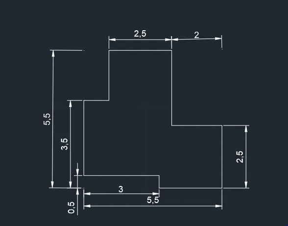
QUESTION : 4
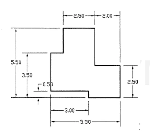
AIM : TO DRAW THE ABOVE FIGUREBY USING AUTOCAD
PROCEDURE :
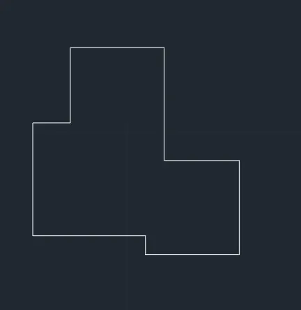
LINE Command: L
Specify first point: 0,0
Specify next point or [Undo]: @3,0
Specify next point or [eXit/Undo]: @0,-0.5
Specify next point or [Close/eXit/Undo]: @2.5,0
Specify next point or [Close/eXit/Undo]: @0,2.5
Specify next point or [Close/eXit/Undo]: @-2,0
Specify next point or [Close/eXit/Undo]: @0,3
Specify next point or [Close/eXit/Undo]: @-2.5,0
Specify next point or [Close/eXit/Undo]: @0,-2
Specify next point or [Close/eXit/Undo]: @-1,0
Specify next point or [Close/eXit/Undo]: @0,-3
Specify next point or [Close/eXit/Undo]:
RESULTS :
- ALL DIMENSIONS ARE IN METERS ( m )
QUESTION : 5
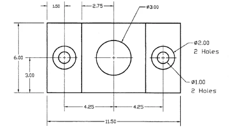
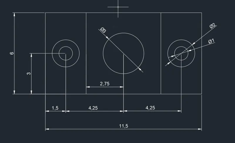
AIM : TO DRAW THE ABOVE FIGUREBY USING AUTOCAD
PROCEDURE :
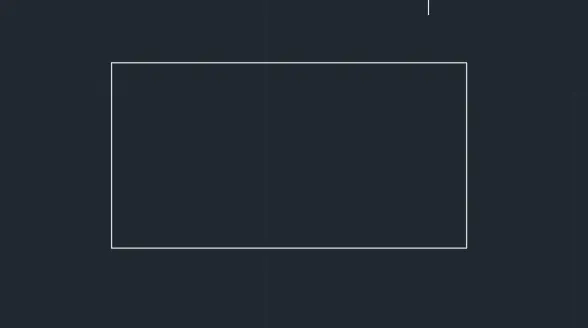
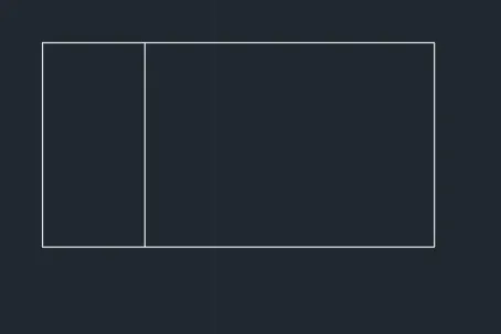
RECTANGLE Command: REC
Specify first corner point or [Chamfer/Elevation/Fillet/Thickness/Width]: 5,5
Specify other corner point or [Area/Dimensions/Rotation]: d
Specify length for rectangles <10.0000>: 11.5
Specify width for rectangles <10.0000>: 6
Specify other corner point or [Area/Dimensions/Rotation]:
LINE Command: L
Specify first point: 8,5
Specify next point or [Undo]: 8,11
Specify next point or [eXit/Undo]:
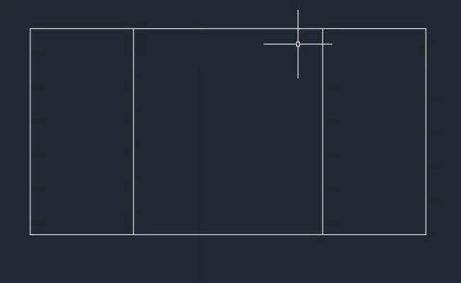
LINE Command: L
Specify first point: 13.5,5
Specify next point or [Undo]: 13.5,11
Specify next point or [eXit/Undo]:
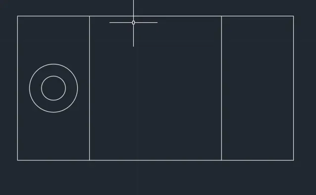
CIRCLE Command: C
Specify center point for circle or [3P/2P/Ttr (tan tan radius)]: 6.5,8
Specify radius of circle or [Diameter]: d Specify diameter of circle: 1
CIRCLE Command: C
Specify center point for circle or [3P/2P/Ttr (tan tan radius)]: 6.5,8
Specify radius of circle or [Diameter] <0.5000>: d Specify diameter of circle <1.0000>: 2
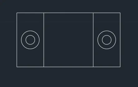
CIRCLE Command: C
Specify center point for circle or [3P/2P/Ttr (tan tan radius)]: 15,8
Specify radius of circle or [Diameter] <1.0000>: d Specify diameter of circle <2.0000>: 1
CIRCLE Command: C
Specify center point for circle or [3P/2P/Ttr (tan tan radius)]: 15,8
Specify radius of circle or [Diameter] <0.5000>: d Specify diameter of circle <1.0000>: 2
CIRCLE Command: C
Specify center point for circle or [3P/2P/Ttr (tan tan radius)]: 10.75,8
Specify radius of circle or [Diameter] <1.0000>: d Specify diameter of circle <2.0000>: 3
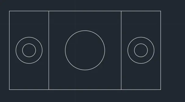
RESULTS :
- ALL DIMENSIONS ARE IN METERS ( m )
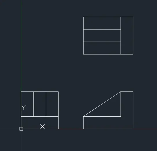
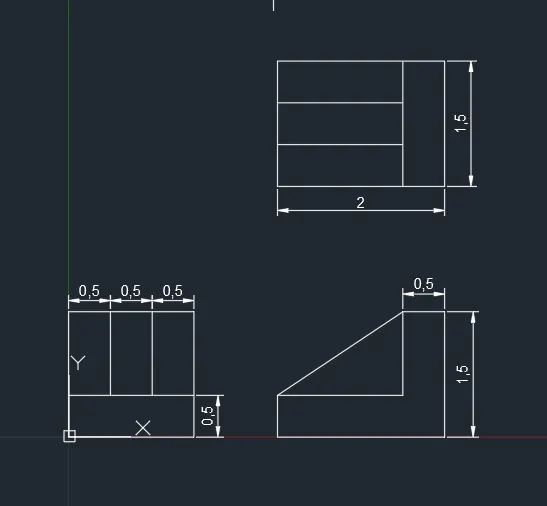
QUESTION : 6
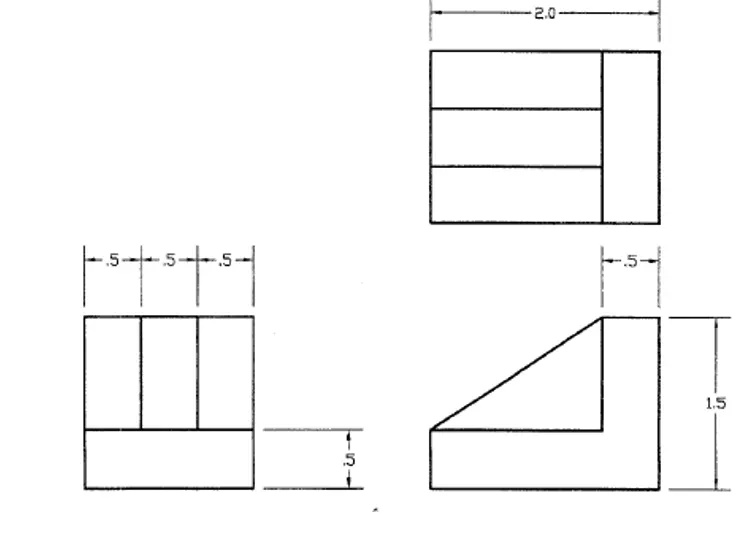
AIM : TO DRAW THE ABOVE FIGUREBY USING AUTOCAD
PROCEDURE :
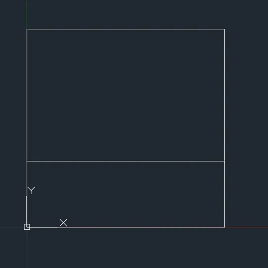
LINE Command: L
Specify first point: 0,0
Specify next point or [Undo]: 1.5,0
Specify next point or [eXit/Undo]: 1.5,1.5
Specify next point or [Close/eXit/Undo]: 0,1.5
Specify next point or [Close/eXit/Undo]: C
LINE Command: L
Specify first point: 0,0.5
Specify next point or [Undo]: 1.5,0.5
Specify next point or [eXit/Undo]:
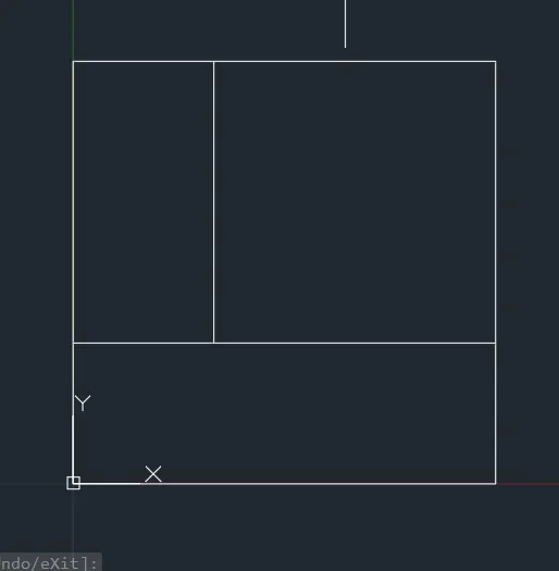
LINE Command: L
Specify first point: 0.5,0.5
Specify next point or [Undo]: 0.5,1.5
Specify next point or [eXit/Undo]:
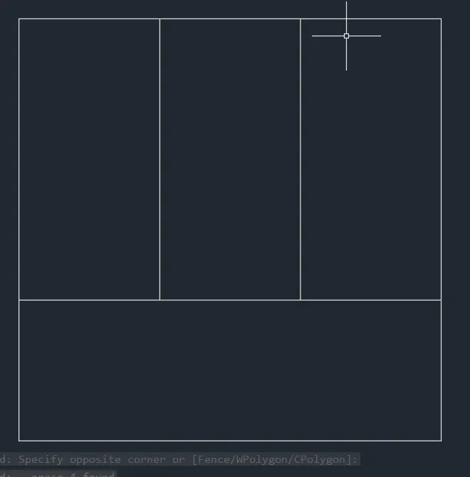
LINE Command: L
Specify first point: 1,0.5
Specify next point or [Undo]: 1,1.5
Specify next point or [eXit/Undo]:
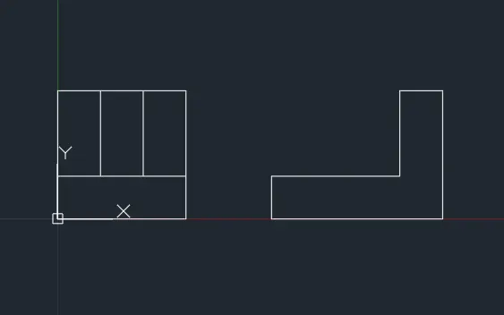
LINE Command: L
Specify first point: 2.5,0
Specify next point or [Undo]: 4.5,0
Specify next point or [eXit/Undo]: 4.5,1.5
Specify next point or [Close/eXit/Undo]: 4,1.5
Specify next point or [Close/eXit/Undo]: 4,0.5
Specify next point or [Close/eXit/Undo]: 2.5,0.5
Specify next point or [Close/eXit/Undo]: C
LINE Command: L
Specify first point: 2.5,0.5
Specify next point or [Undo]: 4,1.5
Specify next point or [eXit/Undo]:
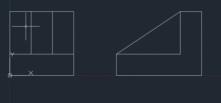
LINE Command: L
Specify first point: 2.5,3
Specify next point or [Undo]: 4.5,3
Specify next point or [eXit/Undo]: 4.5,4.5
Specify next point or [Close/eXit/Undo]: 2.5,4.5
Specify next point or [Close/eXit/Undo]: C
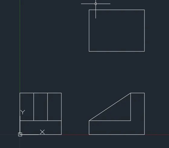
LINE Command: L
Specify first point: 4,3
Specify next point or [Undo]: 4,4.5
Specify next point or [eXit/Undo]:
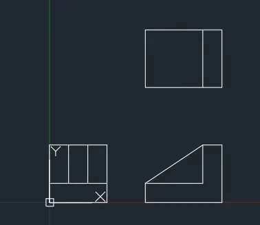
LINE Command: L
Specify first point: 2.5,3.5
Specify next point or [Undo]: 4,3.5
Specify next point or [eXit/Undo]:
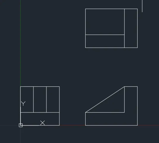
LINE Command: L
Specify first point: 2.5,4
Specify next point or [Undo]: 4,4
Specify next point or [eXit/Undo]:
RESULTS :
- ALL DIMENSIONS ARE IN METERS ( m )
QUESTION : 7
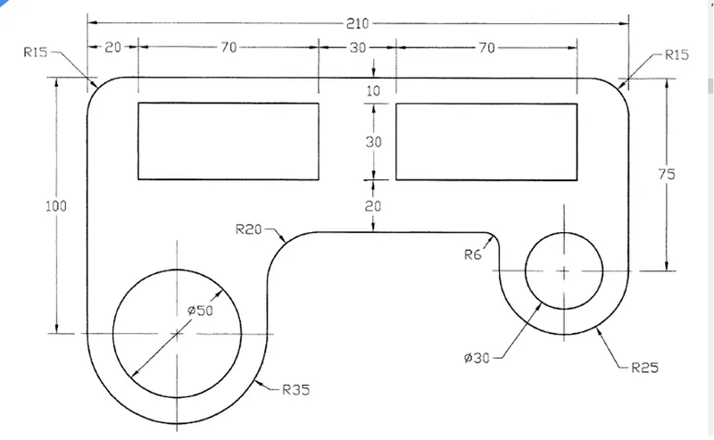
AIM : TO DRAW THE ABOVE FIGUREBY USING AUTOCAD
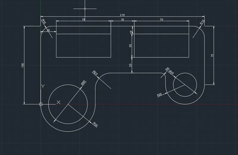
PROCEDURE :
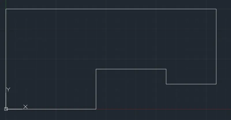
LINE Command: L
Specify first point: 0,0
Specify next point or [Undo]: 0,100
Specify next point or [eXit/Undo]: 210,100
Specify next point or [Close/eXit/Undo]: 210,25
Specify next point or [Close/eXit/Undo]: 160,25
Specify next point or [Close/eXit/Undo]: 160,40
Specify next point or [Close/eXit/Undo]: 70,40
Specify next point or [Close/eXit/Undo]: 70,0
Specify next point or [Close/eXit/Undo]: C
CIRCLE Command: C
Specify center point for circle or [3P/2P/Ttr (tan tan radius)]: 35,0
Specify radius of circle or [Diameter] <35.0000>: 35
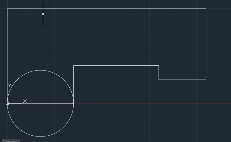
CIRCLE Command: C
Specify center point for circle or [3P/2P/Ttr (tan tan radius)]: 35,0
Specify radius of circle or [Diameter] <35.0000>: D Specify diameter of circle <70.0000>: 50
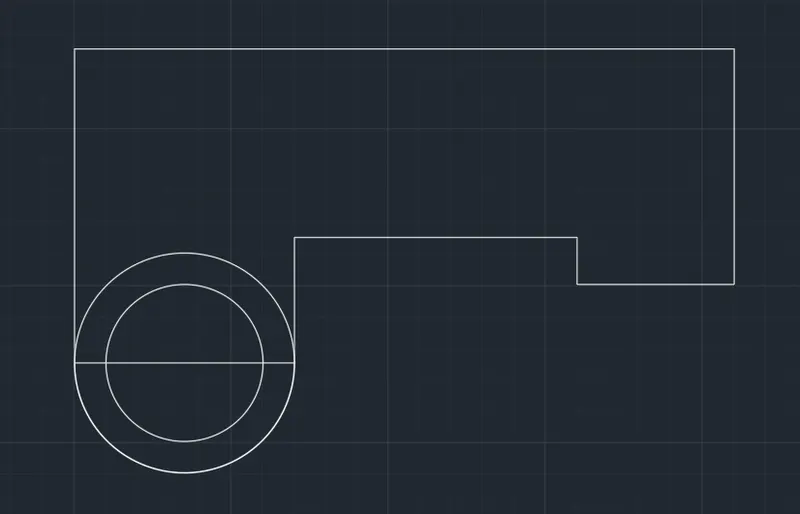
Command: TR TRIM
Current settings: Projection=UCS, Edge=None
Select cutting edges ...
Select objects or <select all>:
Select object to trim or shift-select to extend or [Fence/Crossing/Project/Edge/eRase]:
Select object to trim or shift-select to extend or [Fence/Crossing/Project/Edge/eRase/Undo]:
Select object to trim or shift-select to extend or [Fence/Crossing/Project/Edge/eRase/Undo]: *Cancel*
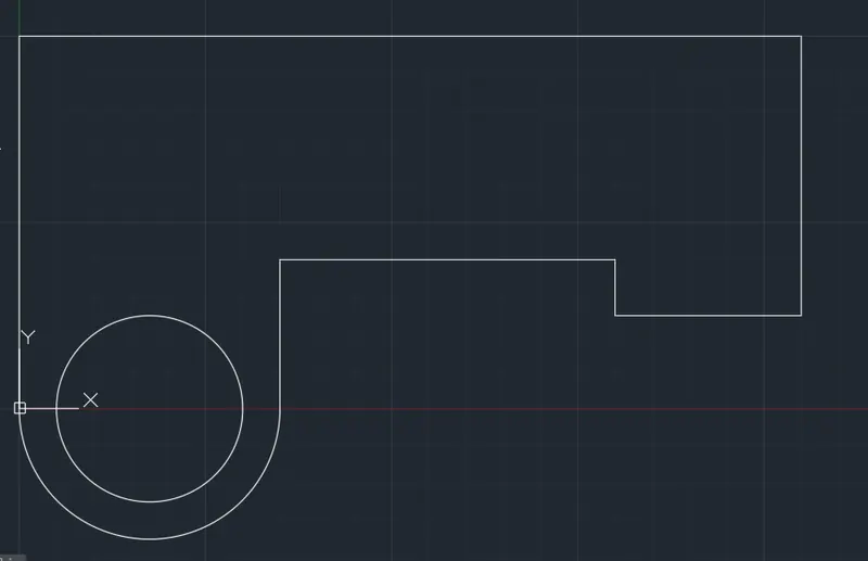
CIRCLE Command: C
Specify center point for circle or [3P/2P/Ttr (tan tan radius)]: 185,25
Specify radius of circle or [Diameter] <25.0000>: 25
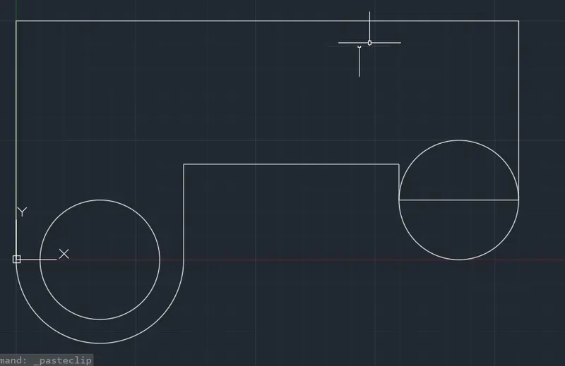
CIRCLE Command: C
Specify center point for circle or [3P/2P/Ttr (tan tan radius)]: 185,25
Specify radius of circle or [Diameter] <25.0000>: D Specify diameter of circle <50.0000>: 30
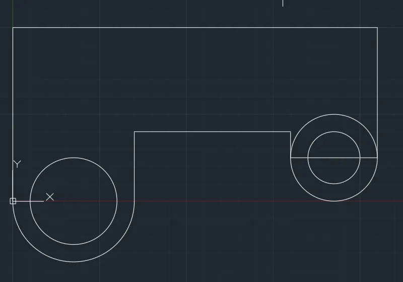
Command: TR TRIM
Current settings: Projection=UCS, Edge=None
Select cutting edges ...
Select objects or <select all>:
Select object to trim or shift-select to extend or [Fence/Crossing/Project/Edge/eRase]:
Select object to trim or shift-select to extend or [Fence/Crossing/Project/Edge/eRase/Undo]:
Select object to trim or shift-select to extend or [Fence/Crossing/Project/Edge/eRase/Undo]: *Cancel*
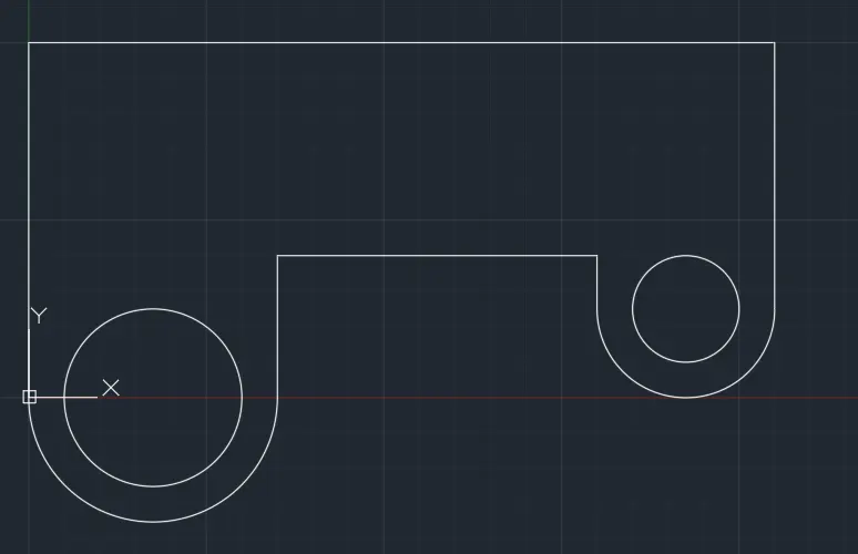
RECTANGLE Command: REC
Specify first corner point or [Chamfer/Elevation/Fillet/Thickness/Width]: 20,60
Specify other corner point or [Area/Dimensions/Rotation]: @70,30
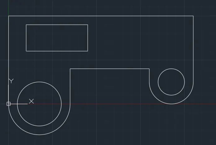
RECTANGLE Command: REC
Specify first corner point or [Chamfer/Elevation/Fillet/Thickness/Width]: 120,60
Specify other corner point or [Area/Dimensions/Rotation]: @70,30
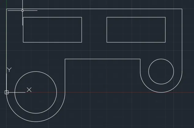
FILLET Command: F
Current settings: Mode = TRIM, Radius = 0.0000
Select first object or [Undo/Polyline/Radius/Trim/Multiple]: R
Specify fillet radius <0.0000>: 15
Select first object or [Undo/Polyline/Radius/Trim/Multiple]: M
Select first object or [Undo/Polyline/Radius/Trim/Multiple]:
Select second object or shift-select to apply corner or [Radius]:
Select first object or [Undo/Polyline/Radius/Trim/Multiple]:
Select second object or shift-select to apply corner or [Radius]:
Select first object or [Undo/Polyline/Radius/Trim/Multiple]:
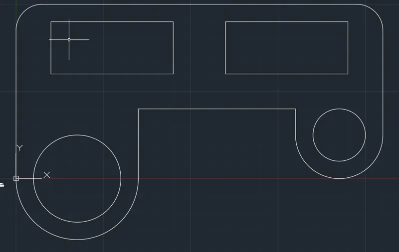
FILLET Command: F
Current settings: Mode = TRIM, Radius = 15.0000
Select first object or [Undo/Polyline/Radius/Trim/Multiple]: R Specify fillet radius <15.0000>: 20
Select first object or [Undo/Polyline/Radius/Trim/Multiple]:
Select second object or shift-select to apply corner or [Radius]:
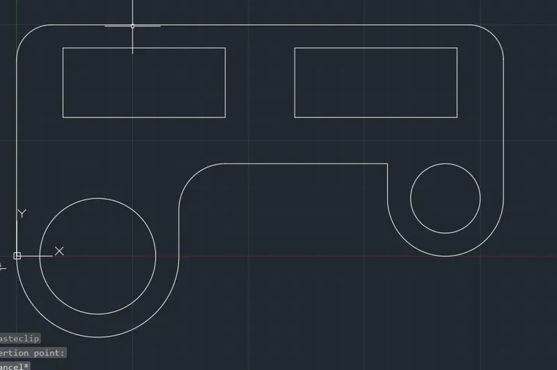
FILLET Command: F
Current settings: Mode = TRIM, Radius = 20.0000
Select first object or [Undo/Polyline/Radius/Trim/Multiple]: R Specify fillet radius <20.0000>: 6
Select first object or [Undo/Polyline/Radius/Trim/Multiple]:
Select second object or shift-select to apply corner or [Radius]:
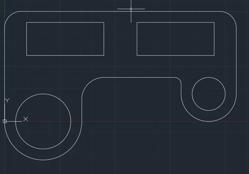
RESULTS :
- ALL DIMENSIONS ARE IN METERS ( m )
QUESTION : 8
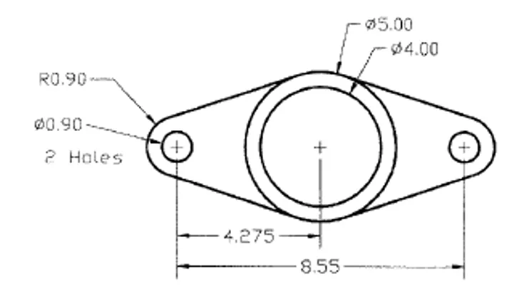
AIM : TO DRAW THE ABOVE FIGUREBY USING AUTOCAD
PROCEDURE :
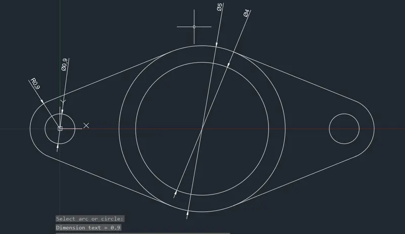
CIRCLE Command: C
Specify center point for circle or [3P/2P/Ttr (tan tan radius)]: 0,0
Specify radius of circle or [Diameter] <15.0000>: 0.9
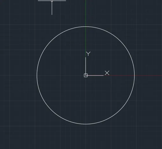
CIRCLE Command: C
Specify center point for circle or [3P/2P/Ttr (tan tan radius)]: 0,0
Specify radius of circle or [Diameter] <0.9000>: D Specify diameter of circle <1.8000>: 0.9
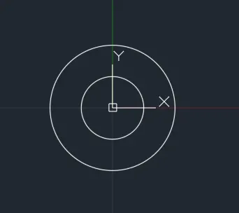
CIRCLE Command: C
Specify center point for circle or [3P/2P/Ttr (tan tan radius)]: 4.275,0
Specify radius of circle or [Diameter] <0.4500>: D Specify diameter of circle <0.9000>: 5
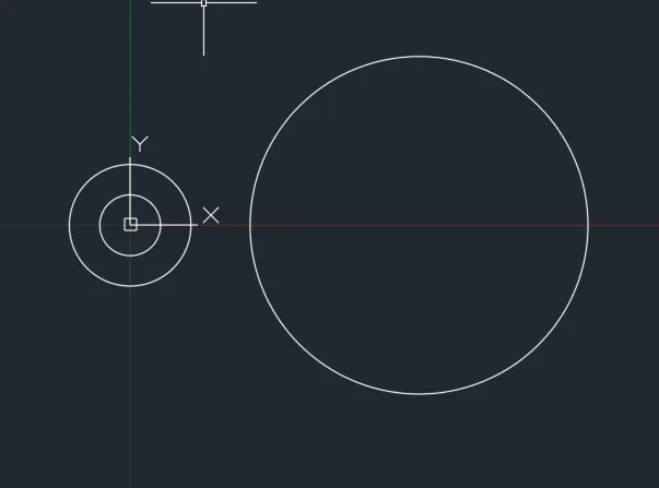
CIRCLE Command: C
Specify center point for circle or [3P/2P/Ttr (tan tan radius)]: 4.275,0
Specify radius of circle or [Diameter] <2.5000>: D Specify diameter of circle <5.0000>: 4
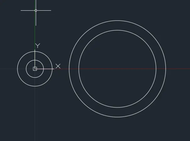
CIRCLE Command: C
Specify center point for circle or [3P/2P/Ttr (tan tan radius)]: 8.55,0
Specify radius of circle or [Diameter] <2.0000>: 0.9
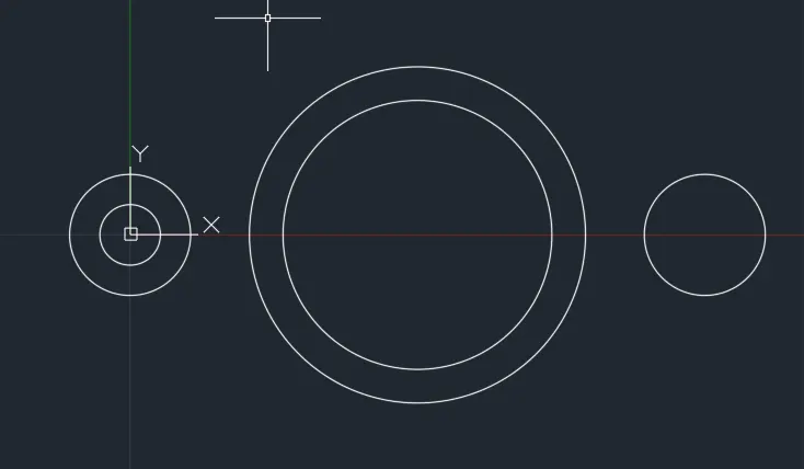
CIRCLE Command: C
Specify center point for circle or [3P/2P/Ttr (tan tan radius)]: 8.55,0
Specify radius of circle or [Diameter] <0.9000>: D Specify diameter of circle <1.8000>: 0.9
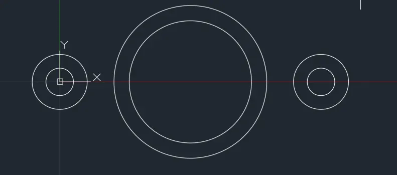
LINE Command: L
Specify first point:
>>Enter new value for ORTHOMODE <0>:
Resuming LINE command.
Specify first point: _tan to
Specify next point or [Undo]: _tan to
Specify next point or [eXit/Undo]: *Cancel*
Command: LINE
Specify first point: _tan to
Specify next point or [Undo]: _tan to
Specify next point or [eXit/Undo]:
Command: Specify opposite corner or [Fence/WPolygon/CPolygon]:
Command: Specify opposite corner or [Fence/WPolygon/CPolygon]:
Command: MI MIRROR 2 found
Specify first point of mirror line:
Specify second point of mirror line:
Erase source objects? [Yes/No] :
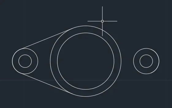
MIRROR Command: MI
Select objects: 1 found
Select objects: 1 found, 2 total
Select objects: Specify first point of mirror line:
Specify second point of mirror line:
Erase source objects? [Yes/No] :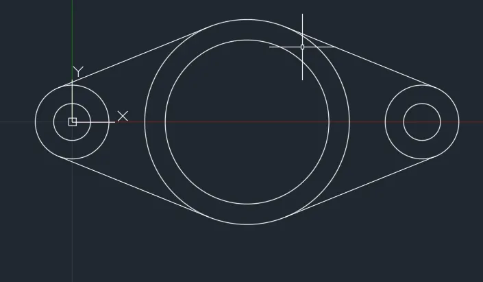
Command: TR TRIM
Current settings: Projection=UCS, Edge=None
Select cutting edges ...
Select objects or <select all>:
Select object to trim or shift-select to extend or [Fence/Crossing/Project/Edge/eRase]:
Select object to trim or shift-select to extend or [Fence/Crossing/Project/Edge/eRase/Undo]:
Select object to trim or shift-select to extend or [Fence/Crossing/Project/Edge/eRase/Undo]: *Cancel*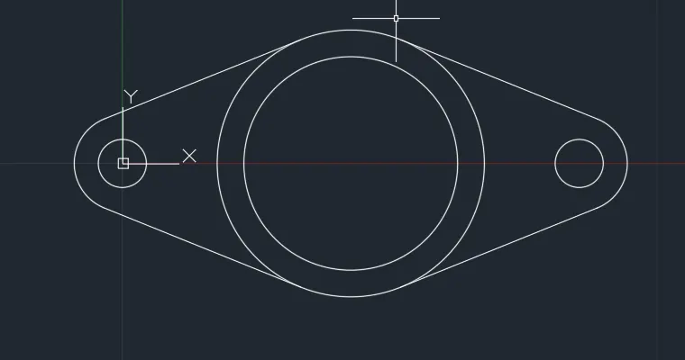
RESULTS :
- ALL DIMENSIONS ARE IN METERS ( m )
QUESTION : 9
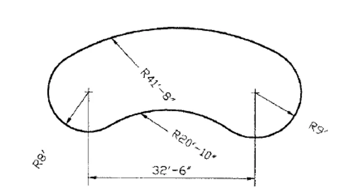
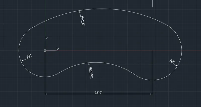
AIM : TO DRAW THE ABOVE FIGUREBY USING AUTOCAD
PROCEDURE :
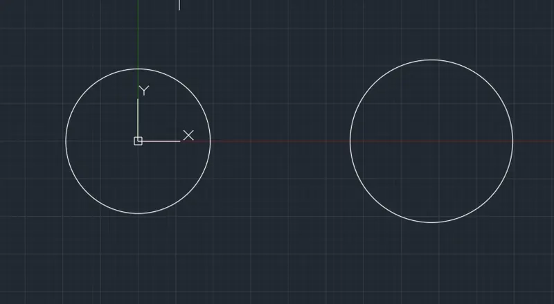
CIRCLE Command: C
Specify center point for circle or [3P/2P/Ttr (tan tan radius)]: 0,0
Specify radius of circle or [Diameter]: 8'
CIRCLE Command: c
Specify center point for circle or [3P/2P/Ttr (tan tan radius)]: 32'6",0
Specify radius of circle or [Diameter] <8'-0.00">: 9'
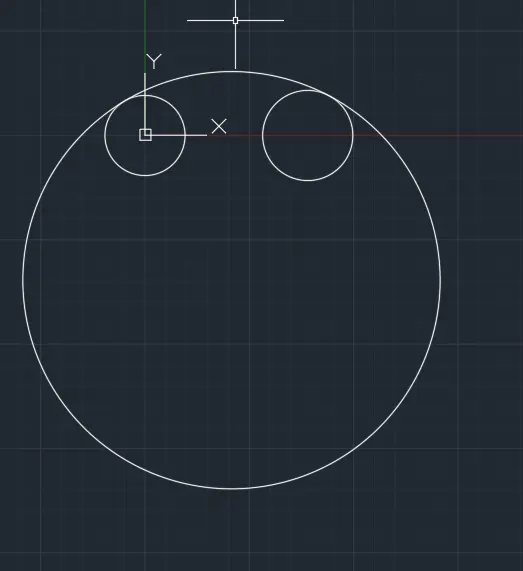
CIRCLE Command: C
Specify center point for circle or [3P/2P/Ttr (tan tan radius)]: T
Specify point on object for first tangent of circle:
Specify point on object for second tangent of circle:
Specify radius of circle <9'-0.00">: 41'8"
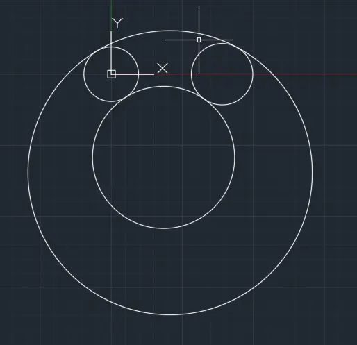
CIRCLE Command: C
Specify center point for circle or [3P/2P/Ttr (tan tan radius)]: T
Specify point on object for first tangent of circle:
Specify point on object for second tangent of circle:
Specify radius of circle <41'-8.00">: 20'10"
Command: TR TRIM
Current settings: Projection=UCS, Edge=None
Select cutting edges ...
Select objects or <select all>:
Select object to trim or shift-select to extend or [Fence/Crossing/Project/Edge/eRase]:
Select object to trim or shift-select to extend or [Fence/Crossing/Project/Edge/eRase/Undo]:
Select object to trim or shift-select to extend or [Fence/Crossing/Project/Edge/eRase/Undo]: *Cancel*
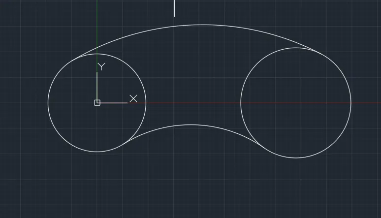
TRIM Command: TR
Current settings: Projection=UCS, Edge=None
Select cutting edges ...
Select objects or <select all>:
Select object to trim or shift-select to extend or [Fence/Crossing/Project/Edge/eRase]:
Select object to trim or shift-select to extend or [Fence/Crossing/Project/Edge/eRase/Undo]:
Select object to trim or shift-select to extend or [Fence/Crossing/Project/Edge/eRase/Undo]: *Cancel*
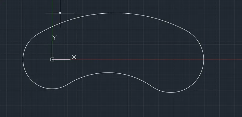
RESULTS :
- ALL DIMENSIONS ARE IN FEETS AND INCHES
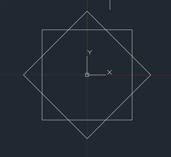
QUESTION : 10
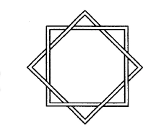
AIM : TO DRAW THE ABOVE FIGUREBY USING AUTOCAD
PROCEDURE :
POLYGON Command: POL
POLYGON Enter number of sides <4>: 4
Specify center of polygon or [Edge]: 0,0
Enter an option [Inscribed in circle/Circumscribed about circle] : i
Specify radius of circle: 5
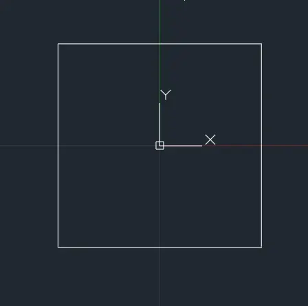
POLYGON Command: POL
POLYGON Enter number of sides <4>: 4
Specify center of polygon or [Edge]: 0,0
Enter an option [Inscribed in circle/Circumscribed about circle] : i
Specify radius of circle: 5
ROTATE Command: RO
Current positive angle in UCS: ANGDIR=counterclockwise ANGBASE=0
1 found
Specify base point:
Specify rotation angle or [Copy/Reference] <0>: 45
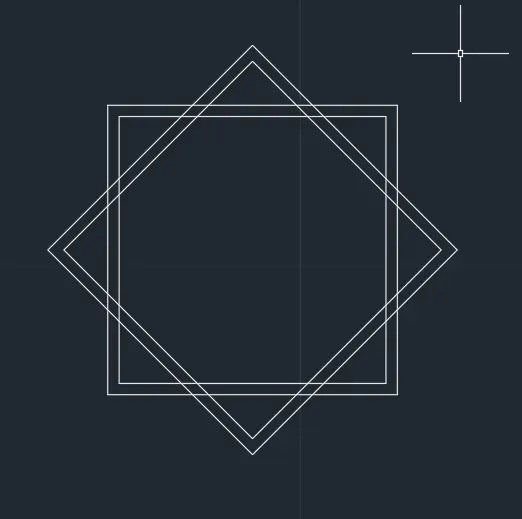
OFFSET Command: O
Current settings: Erase source=No Layer=Source OFFSETGAPTYPE=0
Specify offset distance or [Through/Erase/Layer] : 0.3
Select object to offset or [Exit/Undo] :
Specify point on side to offset or [Exit/Multiple/Undo] :
Select object to offset or [Exit/Undo] :
Specify point on side to offset or [Exit/Multiple/Undo] :
Select object to offset or [Exit/Undo] : *Cancel*
Command: TR TRIM
Current settings: Projection=UCS, Edge=None
Select cutting edges ...
Select objects or <select all>:
Select object to trim or shift-select to extend or [Fence/Crossing/Project/Edge/eRase]:
Select object to trim or shift-select to extend or [Fence/Crossing/Project/Edge/eRase/Undo]:
Select object to trim or shift-select to extend or [Fence/Crossing/Project/Edge/eRase/Undo]: *Cancel*
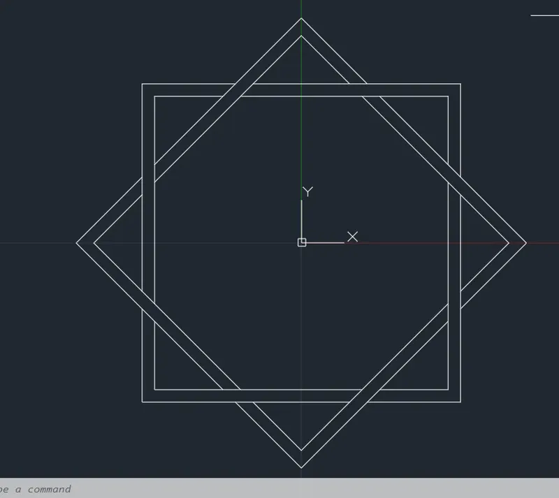
RESULTS :
- ALL DIMENSIONS ARE IN METERS ( m )
QUESTION : 11
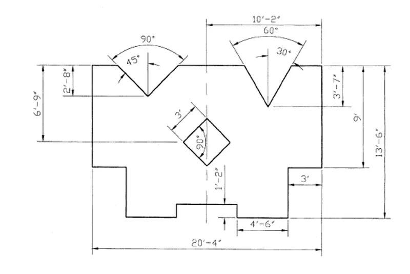
AIM : TO DRAW THE ABOVE FIGUREBY USING AUTOCAD
PROCEDURE :
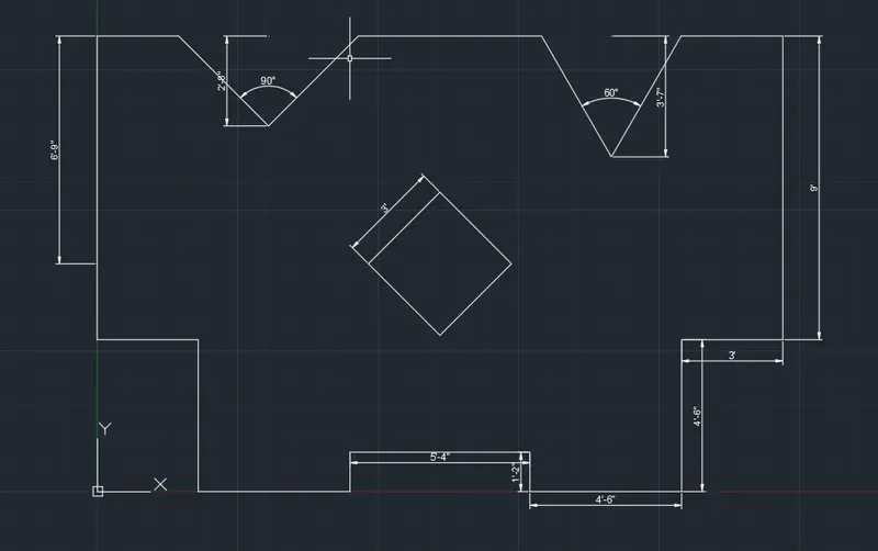
LINE Command: L
Specify first point: 0,4'6"
Specify next point or [Undo]: 3'
Specify next point or [eXit/Undo]: 4'6"
Specify next point or [Close/eXit/Undo]: 4'6"
Specify next point or [Close/eXit/Undo]: 1'2"
Specify next point or [Close/eXit/Undo]: 5'4"
Specify next point or [Close/eXit/Undo]: 1'2"
Specify next point or [Close/eXit/Undo]: 4'6"
Specify next point or [Close/eXit/Undo]: 4'6"
Specify next point or [Close/eXit/Undo]: 3'
Specify next point or [Close/eXit/Undo]: 9'
Specify next point or [Close/eXit/Undo]: 20'4"
Specify next point or [Close/eXit/Undo]: C
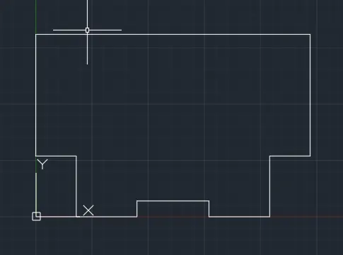
OFFSET Command: O
Current settings: Erase source=No Layer=Source OFFSETGAPTYPE=0
Specify offset distance or [Through/Erase/Layer] : 6'9"
Select object to offset or [Exit/Undo] :
Specify point on side to offset or [Exit/Multiple/Undo] :
Select object to offset or [Exit/Undo] :
OFFSET Command: O
Current settings: Erase source=No Layer=Source OFFSETGAPTYPE=0
Specify offset distance or [Through/Erase/Layer] <6'-9.00">: 10'2"
Select object to offset or [Exit/Undo] :
Specify point on side to offset or [Exit/Multiple/Undo] :
Select object to offset or [Exit/Undo] : *Cancel*
POLYGON Command: POL
POLYGON Enter number of sides <4>:
Specify center of polygon or [Edge]: E Specify first endpoint of edge: Specify second endpoint of edge: 3'
Command: Specify opposite corner or [Fence/WPolygon/CPolygon]:
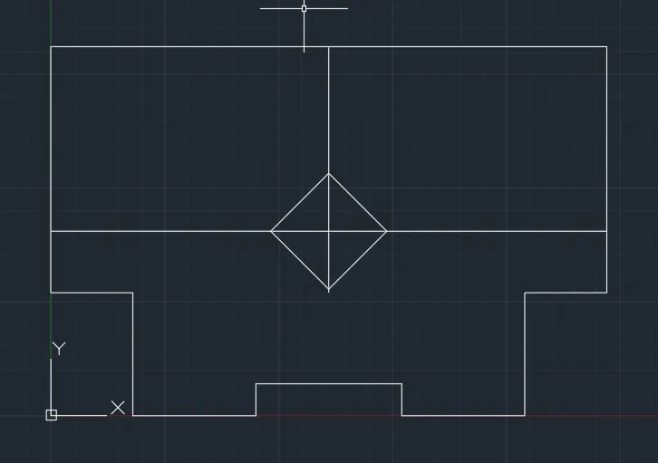
OFFSET Command: O
Current settings: Erase source=No Layer=Source OFFSETGAPTYPE=0
Specify offset distance or [Through/Erase/Layer] <10'-2.00">: 2'8"
Select object to offset or [Exit/Undo] :
Specify point on side to offset or [Exit/Multiple/Undo] :
Select object to offset or [Exit/Undo] : *Cancel*
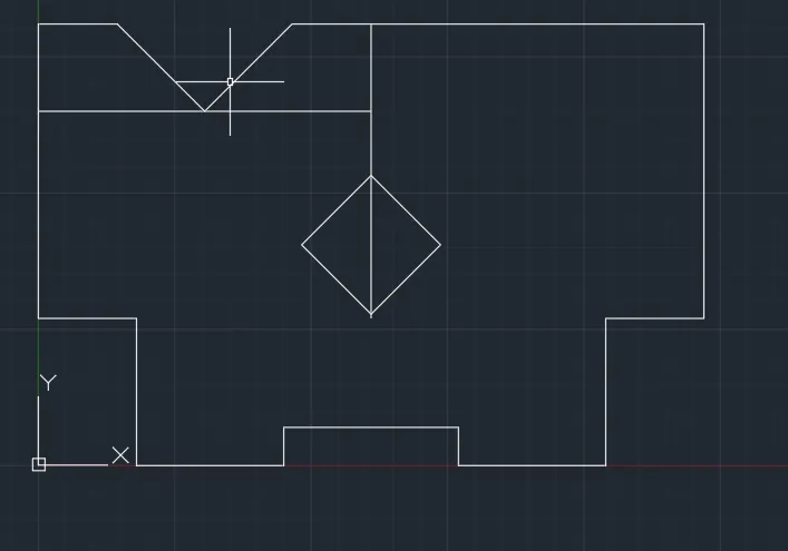
LINE Command: L
Specify first point:
Specify next point or [Undo]:
>>Enter new value for ORTHOMODE <1>:
Resuming LINE command.
Specify next point or [Undo]: <45
Angle Override: 45
Specify next point or [Undo]:
Specify next point or [eXit/Undo]: *Cancel*
LINE Command: L
Specify first point:
Specify next point or [Undo]: <135
Angle Override: 135
Specify next point or [Undo]:
Specify next point or [eXit/Undo]: *Cancel*
Command: TR TRIM
Current settings: Projection=UCS, Edge=None
Select cutting edges ...
Select objects or <select all>:
Select object to trim or shift-select to extend or [Fence/Crossing/Project/Edge/eRase]:
Select object to trim or shift-select to extend or [Fence/Crossing/Project/Edge/eRase/Undo]:
Select object to trim or shift-select to extend or [Fence/Crossing/Project/Edge/eRase/Undo]: *Cancel*
OFFSET Command: O
Current settings: Erase source=No Layer=Source OFFSETGAPTYPE=0
Specify offset distance or [Through/Erase/Layer] <2'-8.00">: 3'7"
Select object to offset or [Exit/Undo] :
Specify point on side to offset or [Exit/Multiple/Undo] :
Select object to offset or [Exit/Undo] : *Cancel*
Command: LINE
Specify first point:
Specify next point or [Undo]: <60
Angle Override: 60
Specify next point or [Undo]:
Specify next point or [eXit/Undo]: *Cancel*
LINE Command: L
Specify first point:
Specify next point or [Undo]:
>>Enter new value for ORTHOMODE <1>:
Resuming LINE command.
Specify next point or [Undo]: <120
Angle Override: 120
Specify next point or [Undo]:
Specify next point or [eXit/Undo]: *Cancel*
Command: TR TRIM
Current settings: Projection=UCS, Edge=None
Select cutting edges ...
Select objects or <select all>:
Select object to trim or shift-select to extend or [Fence/Crossing/Project/Edge/eRase]:
Select object to trim or shift-select to extend or [Fence/Crossing/Project/Edge/eRase/Undo]:
Select object to trim or shift-select to extend or [Fence/Crossing/Project/Edge/eRase/Undo]: *Cancel*
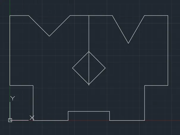
RESULTS :
- ALL DIMENSIONS ARE IN METERS ( m )