Sketch a G+1 residential plan according to Vaastu Shastra and Calculation of Loads as per IS code
Sketch a G+1 floor residential plan, according to Vaastu Shastra, and list down the names of the structural drawings required to be provided to the site for construction.
Also, assume the sizes of the structural elements (Column, Beam, Slab, etc.,) and accordingly calculate the individual corresponding loads from the members as per IS code.
AIM :
Sketch a G+1 floor residential plan, according to Vaastu Shastra, and list down the names of the structural drawings required to be provided to the site for construction.
Also, assume the sizes of the structural elements (Column, Beam, Slab, etc.,) and accordingly calculate the individual corresponding loads from the members as per IS code.
GROUND FLOOR :
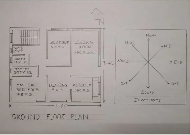
( Dimensions are in meters )
Dimensions of Ground Floor Plan :
Living room : 3.60m X 5.85M
Kitchen room : 3.60m X 3m
Dining room : 3m X 3m
Master bed room : 4.3m X 3m
Bed room : 3m X 4.5m
Toilet : 3.25m X 1.2m
Bath : 2.4m X 1m
Water coset : 1.2m X 1m
FIRST FLOOR PLAN :
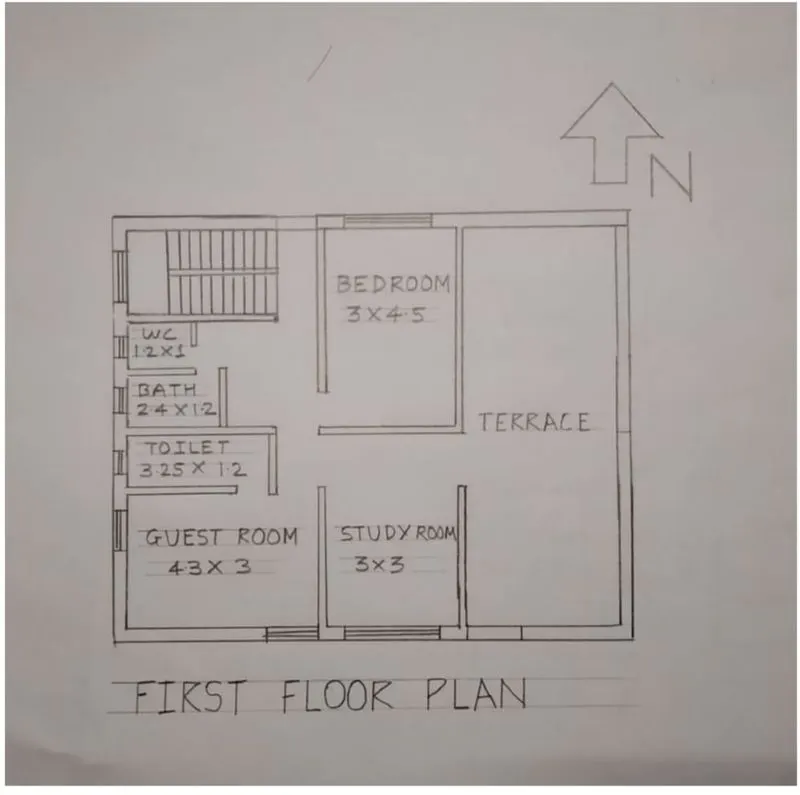
( Dimensions are in meters )
Dimensions of Ground Floor Plan :
Guest room : 4.3m X 3m
Bed room : 3m X 4.5m
Study room : 3m X 3m
Toilet : 3.25m X 1.2m
Bath : 2.4m X 1m
Water coset : 1.2m X 1m
OTHER DIMENSIONS :
Thickness of external wall - 0.23m ( 230mm )
Thickness of internal wall - 0.15m ( 150mm )
Thickness of slab - 0.25m ( 250mm )
Dimensions of column - 0.3m X 0.3m
Dimensions of beam - 0.3m X 0.45m
Height of the wall of each floor - 3m
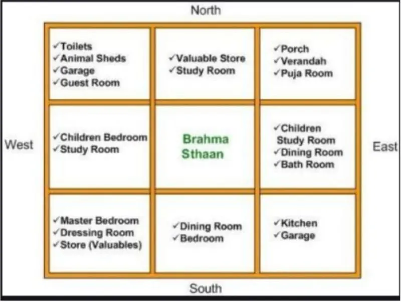
Vastu Shastra followed during planning -
- Entrance of the house is provided in the east direction which is the symbol of progress in life
- Living room is placed in north east direction.
- Master bedroom is placed in south west position this direction brings good health and prosperity.
- Kitchen is placed in south east direction.
- study room is placed in east direction.
- Staircase is placed at north west corner
- Bath room, WC and toilet is placed in west direction
LIST OF DRAWINGS PROVIDED AT THE CONSTRUCTION PROJECT :
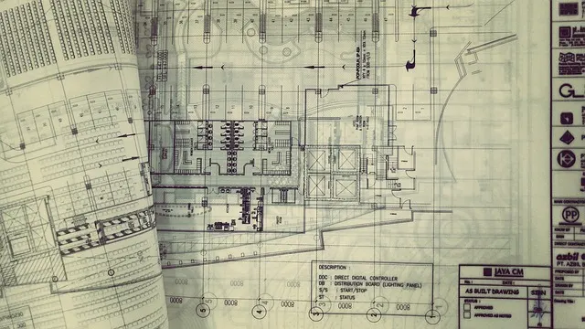
- Architectural Drawings
- Electrical Drawings
- Plumbing Drawings
- Structural Drawings
- Fire Fighting Drawings
- HVAC Drawings
An architectural drawing is a technical drawing of a building (or building project) that is used by architects to develop a design idea into a coherent proposal, to communicate ideas and concepts, to convince clients of the merits of a design, to enable a building contractor to construct it, as a record of the completed work, and to make a record of a building that already exists.
The following are typical components found in a full set of 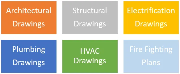 Architectural Construction Drawings:
- Setting Out Plan
- Floor Plans
- Elevation Drawings
- Section Drawings
- Working Drawings
- Opening Schedules
- Rood Drainage Plan
- Flooring Plan
- Furniture Plan
- Typical Details
These drawings shows the location of electrical equipment and their layout in the building.
- Electrical Legend
- Floor Lighting Plan
- Floor Power Plan
- Single Line Diagram
- Fire Alarm Layout
- Floor Sound System and CCTV Camera
- Equivalency Chart
- Lightening Protection Earthing Details
- Legend and General Notes
- Sewerage and Rainwater Layout Plan
- Manhole Schedule
- Plumbing Construction Details
- Water Supply Layout
These drawings show the support system of the building like how the building is standing, what are its structural components, what is the strength of the building and how beams, columns, stairs, slabs etc. are connected and thus like.
- General Notes
- Typical sections
- Foundation excavation plan
- Footing sections
- Ground floor column plan
- Column sections
- Ground floor plinth beams plan
- Plinth beams sections
- Ground floor beam plan
- Beam sections
- Ground floor slab bottom rebar detail
- Ground floor slab top rebar detail
- Ground floor slab section
- Overhead water tank design
- Septic tank design
5. Fire Fighting Drawings
- Legend and Notes
- Fire Fighting Layout Plan (For Each Floor)
6. HVAC Drawings
- Legend and General Notes
- AC Layout Plan (for each Floor)
- Equipment Schedule and Installation Detail
CALCULATION OF LOAD :
DEAD LOAD CALCULATION :
Dead load of column
Dimension of column - 0.3m X 0.3m ( 300mm X 300mm )
Height of column - 6.5m
Total volume of concrete = 0.3 X 0.3 X 6.5 = 0.585m^3
Unit weight of RCC = 25 KN/m^3
Dead load of column = 25 X 0.585 = 14.62 KN
DEAD LOAD OF BEAMS :
Dimension of Beam - 0.3m X 0.45m ( 300mm X 450mm )
Total volume of concrete = 0.3 X 0.45 X 1 = 0.135m^3
Unit weight of RCC = 25 KN/m^3
Dead load of column = 25 X 0.135 = 3.375 KN
DEAD LOAD OF SLAB :
Slab is always designed for the span of 1m
Assume size of slab as 1m X 1m
Unit weight of RCC = 25 KN/m^3
Self weight of slab = 1 X 1 X 0.25 X 25 = 6.25 KN
DEAD LOAD OF WALLS :
Thickness of external wall - 0.23m ( 230mm )
Unit weight of brick wall = 20 KN/m^3
Height of wall = 3m
Load of wall on beam = 3 X 0.23 X 20 = 13.8 KN
Thickness of internal wall - 0.15m ( 150mm )
Unit weight of brick wall = 20 KN/m^3
Height of wall = 3m
Load of wall on beam = 3 X 0.15 X 20 = 9 KN
LIVE LOAD CALCULATIONS :
According to IS 875 Part 2
Bed room = 2 KN/m^2
Living room = 2KN/m^2
Bath = 2 KN/m^2
Terrace = 3 KN/m^2
Toilet = 2 KN/m^2
Staircase = 3 KN/m^2
Study room = 2 KN/m^2
Kitchen = 2 KN/m^2
WIND LOAD CALCULATION :
Wind load is designed only when the height of building exceeds 10m.
the hight of building is 6.5m which is less than 10m.
So the calculation of WIND LOAD is not Reqired
RESULTS :
- The plan is prepared by the Vaasthu shastra concept considerations of Vaasthu shastra
- The load calculations are done as per the IS code considerations