Creating Levels, Grids, Layout and model elements for a residential unit using REVIT
- What is BIM? Summarize the features of BIM and the benefits of using BIM over 2D CAD tools.
ANS.
Bim: BIM stands for Building Information Modeling. Building Information Modeling (BIM) is the foundation of digital transformation in the architecture, engineering, and construction (AEC) industry. BIM is used for creating and managing data during the design, construction, and operations process. BIM integrates multi-disciplinary data to create detailed digital representations that are managed in an open cloud platform for real-time collaboration. Using BIM gives you greater visibility, better decision-making, more sustainable options, and cost savings on AEC projects.
The benefits of BIM are through connecting teams, workflows, and data across the entire project lifecycle – from design and engineering to construction and operations – to realize better ways of working and better outcomes.
BIM is mainly classified into two categories:
- Computation
- Coordination
Benefits of using BIM over 2D CAD tools are:
- Th the help of BIM we can get a complete representation of the project.
- BIM is real time model we can change any part of the model and it will get reflected in the whole project.
- Improves schedulling.
- By using BIM, we can reduce the working time as compared to the 2D CAD tool.
- We can link the projects to complete the project with at most efficiency
- Understand the concept of Categories, Families, Elements, Instances in Revit. Go to Insert Tab, choose a category. Pick a family and element. Understand the instances and insert them into the Revit model.
ANS:
AIM: To Understand the concept of Categories, Families, Elements, Instances in Revit. Go to Insert Tab, choose a category. Pick a family and element. Understand the instances and insert them into the Revit model.
Categories: Families are divided into different categories such as lighting fixtures, plumbing, etc.
Families: Group of components is called families.
Elements: Everything in Revit Is called element.
Instances: These are available after loading the families. These will make the elements unique in the project.
Tools Used: Insert Tab, Load Family.
Procedure: Loading the families into the Project.
Step1: To load the components you have to click on insert tab and click on load family.

Step2: Then families will open then select the component that you want to loadf and click on open.
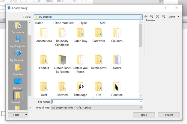
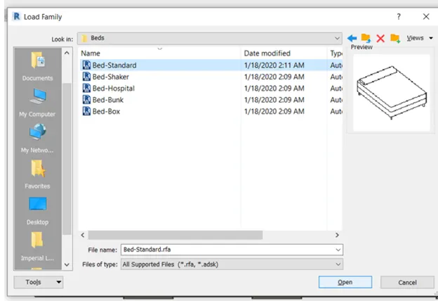
Step3: Then click on a component in the architecture tab and select the component you loaded in the properties.
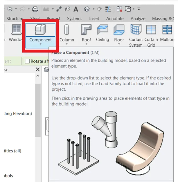
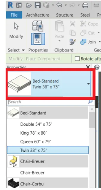
Step4: Then Place the component in the project where you want to use the cursor.
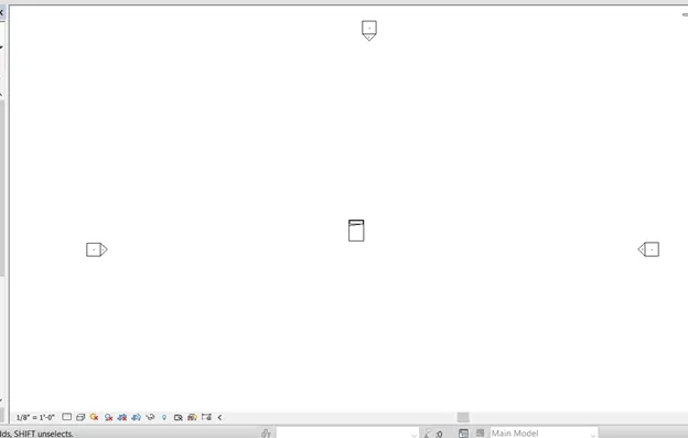
RESULT: By following the above procedure we had loaded or inserted the component
- Setting up a Project – Open a project file with an architectural template. Save the file with an appropriate name. Set up the project units to Imperial / Metric based on your convenience of modeling. Complete the project information under the Manage tab. Set up the maximum backups for project files to 3.
AIM: To Open a project file with an architectural template. Save the file with an appropriate name. Set up the project units and complete the project information then set up the maximum backups for project files to 3.
Tools used: Revit software, new file, save, manage tab, project units.
Procedure:
Step1: open a new file using an architectural template.
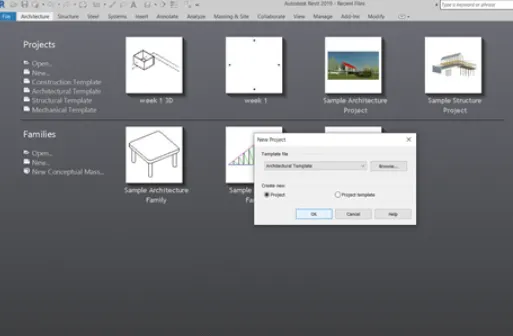
Step2: Save the project in the desired location with an appropriate name.
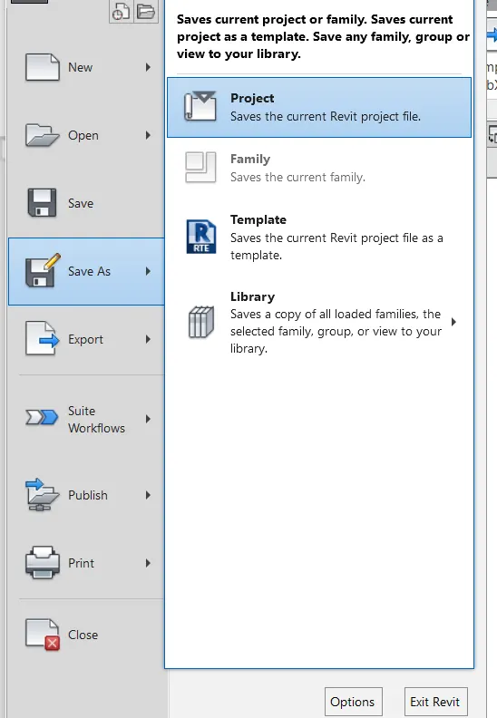
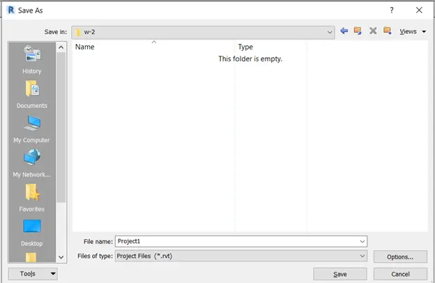
Step3: While saving we have to select backup files by clicking on options we have to select a minimum of 3.
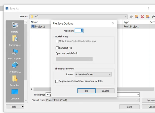
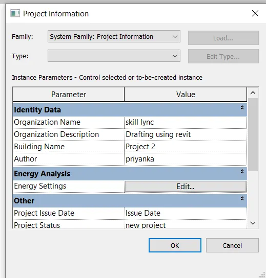
Step4: Now fill inthe project Info which is in the manage tab as required.
Step5: Now set the project units.
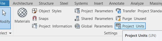
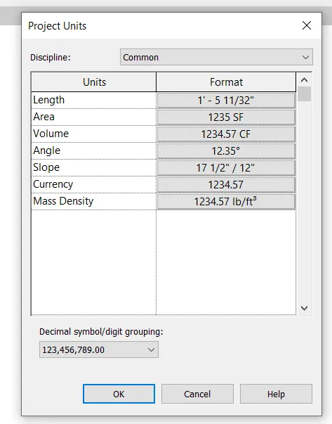
RESULT: By this, we had open a project file with an architectural template. Save the file with an appropriate name. Set up the project units to Imperial / Metric based on your convenience of modeling. Complete the project information under the Manage tab. Set up the maximum backups for project files to 3
4. Understand the concept of Levels and Grids. Follow the naming and conventions. Create the following Levels: (Convert to metric equivalents if the metric is your units)
Ground Floor @ 0’
First Floor @ 10’
Second Floor @ 20’
Roof @ 30’
Grids Transverse Grids A, B,C,D, E @ 10’ spacing
Longitudinal Grids from 1 to 10 @ 20’ spacing
ANS:
AIM: To create levels and grids as the following detailing:
Ground Floor @ 0’
First Floor @ 10’
Second Floor @ 20’
Roof @ 30’
Grids Transverse Grids A, B, C, D, E @ 10’ spacing
Longitudinal Grids from 1 to 10 @ 20’ spacing
Levels: These are used to represent floors of the structure in elevation.
Grids: These are used to represent all the walls in the project with the help of horizontal and vertical lines and notations.
Tools used: Revit software, Levels, Grids,
Procedure:
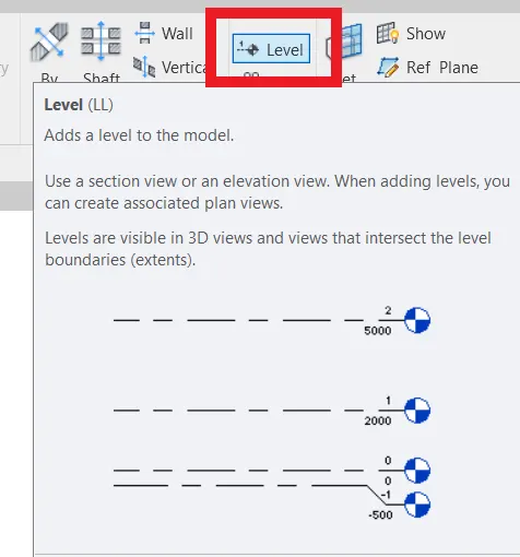
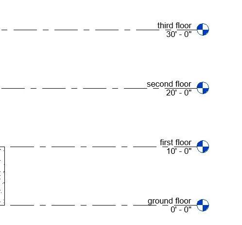
Step1: Click on levels in the architecture tab and levels will be activated only in elevations. So that we can create levels only in elevations. And create levels as
Ground Floor @ 0’
First Floor @ 10’
Second Floor @ 20’
Roof @ 30’
Step2: Now create the grids in level by clicking on the grid in the architecture tab and datum panel. Create grids as:
Transverse Grids A, B, C, D, E @ 10’ spacing
Longitudinal Grids from 1 to 10 @ 20’ spacing
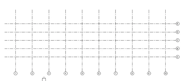
RESULT: By this, we had created levels and grids in the project with the details given in the question.
- 3D modeling of the residential unit – From looking at your house / or a place you aspire. Create a conceptual layout of the residential unit. You can measure using a tape or
you can access your residential plan to create a similar layout.
AIM: 3D modeling of the residential unit to create a conceptual layout
Tools used: Wall architecture, view, default 3D view.
Procedure:
Step1:Open a new project and save it at desired location with the appropriate name.
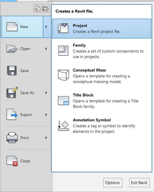
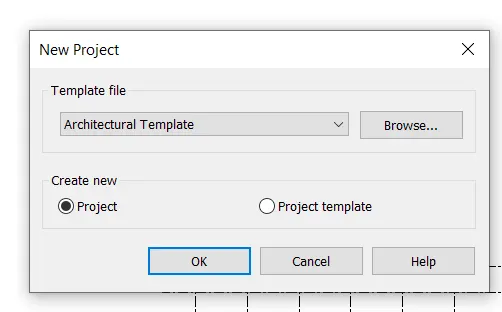
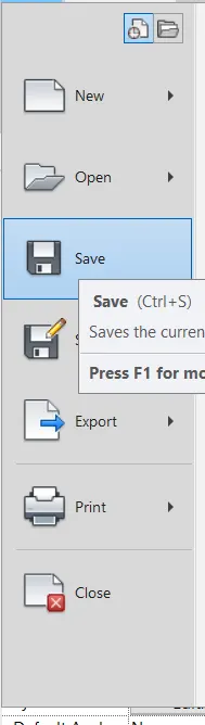
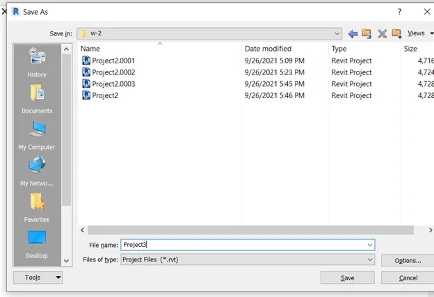
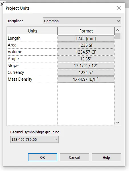
Step2: Set the project units as required.
Step3: Now select the wall architecture and select the required wall and create the layout of the residential plan.
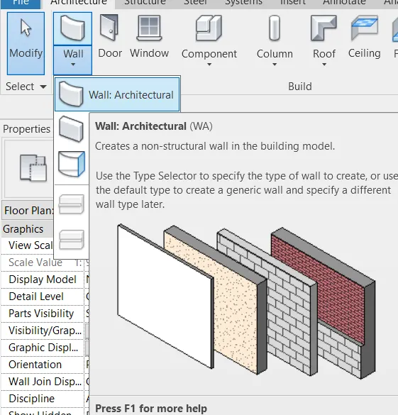
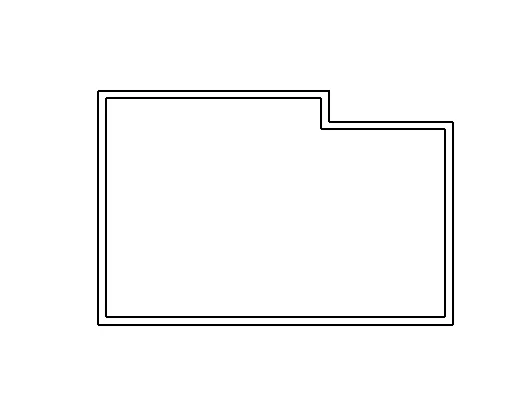
Step4: Now in the view tab click on 3D view to see the 3D view.
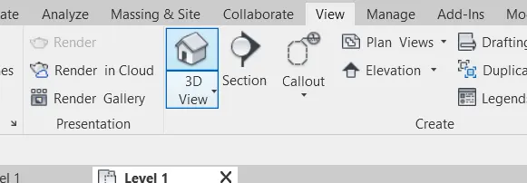
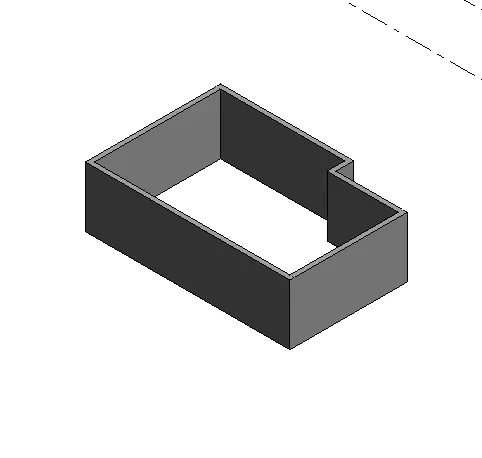
RESULT: By this, we had created a layout of the residential plan which is to be modeled further.
6) In the layout created draft the level of details you are planning to include – Dimensions of room, components you plan to add in the residential unit.
AIM: In the layout created draft the level of details you are planning to include – Dimensions of room, components you plan to add in the residential unit.
Tools used: Revit software, walls, project browser.
Procedure:
Step1: Now open the layout created/
Step2: Now we have to do interior detailing of the plan.
Step3: select the wall and create according to the plan.
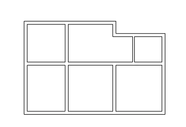
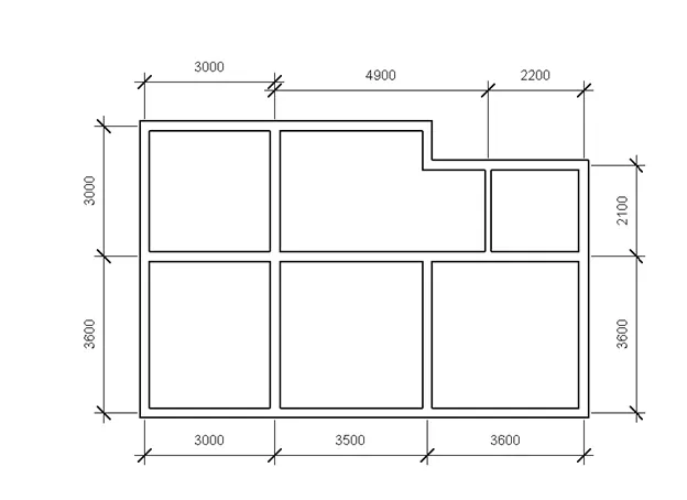
Step4: After that, the plan looks like above now Give dimensions for details.
Step5: Open the default 3D view to see the 3D view.
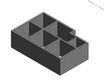
RESULT: By this, we can create our interior detailing to the layout which had been created for 3D modeling.
7) Identify the residential model elements such as Door, Windows, Tables, Chairs, Couch, Bed, Lamps from the library and insert them into the model.
AIM: Identify the residential model elements such as Door, Windows, Tables, Chairs, Couch, Bed, Lamps from the library and insert them into the model.
Tools used: Previous file, Insert, components, load family.
Procedure:
Step1: After with interior walls and dimensions we have to do interior detailing with doors, windows, families, etc.,
Step2: From the Insert tab use load family to load components and then use components in the architecture tab to place the components in the project.
Step3: And with the help of the cursor place the components at the appropriate place.
Step4: After placing all components required the plan looks like below.
NOTE: Doors and Windows can be loaded only at specific system family only. For example, the door will be loaded only in the door family.
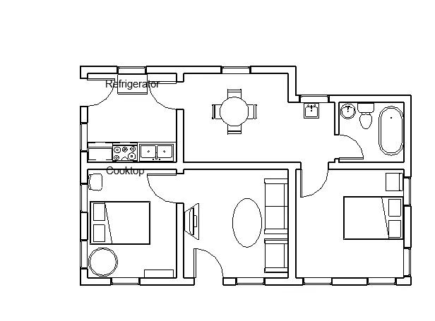
Step5: Now open the default 3D view to see in 3D view.
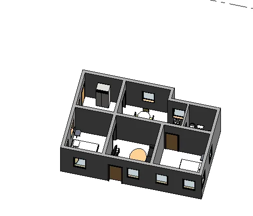
RESULT: By this, we will add components to the project like doors, windows, families, etc.