Creating Levels, Grids, Layout and model elements for a residential unit using REVIT
Aim 1:
What is BIM? Summarize the features of BIM and benefits of using BIM over 2D CAD tools.
Solution:
- BIM is the visual representation of the physical and functional characteristic of facility from inception onwards.
- It Serve as a shared information repository for collaboration throughout a facilities life cycle.
- Revit Building element are of three type:
- View Elements
- Model Elements
- Annotate Elements
- Annotation elements
- Datum elements
- Features of BIM:
- Easy access to information.
- Making the process more expressive.
- Compressive view of the project.
- Benefits of BIM:
- Complete Representation.
- Instant Updates.
- Time Constraints.
- Resource Tracking.
Aim 2:
Understand the concept of Categories, Families, Elements, Instances in Revit. Go to Insert Tab, choose a category. Pick a family and element. Understand the instances and insert it to Revit model
Solution:
Category: It is one of the Revit element, actually it control the organization , graphical representation and scheduling options of families with in the project.
Family: The family is a group of 2D or 3D information that serves to documentation element in the project. It defines parametrical graphical & documentation requirement also.
Type: Specific representation in a family defined by distinct parameter graphical and documentation characteristics which makes it unique from other types in family.
Instances: It is an individual representation of a type in the project defined by unique parametric graphical and documentation characteristics which makes unique from other instances in the project.
Steps:
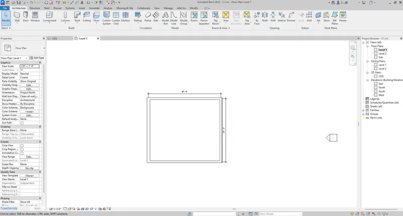
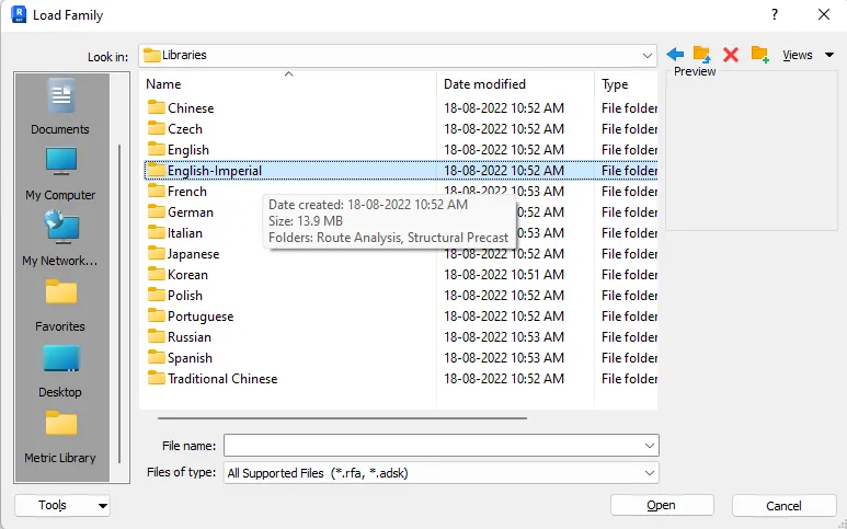
- Open Revit Project.
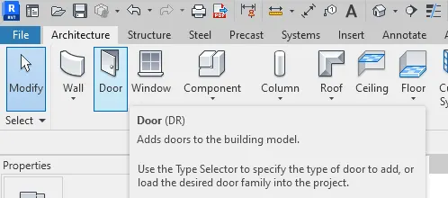
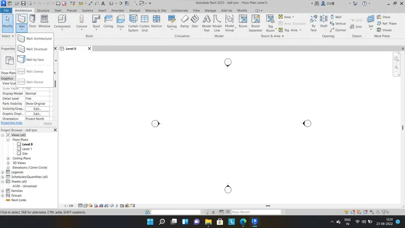
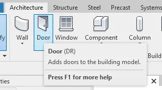
- Select the Door From Architecture Tab.
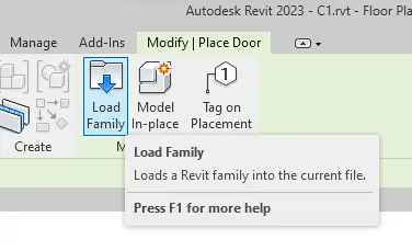
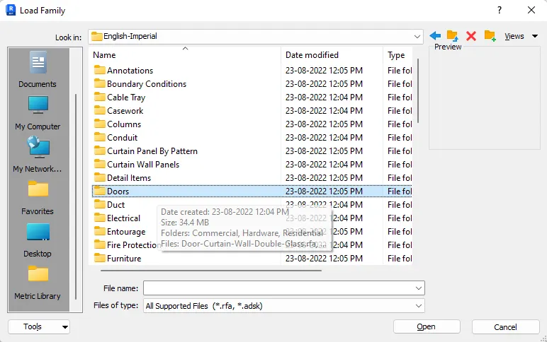
- Select the Load Family option in Modify Door Tab.
- Select English Imperial.
- Select Door Category.
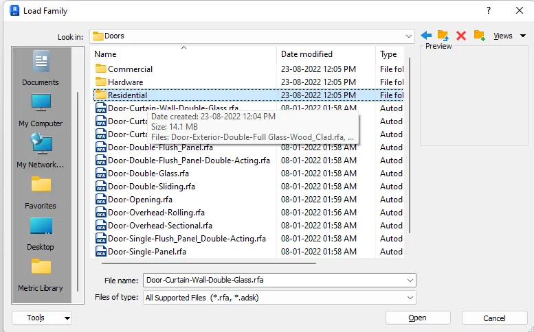
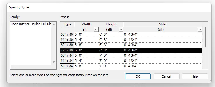
- Select the Type:
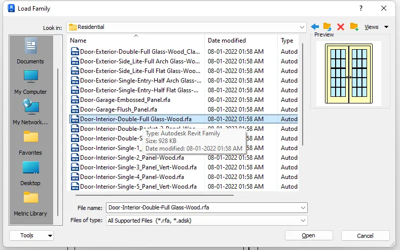
- Select the instance which we want.
- Specify the type again.
- Now insert the door in the plan.
Aim 3:
Setting up a Project – Open a project file with architectural template. Save the file with appropriate name. Set up the project units to Imperial / Metric based on your convenience of modelling. Complete the project information under Manage tab. Set up the maximum backups for project file to 3.
Procedure:
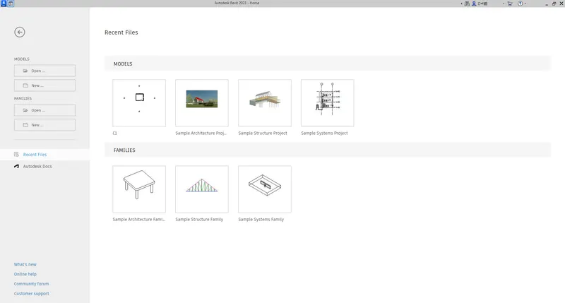
- Open Revit.
- Select the new in the modal category.
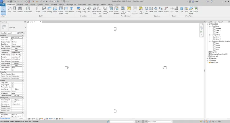
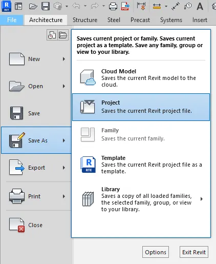
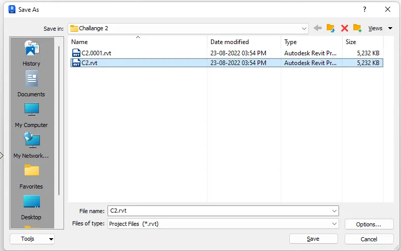
- Now save the project with the appropriate name in the system.
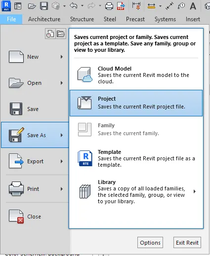
- Go to Save as then Select the project
- Save with the appropriate name.
- Go to Save as then Select the project
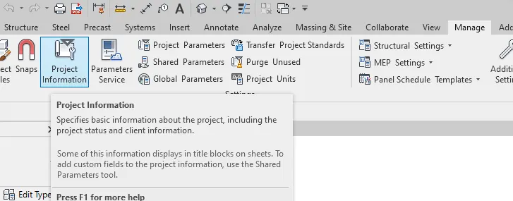
- Go to the manage tab and select the project information tool in it.
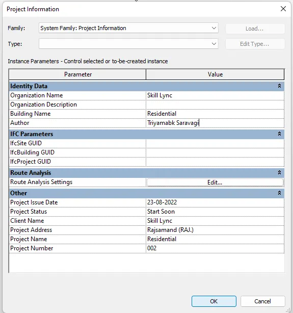
- Enter the Project Information in the box and select ok.
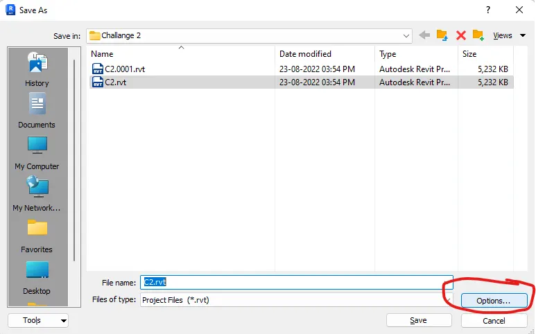
- again go to the save as > project option in the file tab to the left corner.
- Select the option button above the save button.
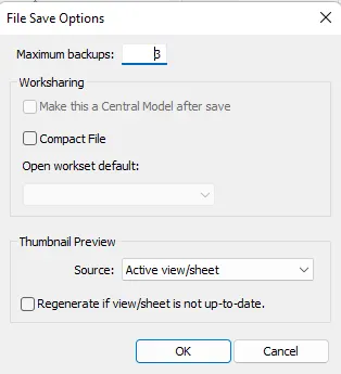
- Write 3 in Maximum Backups 3 and then select ok.
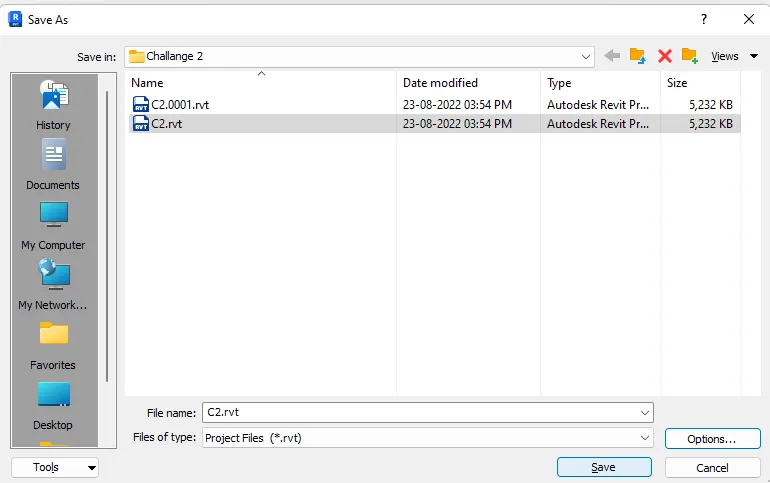
- Now save the file.
- Three backup files created.

Aim 4:
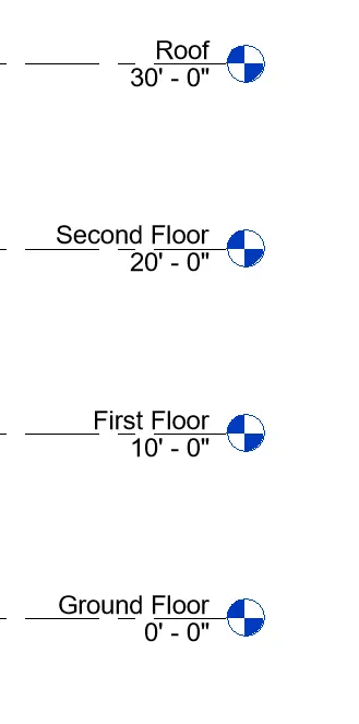
Understand the concept of Levels and Grids. Follow the naming and conventions. Create the following Levels: ( Convert to metric equivalents if metric is your units)
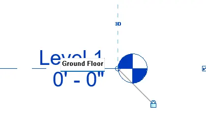
Ground Floor @ 0’
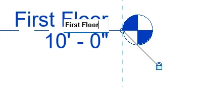
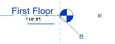
First Floor @ 10’
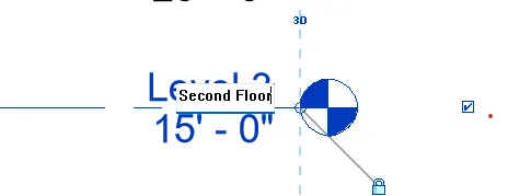
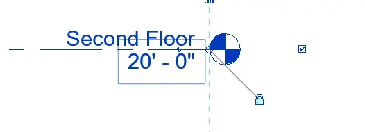
Second Floor @ 20’
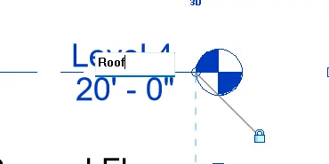
Roof @ 30’
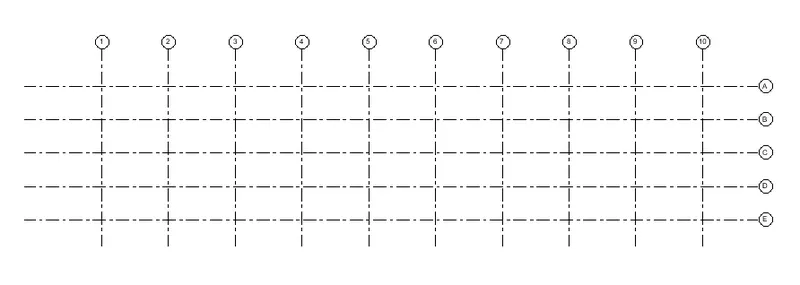
Grids Transverse Grids A, B,C,D, E @ 10’ spacing
Longitudinal Grids from 1 to 10 @ 20’ spacing
Procedure:
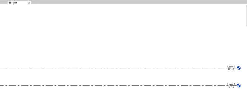
- Open the elevation view.
- Create 2 more levels above the level 2.
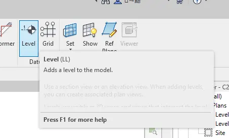
- Go to Architecture Tab and select the Level tool.
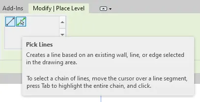
- Select the pick line tool and make offset of 5' & draw the levels.
- Go to Architecture Tab and select the Level tool.
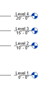
- click on the Level 1 and rename it as Ground Floor.
- Click on the Level 2 and rename it as First Floor.
- Click on the Level and Rename it as second floor.
- Click on the Level 4 and rename it as roof.
- Edit the Height of the First Floor to 10'.
- Edit the Height of the Second Floor to 20'
- Edit the height of the Roof to 30'.
- Open Ground Floor.
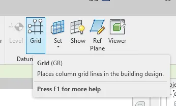
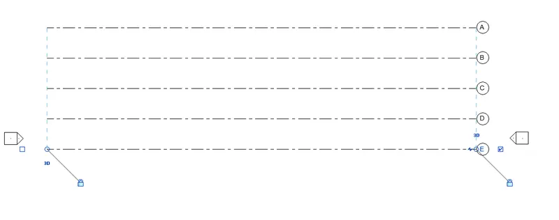
- open the Architecture tab and select the grid tool.
- use lline tool to draw the First grid line.
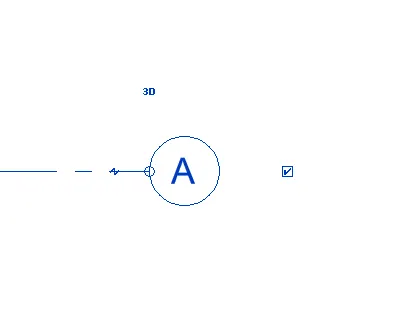
- Rename the grid 1 to A.
- Again Architecture>Grid Tool then Now select pick line tool and enter the offset of 10'
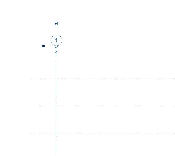
- Now select the line tool in grid and draw the Vertical grid as name 1.
- Mow take the pick line option and enter the offset of 20' and draw the grids trill 10.


Aim 5:
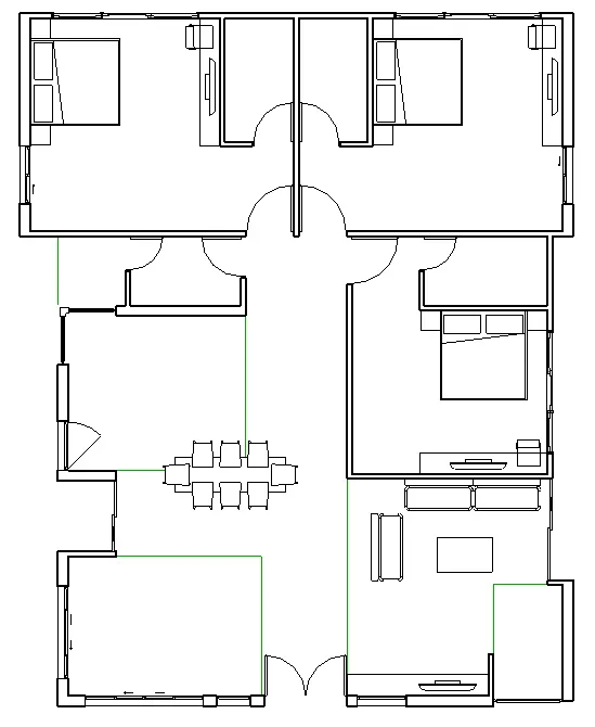
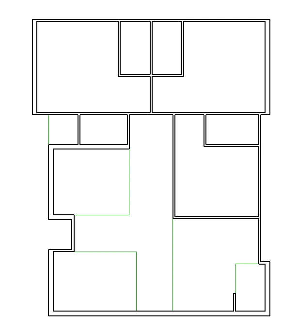
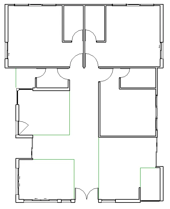
3D modelling of residential unit – From looking at your house / or a place you aspire. Create a conceptual layout of the residential unit. You can measure using a tape or
you can access your residential plan to create a similar layout.
Procedure:
- Select the wall tool in the Architecture tab.
- Change the wall reference line to wall face exterior.
- set the level of the wall.
- Base Constraint = Level 1.
- Top Constraint = Level 2.
- offset = 0'0"
- now draw the plan.
Result:
Aim 6:
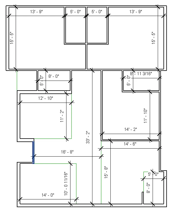
In the layout created draft the level of details you are planning to include – Dimensions of room, components you plan to add in the residential unit.
Procedure:
- Go to Annotate tab.
- Select the Aligned Dimension Tool.
- Set the Dimension measurement to Wall face.
- Now One by one Select the faces of wall from inside and Dimension the partitions.
Result:
Aim 7:
Identify the residential model elements such as Door, Windows, Tables, Chair, Couch, Bed, Lamps from the library and insert them to the model . Save the project for use
for Assignment 3
Procedure:
- Put the Doors Using Door tool in the architecture tab.
- Now use window tool and place the windows in the plan.
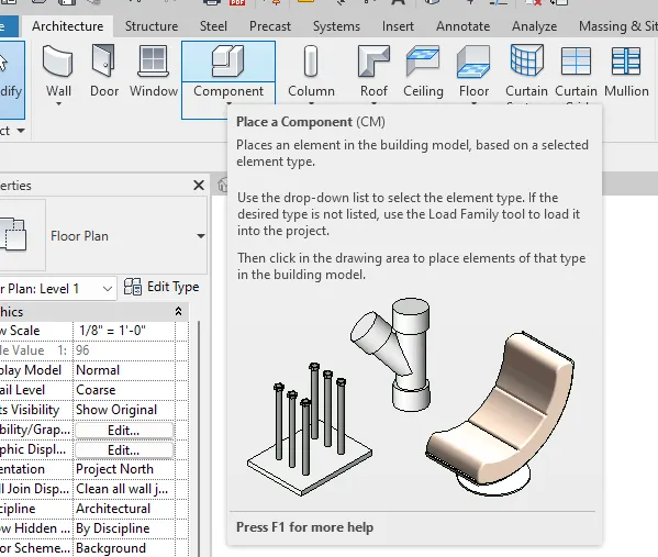
- Use the Place a Component tool in Architecture tab to Put the Table in the plan.
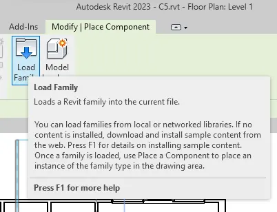
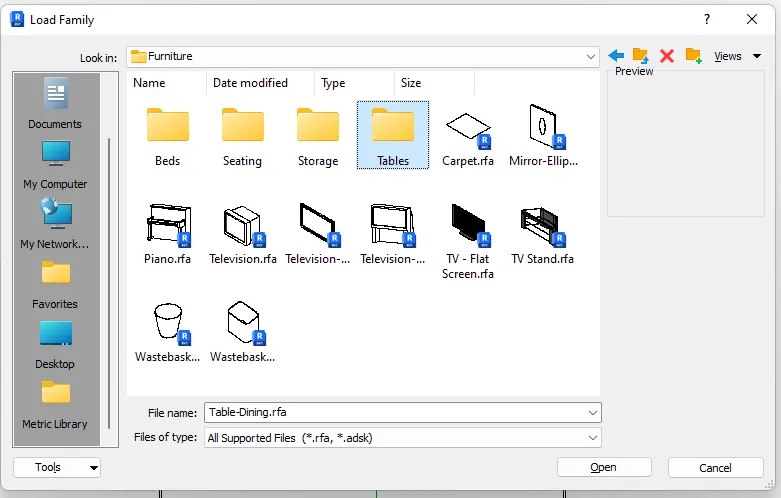
- Select the Load Family.
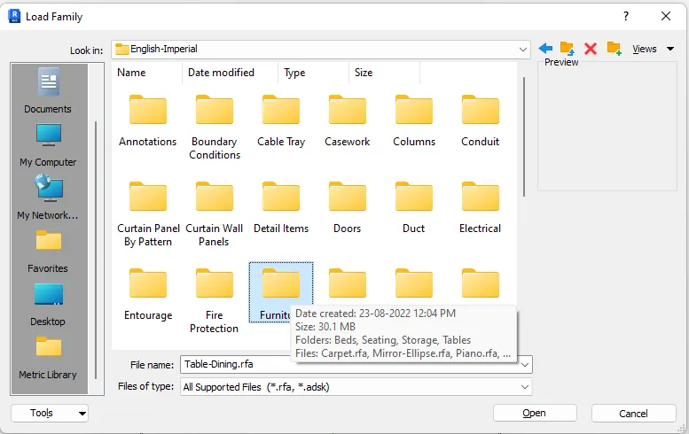
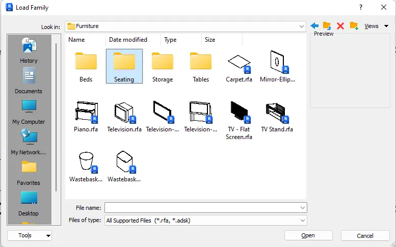
- Select the Furniture folder.
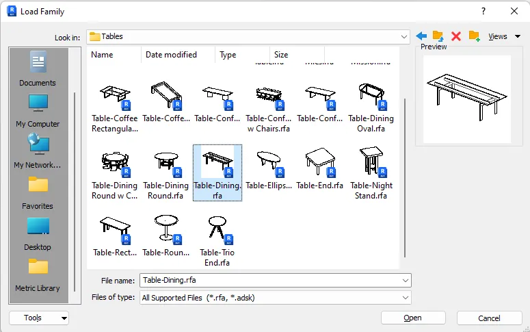
- Select the Table Folder.
- Select the table whichever is want.
- Similarly Now select the Seating in the furniture Folder.
- Now put the table and chair as per the plan requirement.
- Noe Put the Bed Furniture.
- Now Put the Couch in the plan using Components.
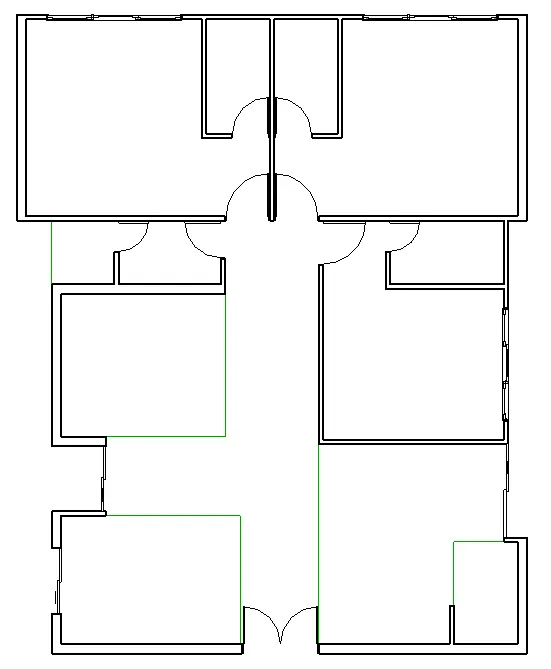
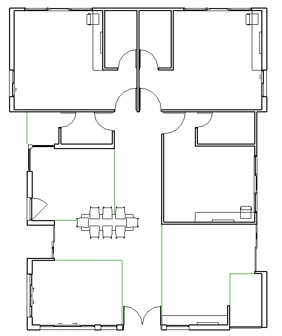
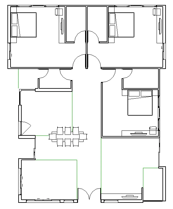
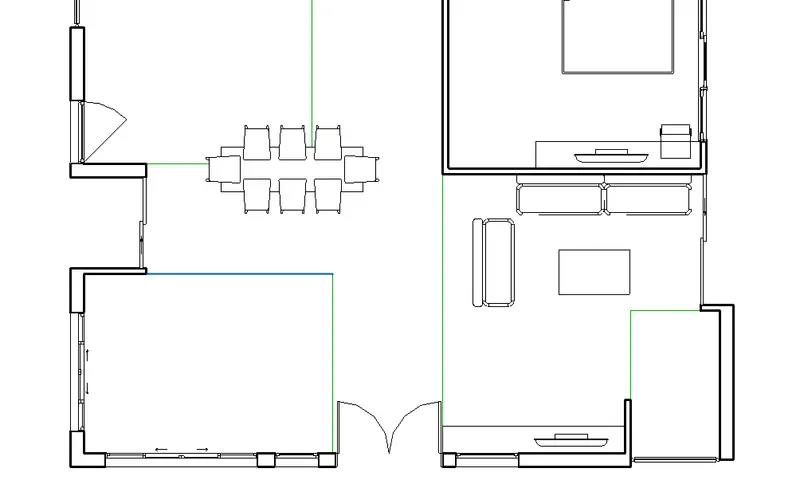
Final Result: