Creating Levels, Grids, Layout and model elements for a residential unit using REVIT
1Q:
Building Information Modelling (BIM) is an intelligent 3D model-based process that equips architecture, engineering, and construction professionals with the insight and tools to more efficiently plan, design, construct, and manage buildings and infrastructure. Autodesk Revit software is purpose-built for BIM.
In recent years, more architects and engineers have made the switch to building information modelling (BIM). The reasons are quite clear. BIM encourages a more collaborative environment. It also has a high focus on sustainability in building design. Firms can use BIM to create more environmentally-friendly buildings. Furthermore, they cut down on much of the manual work. Our teams become more productive, and the BIM method saves money for your firm.
While BIM is a methodology, we also need the right software to implement it. The Revit BIM software is among the most popular. One of the few digital design software packages created with BIM specifically in mind, Revit has helped many firms to make the difficult transition. It allows us to design singular models, and uses cloud computing to ensure every member of your team has access to the information they need.
BIM technology is:
The technology used in the AEC industry,
A process starting from the investor’s requirements, through design, construction stage, to the facility management during its lifetime.
The work of all project participants in the Common Data Environment,
3D model, which is a carrier of information and the dependencies of objects among each other,
Information closely linked to the 3D model, allowing them to be easily found and accurate,
General documentation which cannot be linked to the 3D model, necessary to carry out the investment process, appropriately named and placed in the CDE.
FEATURES OF BIM
Early detection of a collision
Faster design and construction
More precise planning
Visualization at an early stage of the project
Higher quality of performed work
Better communication in the project
Reducing delays and errors
Increasing efficiency and productivity
Competitiveness
Easy access to information
Project life cycle
Improvement of OSH (occupational safety and health).
BENEFITS OF USING BIM OVER 2D CAD TOOLS:
Revit offers several advantages to architects and engineers. Many of these benefits come from how closely it integrates with the BIM concept.
- BIM offers a more complete representation of a building’s design. It takes more than the building’s core components into account. For example, BIM allows you to design electrical and HVAC systems, as well as the building itself. This means the project team can take full advantage of the space and resources available.
- BIM pulls your documents into a single database. Several people can work on the same model and save it to the cloud. This allows for instant updates, so you won’t waste time searching for documents when you need to make changes.
- A BIM model will allow you to prefabricate important components ahead of time. You won’t have to adjust them based on the building design. Instead, such components are part of the initial design.
- You can provide much more to your clients using BIM than you could with CAD. The models you give to your clients update constantly as you work on your project. Your client can check in any time, which leads to quicker approval for milestones and more efficient project development.
- Resource tracking is a key component of BIM models. You’ll be able to figure out how much of each resource you need during the design stage. This improves the flow and efficiency of construction.
- Models created using 3D BIM software are intelligent, meaning each element placed in the model contains information about the element that can later be reused for other purposes in the project.
- 3D BIM offers considerable time savings over 2D CAD. In contrast to 2D CAD, change management is largely an automated task with 3D BIM. Because drawings are linked to the 3D model, all dimensional and geometric changes made in the model are automatically corrected on all relevant erection drawings and shop tickets.
- Using 3D BIM software can greatly cut down on potential errors. Naturally it's easier to identify interference between elements and spacial problems in 3D than 2D since you can effortlessly visualize the whole picture which can cut down on costly errors.
- 3D BIM makes collaboration among different teams easier than ever before. Using the same model and resources architects, engineers, and contractors can now effortlessly work together to design and construct a project.
2Q:
AIM: Understand the concept of Categories, Families, Elements, Instances in Revit. Go to Insert Tab, choose a category. Pick a family and element. Understand the instances and insert it to Revit model
INTRODUCTION:
Revit Element Hierarchy
Category: A Category controls the organization, visibility, graphical representations, and scheduling options of Families within the Project.
Family: A Family is a grouping of 2D and/or 3D information that serves to represent a discrete building or documentation element in the Project. It defines parametric, graphical, and documentation requirements.
Type: A Type is a specific representation in a Family defined by distinct parametric, graphical, and documentation characteristics which makes it unique from other Types in the Family.
Instance: An Instance is an individual representation of a Type in the Project defined by unique parametric, graphical, and documentation characteristics which makes it unique from other Instances in the Project.
PROCEDURE:
Open the Revit application
Select the architectural template under the projects tab to open the template.
save the file to a destination folder and name it as project 1
Now using the wall option in architectural tab create a rectangular wall as shown
In order to understand about the concept of Categories, Families, Elements, and Instances in Revit it can be known through by inserting a door.
CATAGORIES:
Under the insert tab select load family option to load the general family like door, window, wall etc.
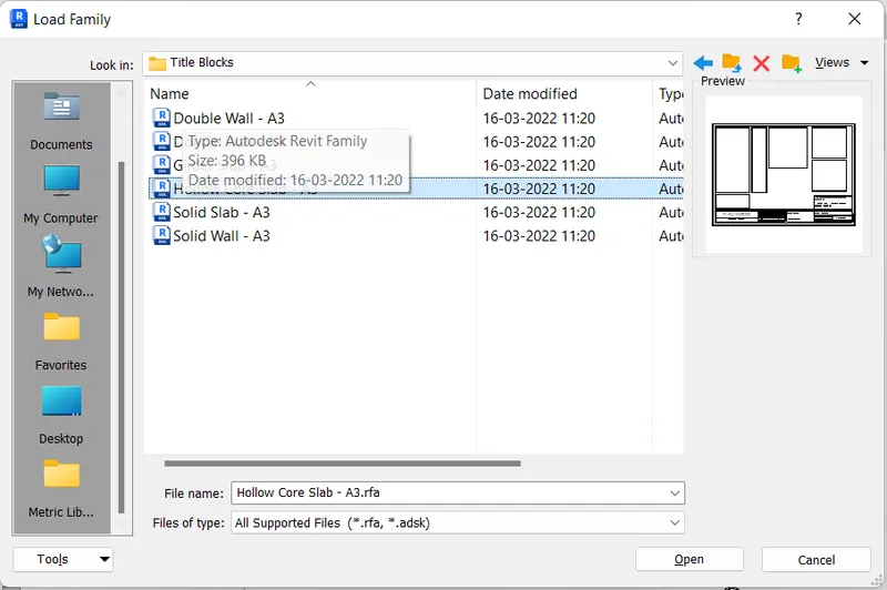
Load family dialogue box will appear as shown.
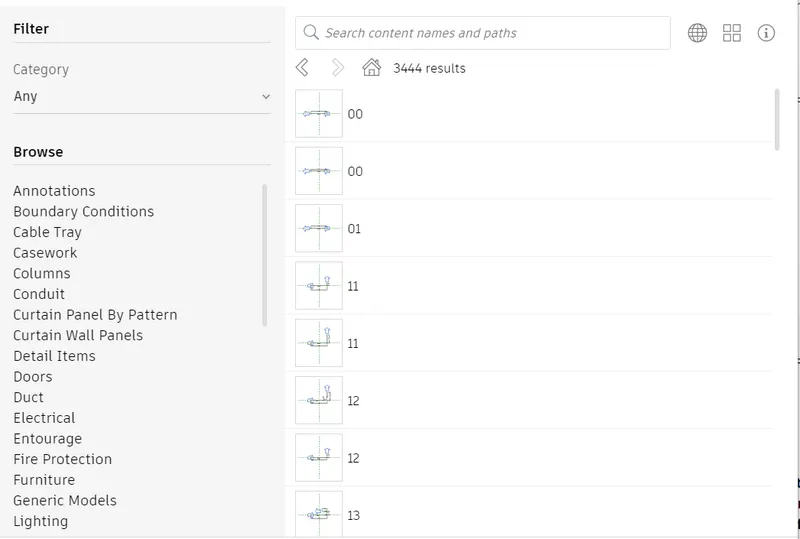
All of these for example the doors, duct, furniture etc. belongs to category.
FAMILIES:
Families are a group of elements which share a common property like parameters and similar graphical representations.
All of these are different types of door but they all are under individual families.
ELEMENTS:
They are the building blocks of the 3D model.
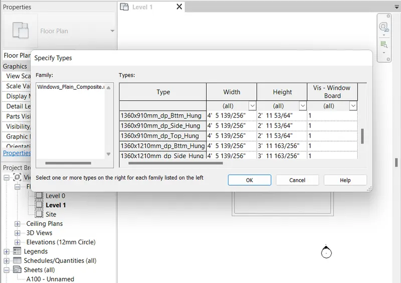
All of these doors (elements) comes under the individual family which we chose above.
INSTANCES:
These will be the final elements which are placed in the Revit model.
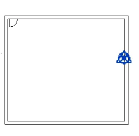
A suitable door was selected from the above list and placed at appropriate position.
3Q:
AIM: Setting up a Project – Open a project file with architectural template. Save the file with appropriate name. Set up the project units to Imperial / Metric based on your convenience of modelling. Complete the project information under Manage tab. Set up the maximum backups for project file to 3
INTRODUCTION:
The main objective of this task is to create a new architectural template. After the creation the template we have to save it with a suitable name. Then the desired unit that is metric was made default for that task. Then finally the project information details are entered by selecting the option from manage tab and maximum backup for this particular file was set to 3.
PROCEDURE:
Open the Revit application and click on architectural template under the project tab.
Using the Save as option from the file menu save it as a project in the desired folder.
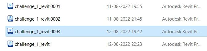
Click on the options at the bottom part of save as dialogue box to open the file save options dialogue box and in the maximum backup options place type 3 and click on ok
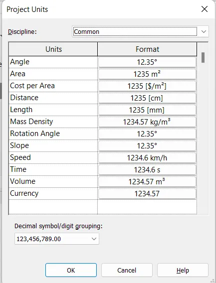
Under the manage tab select the project units and set the desired units that is metric and click ok.
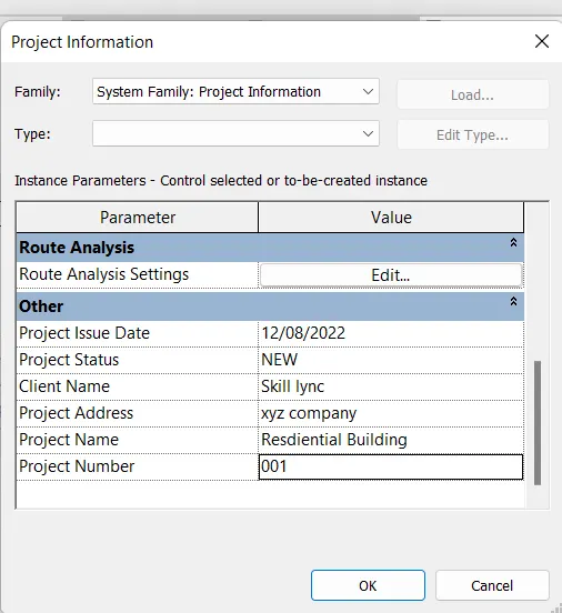
The last step is entering the project information details. For that under the manage tab select the project information option to open the project information dialogue box.
enter all the necessary project details and click ok to apply the changes.
4Q:
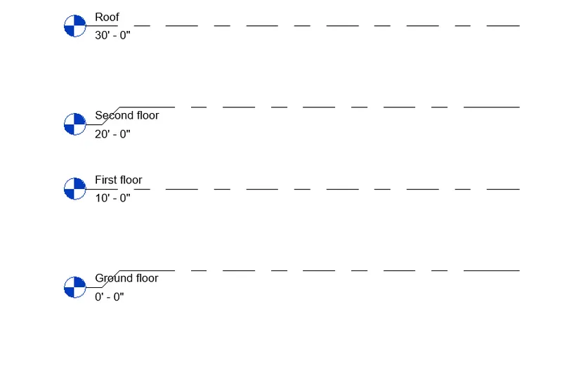
AIM: Understand the concept of Levels and Grids. Follow the naming and conventions. Create the following Levels: ( Convert to metric equivalents if metric is your units)
Ground Floor @ 0’
First Floor @ 10’
Second Floor @ 20’
Roof @ 30’
INTRODUCTION:
LEVELS:
Use the Level tool to define a vertical height or story within a building.
About Levels
Levels are finite horizontal planes that act as a reference for level-hosted elements, such as roofs, floors, and ceilings.
To Deleting Levels
When we delete a level, Revit also deletes associated views and model elements that are hosted by the level (for example: doors, furniture, and rooms).
Add Levels
In addition to creating a level for each story in a building, we can also create reference levels, such as sill level.
Change the Level Type
Change the level type on placement or change the type of an existing level in a view.
Edit Level Lines in a View
In an elevation view or a 3D view, we can change the size of level lines, change level names, and change the elevations of levels.
Move Levels
We can move a single level or multiple levels in elevations, sections, and 3D views.
Offset a Level Line from Its Bubble
When working with levels in elevation views and section views, we may want to offset a level label from its level line.
Level Type Properties
We can modify level type properties, such as Elevation Base and Line Weight, in the Type Properties dialog.
Level Instance Properties
Modify instance properties to specify the level's elevation, computation height, name, and more.
GRIDS:
We can Use the Grid tool to place column grid lines in the building design. We can then add columns along the column grid lines. Grid lines are finite planes. We can drag their extents in elevation views so that they do not intersect level lines. This allows us to determine whether grid lines appear in each new plan view that you create for a project. Grids can be straight lines, arcs or multi-segmented. You can hide grid lines after you add them.
Add Grids
Grids are annotation elements that help organize your design.
Change the Grid Type
Change the grid type during placement or change the type of existing grids in a view.
Change the Grid Value
Change the grid value directly in the grid header or in the Name instance property.
Offset a Grid Line from Its Bubble
There may be times when you sketch a grid line and want to offset its bubble from the rest of the grid line.
Show and Hide Grid Bubbles
You can control whether grid bubbles display at either end of a grid line.
Adjust the Centre Segment of a Grid Line
You can adjust the length of the gap or centre segment in an individual grid line.
About Customizing Grid Lines
Customize grid lines by modifying the Type Properties for the grid type.
Change a Continuous Grid Line
Change the line colour, weight, and pattern of the entire grid line.
Create a Grid Line with a Centre Gap
Hide the centre segment of the grid lines to create a gap.
Create a Grid Line with a Centre Segment
Display the centre segment of the grid line using a different line colour, weight, and pattern than the end segments.
Grid Type Properties
Modify grid lines, such as line style for the centre segment or the symbol used for the ends of the grid line, on the Type Properties dialog.
Grid Instance Properties
You can change properties for an individual grid line, such as the Name or Scope Box.
PROCEDURE:
Open a Revit file in architectural template.
In project browser under elevations select the East view.
2 levels are already present there just rename them to ground floor and first floor and change the height of level as needed.
Now in architectural tab select the grid option draw the second floor and roof at a distance of 20’ and 30’ respectively and name them.
GRID CREATION
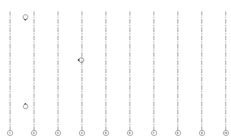
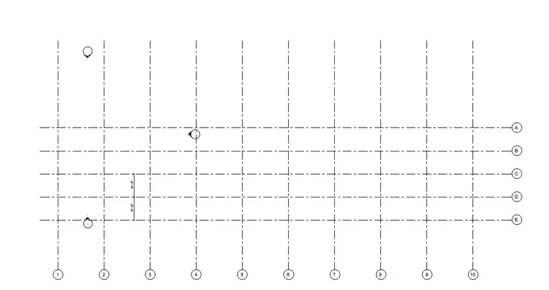
Longitudinal Grid lines was drawn 20’ apart from each other using the grip opton in the archetitectural tab from left to right and numbered from 1 to 10
Transverse grids was drawn next in the same manner as above and at a distance of 10” and named from A to E.
5Q:
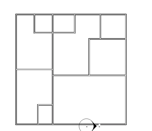
AIM: 3D modelling of residential unit – From looking at your house / or a place you aspire. Create a conceptual layout of the residential unit. You can measure using a tape or
you can access your residential plan to create a similar layout.
PROCEDURE:
Open the Revit application and create a new architectural template and save the project file.
Now enter the project information details
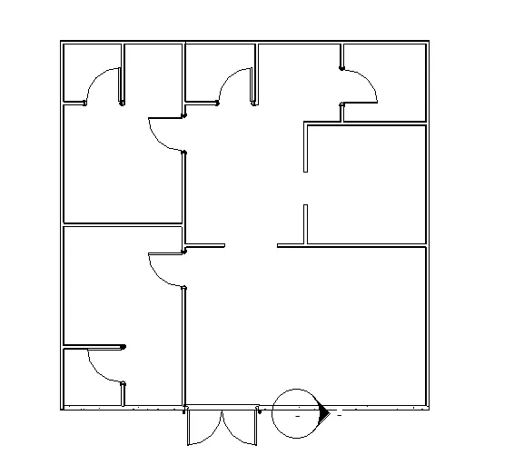
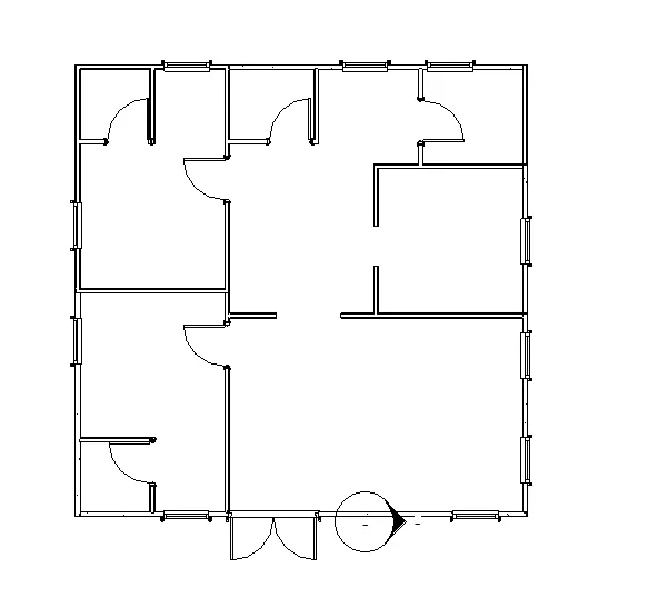
Now using the wall option under the architectural tab create the outline of the house
From the architectural tabs doors was placed at places necessary and opening was created as required.
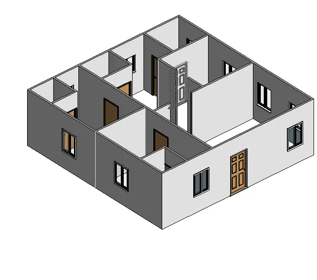
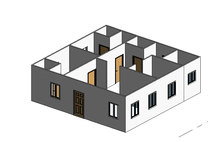
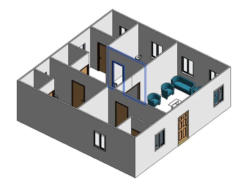
From the architectural tabs windows was placed at places necessary. The isometric 3D realistic view of the layout prepared.

6Q:
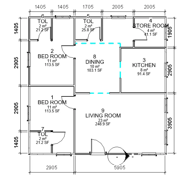
In the layout created draft the level of details you are planning to include – Dimensions of room, components you plan to add in the residential unit.
The layout which we have created is to be provided with dimensions.
In the annotation tab linear dimensioning was used to provide dimensions.
Now in the architectural tab click room followed by room tag.
7Q:
Identify the residential model elements such as Door, Windows, Tables, Chair, Couch, Bed, Lamps from the library and insert them to the model . Save the project for use
for Assignment 3
To identify the residential model elements from the library and insert them to the model
In the architectural tab select components > place components > load family > libraries > India
From this library select the required components and place it at positions necessary.
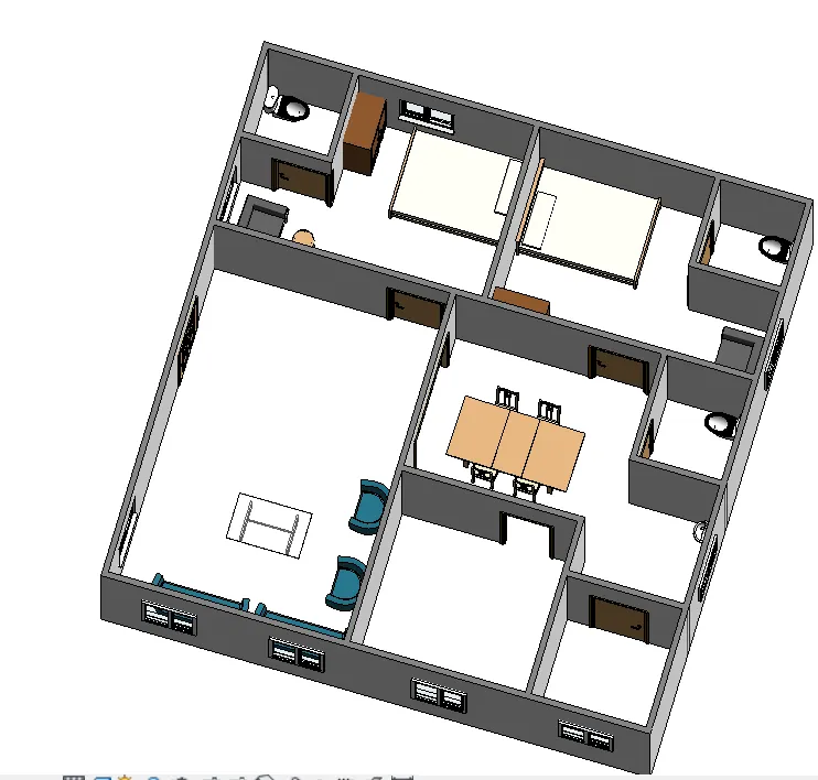
Counter tops with sink was placed in kitchen.
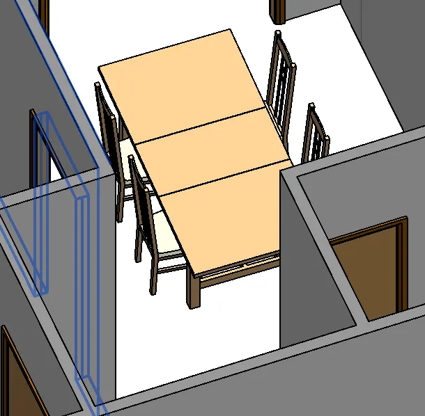
Dining table with chair in dining area.
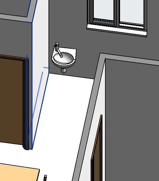
Washing machine and sink in the work area.
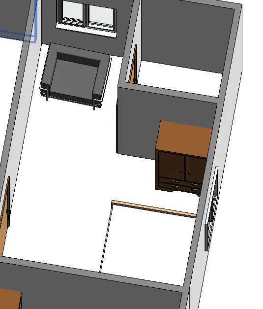
Bed and cabinet file 2 drawer was placed in bed rooms.
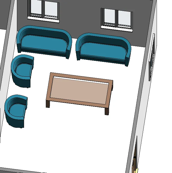
Coffee table, 2 seated sofa and entertainment centre was placed in hall.
Water closet in the toilet.
The complete drawing in 2d and 3d
Isometric View:
sink in the work area:
Bed and cabinet file 2 drawer was placed in bed rooms and Water closet in the toilet:
Coffee table, 6 seated sofa
Dining table with chair in dining area: