Creating Levels, Grids, Layout and model elements for a residential unit using REVIT
1) What is BIM? Summarize the features of BIM and benefits of using BIM over 2D CAD tools.
ans-
- BIM stands for building information modelling and it is workflow process. its based around models used for planning, design, construction and management of buildinding and infrastructure projects.
- Building information modelling (BIM) is a process of creating and managing information on construction project throughout its whole life cycle. as a part of this process, a coordinated digital description of every aspect of the built asset is developed, using a set of appropriate technology. this digital description includes a combination of information- rich 3d model and associated structure data such as product, execution and handover inforrmation.
features of BIM :
a) easy access to information -
it provides every minute detail of the project. every stakeholder makes their disciplines - specific input to make it a comprehensive shared information resource about the structure. one can easily acess the right information at the right time that provides a reliable basis for decision making during structures entire life cycle.
b) making the process more extensive-
BIM modeliing services providers, are allowed to work in five dimensions, time and cost being the additional dimensions. they are thus able to to produce accurate cost and material estimates and precise time schedule of the project even as the designed is being developed.
c) more comprehensive overview of the project -
BIM models not only present 3d geometric view of the structure, they provide more comprehensive overview of the entire building process. it covers every component of this process from geometrical aspect of the design to spatial relationship from light analysis to provision of various services, from topographical information to quantities and properrties of building components and so on.
d) lifelike views -
it allow you to obtain various views from building model and produce high quality accurate drawing. this view are based on single definition of each objects and thus gives more realistic and accurate idea of final structure.
benefits of using BIM OVER 2D CAD tools :
- BIM allows you to bring all your design, including CAD models into a single databse.
- BIM can expand on your basics CAD designs, providing more information to project stakeholders in the process.
- BIM can capture reality in a way that 2d cad drawings are unable to capture.
- a single BIM software can be used to design all the disciplines such as architecture, structure, and MEP
- a lot of labour and time is saved when deriving quantities from BIM model with the use of tool such as element counts, volumes, areas etc.
- synchronization between all the drawing such as plans, elevation, sections, perspective etc. is easier in BIM as all these drawings are extracted from single model.
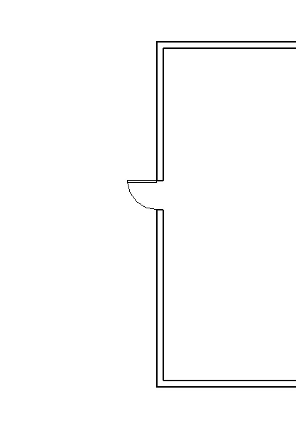
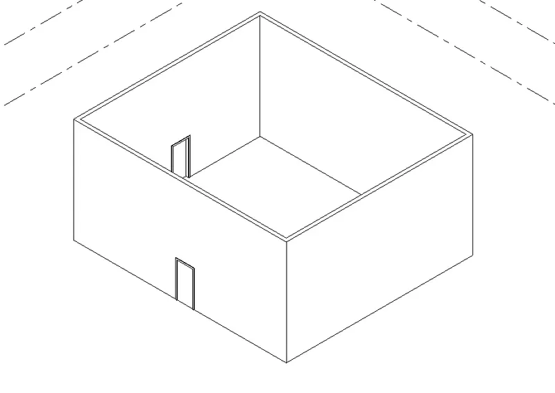
2) Understand the concept of Categories, Families, Elements, Instances in Revit. Go to Insert Tab, choose a category. Pick a family and element. Understand the instances and insert it to Revit model.
ans-
categories - a category controls the organization, visibility, graphical representations and scheduling options of families within project. for example doors, curtain walls, furniture and lighting fixtures etc.
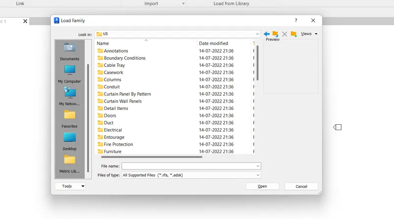
family - a family is a grouping of 2d and 3d information that serves to represent a discrete building or documentation element in the project. it defines parametric, graphical and documentation equirements. all of the element use in revit are families. you cant create anything in revit without using families.
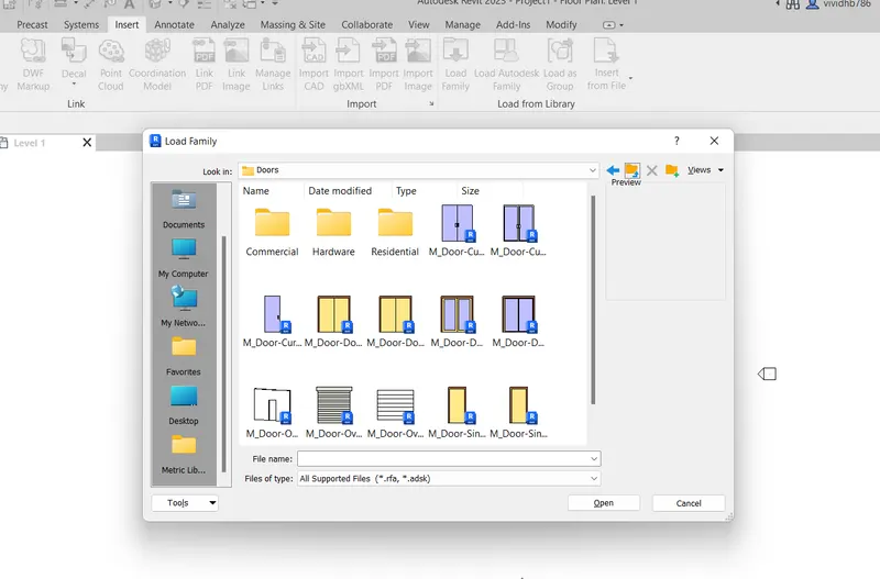
elements - elements are building blocks of 3d model. they represent the real world components that a designer adds to the model. some elements such as wall, windows and beams are 3d and appear in all views. you can think of these element as components that exist in building. 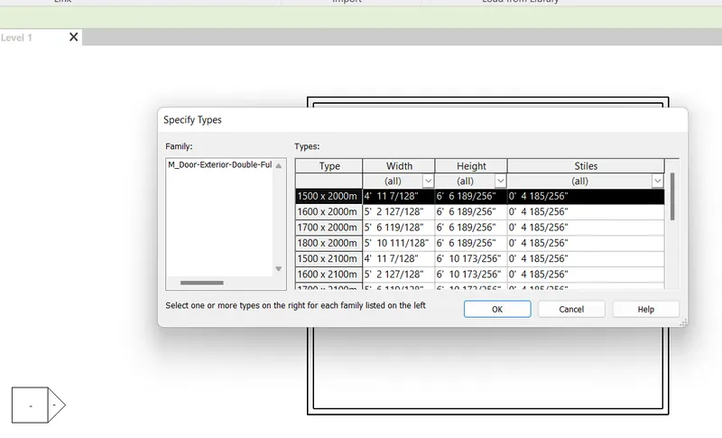
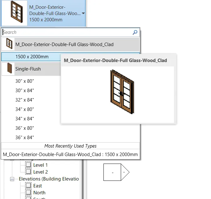
instance - an instance is an individual representation of a type in the project defined by unique parameteric, graphical and documentation charectrstics which makes it unique from other instances in project. e.g singlw wall or single door or any other single element. single element attach to the wall.
3) Setting up a Project – Open a project file with architectural template. Save the file with appropriate name. Set up the project units to Imperial / Metric based on your convenience of modelling. Complete the project information under Manage tab. Set up the maximum backups for project file to 3
AIM : setting up a project in revit with architectural template, save with appropriate name, setup units, complete project information and setup maximum backups.
INTRODUCTION :
in this project we have opened project with architectural template. we have saved the file with name. we have setup units into imperial. we have completed project information and setup maximum backups
PROCEDURE :
step-1 :
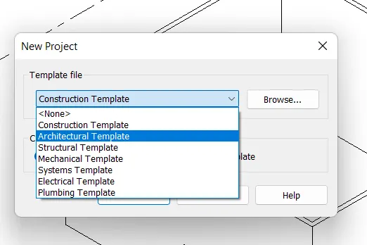
- open revit > select new > select the architectural template
OR
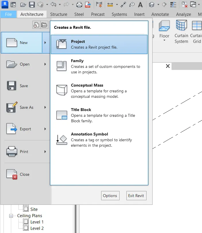
- if you have already opened file >go to file tool bar > select new > select project .> press ok
step-2 :
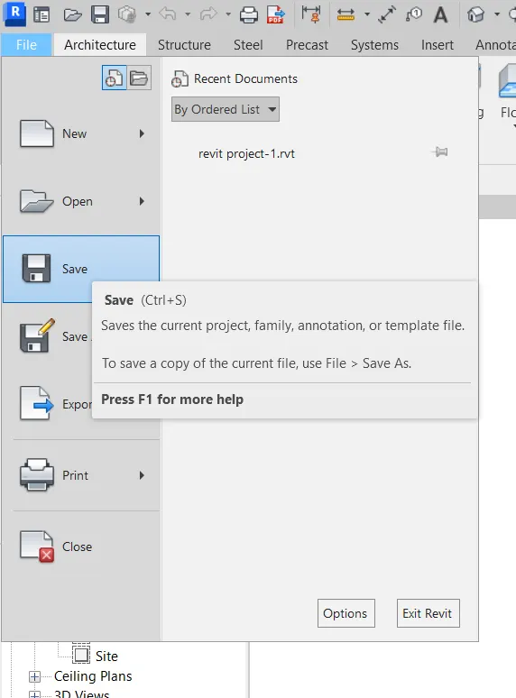
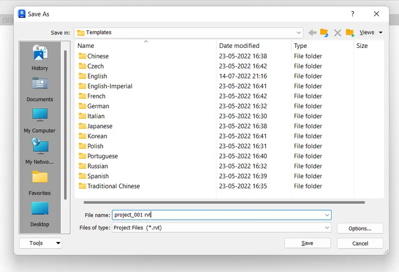
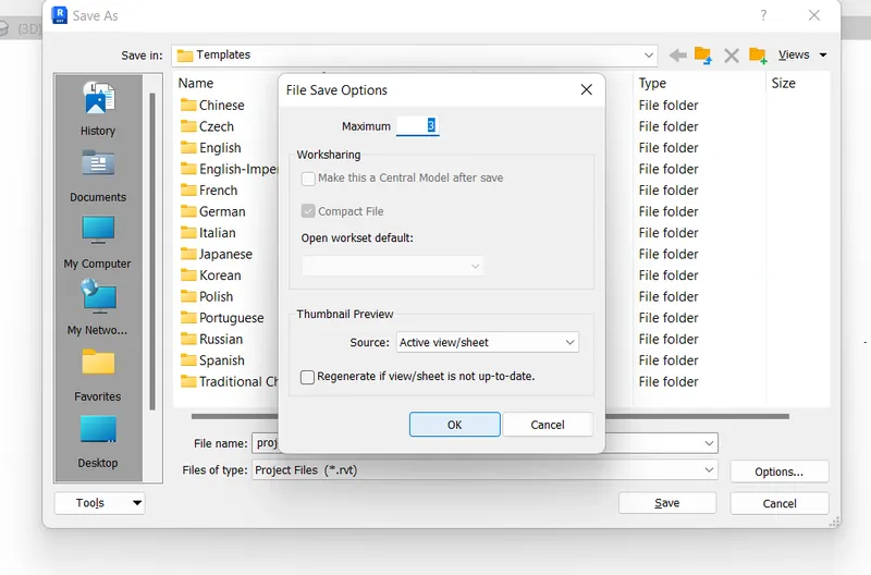
go to file menu > select save > write the file name > select option > set max save 3
step-4 :
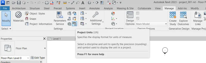
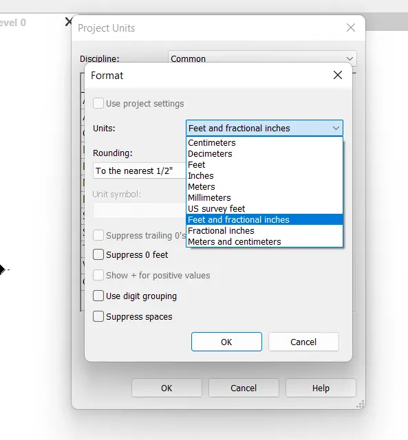
go to manage tab > select project units > set the unit in feet and fractional inches
step-5 :
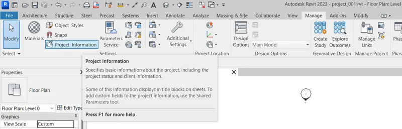
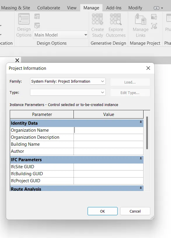
go to manage tab > select project information > fill the details of the project
RESULT :
we have completed project in revit with architectural template, saved with appropriate name, setup units, completed project information and setup maximum backups.
4.
AIM :
Follow the naming and conventions. Create the following Levels: ( Convert to metric equivalents if metric is your units)
Ground Floor @ 0’
First Floor @ 10’
Second Floor @ 20’
Roof @ 30’
Grids Transverse Grids A, B,C,D, E @ 10’ spacing
Longitudinal Grids from 1 to 10 @ 20’ spacing
INTRODUCTION : in this project we have understood the concepts of levels and grids
PROCEDURE :
STEP-1-
- open revit > architectural template
- set unit to feet and inches
- go to project browser > select elevation > select east
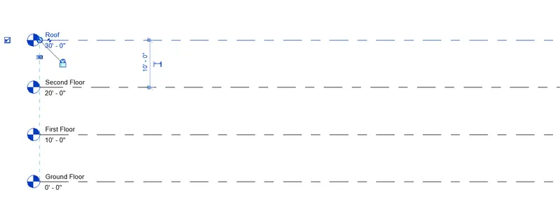
- go to architecture > select levels > draw a 4 levels at a distance of 0,10,20,30
- name the level as ground floor, first floor, second floor, roof
STEP-2-
- go to project browser > select floor plans > select floor
- go to architecture tab > select grid > draw horizontal grid
- select grid > set offset 10' > draw 4 offfset
- click on the text name the grid as A,B,C,D,E
- go to architecture tab > select grid > draw vertical grid
- select grid > set offset 20' > draw 9 offfset
- click on the text name the grid as 1,2,3,4,5,6,7,8,9,10.
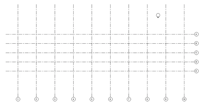
RESULT :
we have understood concept of grid and levels. we have created the figure as per given.
5) 3D modelling of residential unit – From looking at your house / or a place you aspire. Create a conceptual layout of the residential unit. You can measure using a tape or
you can access your residential plan to create a similar layout.
AIM : Create a conceptual layout of the residential unit.
INTRODUCTION :
We have created a layout plan for our house and we have accessed our residential plan to create si lia layout.
PROCEDURE :
- first we have drawn a residential plan layout with standard dimensions
- use wall architectural to create walls
- we convereted into shaded visual style
- we have provided dimension to layout
- go to annotate > select aligned > select wall faces > give the dimensions
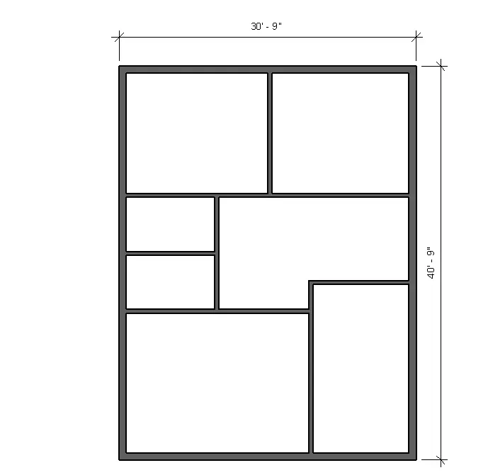
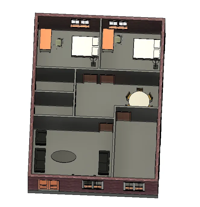
- 3d view of residential plan layout .
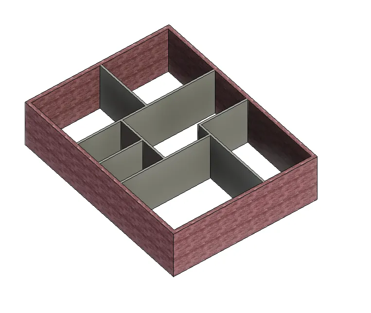
RESULT :
We have created conceptual layout of the residential unit
6) In the layout created draft the level of details you are planning to include – Dimensions of room, components you plan to add in the residential unit
AIM :
In the layout created draft the level of details you are planning to include – Dimensions of room, components you plan to add in the residential unit
INTRODUCTION:
we have added different components in plan and provided dimensions to rooms.
PROCEDURE :
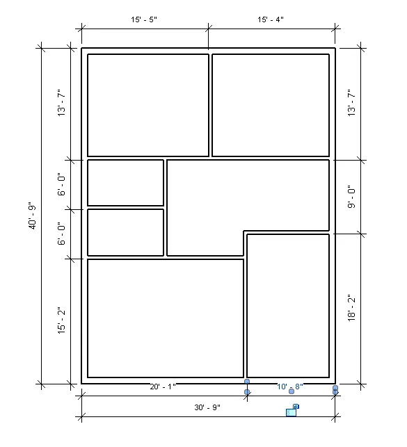
step-1 -
- previously drawn residential plan we have provided dimensions randomly
- go to annotate > select aligned> select wall faces > give dimensions
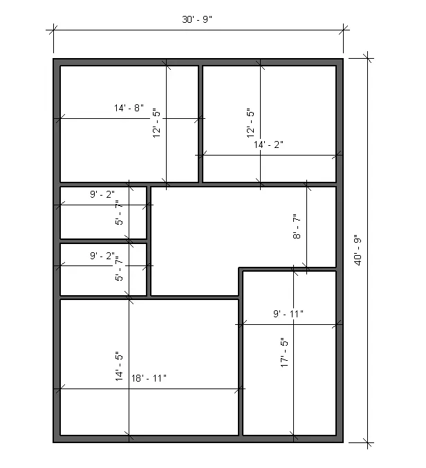
step-2-
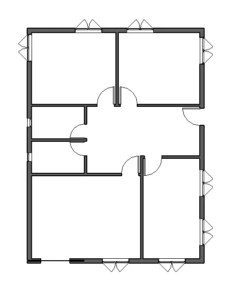
- we have provided doors and windows components to building plan
- go to insert > go to librarires > go to doors > select doors > select dimensions > paste in drawings
- go to insert > go to librarires > go to doors > select windows > select dimensions > paste in drawings
step-3 -
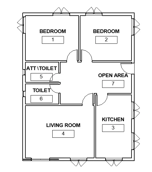
- naming the rooms
- go to architecture tab > select room option > select rooms to name
step-4 -
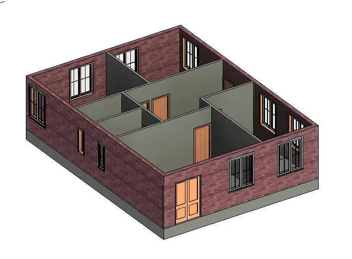
- providing plinth to building
- go to architeture > select floor architectural > draw plinth > give thickness of plinth
RESULT :
we have drafted the level of details – we have provided Dimensions of room, components added in the residential unit
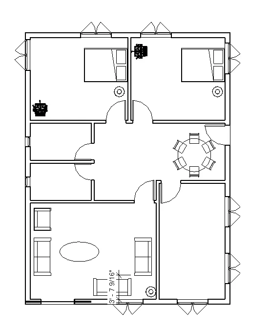
7.Identify the residential model elements such as Door, Windows, Tables, Chair, Couch, Bed, Lamps from the library and insert them to the model . Save the project for use for Assignment 3
AIM :
Identify the residential model elements such as Door, Windows, Tables, Chair, Couch, Bed, Lamps from the library and insert them to the model . Save the project for use for Assignment 3.
INTRODUCTION:
in this project we have added elements in residential model and saved it
PROCEDURE :
- open previous plan
- go to insert > select load family > select different elements and load it in drawings
- go to architecture > go to component > go to place component > select component to install
- doors and window
- tables, chair, couch, bed, lamps
- finally saved the project
RESULT :
we have Identified the residential model elements such as Door, Windows, Tables, Chair, Couch, Bed, Lamps from the library and insert them to the model . Save the project for use for Assignment 3.