Creating Levels, Grids, Layout and model elements for a residential unit using REVIT
1. Rivet platform for the Building information and modeling is the design and documentation system that supports the design,drawings,schedules etc.Rivet building elements are
- View elements
- Model elements
- Annotate elements
BIM is a process of creating and managing the data of a building asset. It enables and develop multi disciplinaroy details for the digital representation of the structure throught its life time from planning,design and construction BIM is visual representation of the charecteristics of the building unit from the inception onwards.It helps to share the reprosity of the collabrative information through out the life time.It mainly contains the 3d elements of the model and this autodesk technology helps to access the project by the contactors, designers, architects. BIM helps to create the virtual model of the building or to share the model between the various engineers like struture,Electrical,Plumbing etc.
Features of the BIM are:
- Access of the information:The informtion in the building asset can be easily accessed and if we require any changes can be easily applied to the building asset with out any undulations.
- To make the process more expressive:CAD software helps to work in 3 dimensional i.e length,width and height where as the BIM allows you to work in 5 dimensional i.e Time and cost including the length,width,height.The asset is designed or analyzed with the more stipulated time and we can express the every minute details of the building unit.
- Comprehensive view of the project:In BIM the building is designed or developed by considering the every minute details and analyzing the building by viewing to its interior considerations also.It also helps to know the quantities and to know about the tropographical features of the project.
Benefits of the BIM:
- Complete representation:In BIM the complete representation of the building asset with all the details is developed.It also represents the electrical and HSV representation is done with the BIM.
- Instant updates:In BIM the updates can be modified instantly with out any delay or deviations.
- Time constraint:BIM helps to prefabricate the structure units and it stimulate the time factor.
- Resource tracking:BIM helps to find the qunatities by the time of planning and it helps to track the resources for the project with out any delay.
2.Categories:
- Category is one of the rivet element and it controls the organisation, visibility,graphical representation and scheduling the options and families with in the project.
Family:
- Family is the group of 2d or 3d information that represents the discrete building unit or documentation in the project. Family defnes the parametric, graphical and documentation requirement also.
Type:
- Once entering in to the family we can find the type option.Type is a specific representation of the element in the family defined by distant parametric,Graphical and documentation which makes unique representation from the other types in the family.
Instance:
- Instance is an individual representation of the type defined by distant parametric,graphical,documetation of the building unit.
Procedure:
- The families or the elements in the family group contains all types of doors,windows,and all types of furnitures like Chairs,tables,beds and lamps etc.
- They can be inserted according to the requirement and the necessity of the client or the residents in the building.
- The elements can be inserted individually and according to the required size.
- Click on the Component or click on the door or window on the architectural and clck on the load family option and it select the US folder and it contains the family groups residential commercial etc and select the folder which we require either residential or commercial.
- After selecting the folder it contains all types of folders named with furniture,Doors,windows,Fire protection,conduit etc and select the element which we need to add in the model.
- After selecting the element we can also add the edit the size of the element and click on ok then the element with the required size can be inserted in the model in the window.
- The element can be changed to our comfort at any time.
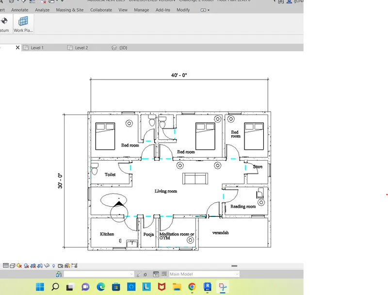
- The below unit inserted with doors and windows of door size M door single panel 900x2100 and M door single panel of size 750x2100.
- The elements inserted model obtained is shown as below.
3. Aim: To create the file with the architectural template and make it as aproject and create the back up files of the project with the rivet soft ware.
- In the rivet software the file is to be created with the architectural or constructional template and it should be saved as a project and the file is to be created with the back up files for the future reference.
Procedure:
- Click on the new option and select the required template architectural or construction and click on OK then the file with the required template is formed.
- Now click on the file option on the top and select save as option and select the project option and change the name of the file and we can name the desired title of the file and click on ok then the file is created as a project.
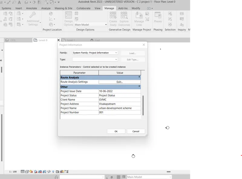
- After creating as a project the file the project information is inserted in the file using the manage option. Click on the Manage option in the ribbon then select the project information option and eneter the project title, organisation name,Project issue date and address of the project and click on ok.Then th project is saved for the future refernece.
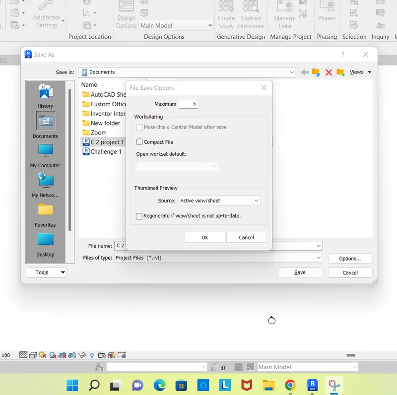
- Now the back up files are created for the project for the future reference,Click on the file option and select the save as option in the select the project then we can see the options icon and select the options icon and now the back up files are numbered as we require and click on ok option then the backup files are created. Maximum 99 number of back up files are created for a project file.
- The created project and the back up files are in form of shown below.
4. Aim: To create the levels and the grid lines of the project in the rivet soft ware.
- The levels are the height of the building with referenece to the natural ground level or fixed ground level we can plot the model with reference to the natural ground level and if the ground level is irregular then we can fix the particular level with repect to the mean sea level and we can plot the model with reference to the fixed ground level.
- The level in the various stages gives us the clear view and clear height of the building or any other unit.
- The level in the building is more mportant that the level fixed at a particular point is fixed with specified name i.e Plinth beam level,floor level,Roof beam level and slab level etc.
- The grid is set of lines plotted in the building model which gives the place and positin of the columns, beams etc. The grid is more important because when the columns are not linear then ar placed according to the grid position and using the grid columns, beams or the walls are placed very easily with out any undulations while plotting the building model.
Procedure:
- Click on the new option and select the required template architectural or construction and click on OK then the file with the required template is formed.
- The level can be plotted only in the elevation view and it couldnot be plotted in the other plans it shows the level difference in the plan or top view of the building unit.
- The grid can be plotted in any of the model and it can be used in the plotting the plan of the building.
- To create the level click on the elevation in the project browser in the right of the window and it displays east,west,north and the south side view of the building model and select the desired elevation view of the building model which may be east,west,north,south.
- Click on the architecture option in the ribbon and it shows the level and grid option in the left of the ribbon and select level option.The level option is displayed only it is in the elevation view where as the grid option is displayed in all kinds of the views.
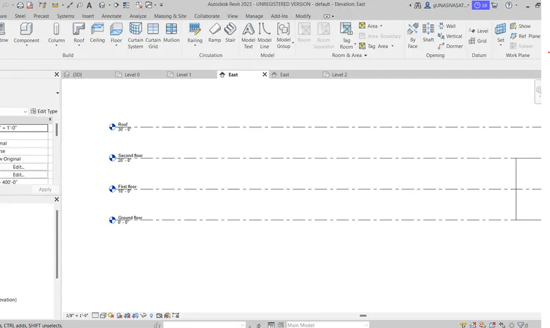
- Click on the level and select the pick line option and enter the level height as 10',15',20' and click on the window then the level line is plotted by displaying with the heigh of the lvel line.
- The height can be edited in the window itself by selecting the level line and the required height of the level line is entered and press enter.
- The grid can be plotted in any of the plan and elevation views of the building unit the grid can be plotted by selecting the architectural option in the ribbon.
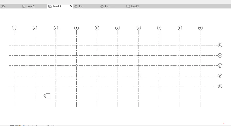
- Click on the architectural option and we can able to see the grid option then click on the grid option and selcet the pick line option and edit the grid distance and the grid line is plotted.
- Generally the grid lines are plotted in the longitudinal and in transverse direction.The grid lines are named with A,B,C,D,E etc in one direction and 1,2,3,4 etc with the other directions.
- The Formed level and grid lines in the rivet is shown as below.
5.Aim: To create the layout of the residential building using the rivet.
- The lay out is nothing but the size of the plot or the size of the site with a proper and fixed boundaries.
- A lay out is to be formed in a particular polygonal shape, The shape of the lay out shouldnot be irregular.
- In the lay out area the building or any other structure is developed.
Procedure:
- Click on the new option and select the required template architectural or construction and click on OK then the file with the required template is formed.
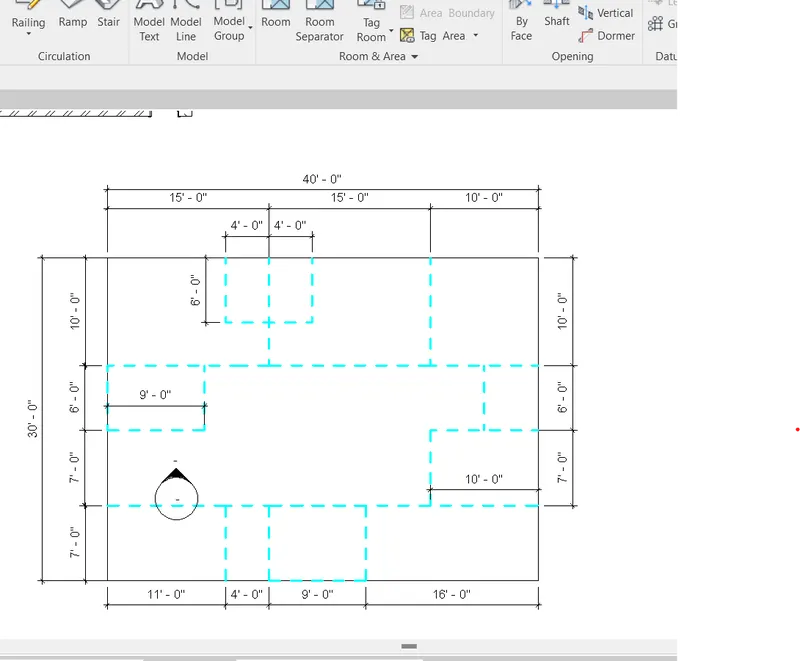
- To create the lay out of the building select the floor option in the ribbon and select the boundry line and plot the size of the lay out in the rectangular shape to a size of 40'x30'.
- The lay out is created with also the polygonal options if the layout is the shape other than the rectangle or square.
- The lay out with the fixed length and the fixed width is formed and now the lay out is divided in to the rooms or the chambers using the room separator option.
- As the lay out is formed to develop the residential building,so the layout is divided in to the various roms with the various sizes.
- Click on the room separator option in the ribbon and the layout is divided in to three bed rooms of size 2 nos 15'x10' andd 1 no 10'x10'.
- Click on the room separator and form the toilets of size 4'x6' in the rooms of size 15'x10'.Now form the rooms in the other side of the lay out and the roos should be consisted of kitchen 11'x7', pooja 4'x7', GYM 9'x7'.The rest of the space beside the gym is to be used for the verandah.
- Now the centre space is divided in to living room,Dining7'x9' and 6'x9' common toilet from the left and from the rightside of the lay out reading room 10'x7' for the children and the sotre 6'x5' is formed.
- The lay out is divided according to the vastu sahtra rules and regulations other wise there will be chance of formation of the negative energy in the residential building.
- The formed lay out of the building is shown in the below.
6. Aim: To convert the layout of the residential building in to the plan of the residential building in the rivet soft ware.
- The plan is slightly different from the layout but it reflects the details of the layout. The lay out is converted in to the plan by adding the wall thickness and the plotting the projections present any for the building unit.
- The plan is nothing but the top view of the building.The paln should be plotted and it gives the main important out look information required for the building to start the execution work in the site.
- The paln consists of the dimensions of the room in the desired unit system
Procedure:
- Click on the new option and select the required template architectural or construction and click on OK then the file with the required template is formed.
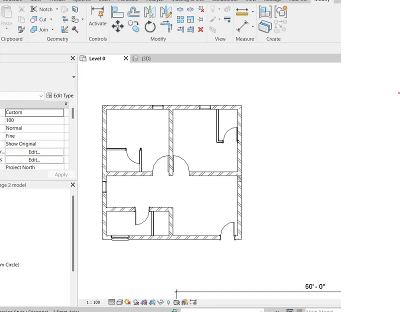
- To create the lay out of the building select the floor option in the ribbon and select the boundry line and plot the size of the lay out in the rectangular shape to a size of 40'x30'. The lay out is now divided in to the rooms and it is now converted in to the plan of the building.
- The lay out is converted in to the plan by adding the wall thickness, click on the architecture option in the ribbon and select the wall option in the building the properties bar with various types of the wall is opened in the left side of the window.Now select the appropraite wall which may be concrete,brick or made of any other materials then the wall is now selected and the click on the edit type and edit the strutural details that is thickness of the wall and apply the requiredd thickness of the wall.
- Now change the location constraint of the wall which may br the finish exterior,finish interior,core exterior,interior and the wall center line in which the wall is fixed and when we change the wall thickness the update is occured by keeping the location constarint constant.
- Click on the wall and select the and click on the edit type and update the wall thickness as 8" in the structure edit and click on the apply option then the wall with the 8" is updated
- The wall is plotted from the one of the corners of the layout of the residential building and the wall are developed to the end of the rooms.
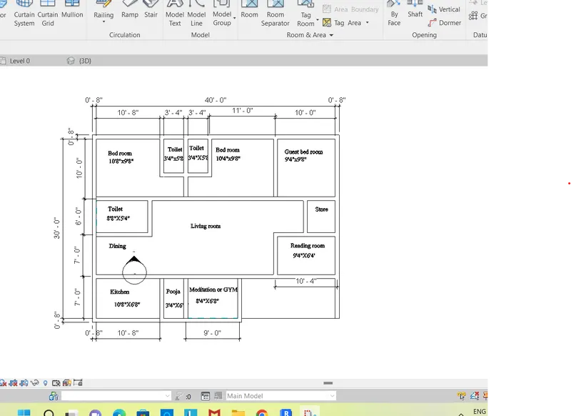
- The wall thickness mary from the main wall and the partition wall of the building but in the below plan the wall thickness is same for all the walls and is equal to 8".
- So the select the same wall option again and plot the walls of the building. If we require any change or update of the walls we can also update them after the plotting also.
- Now For the plan dimensions are inserted using the annotate option in the ribbon in the window .Click on the annotate option in the ribbon and select the linear option and the dimensioning is plotted for all the rooms.
- After the completion of the dimensioning of the walls, the rooms are titled with their appropraite names using the model text option in the ribbon bar.By clicking the model text option the rooms and the sizes are texted and click on the Ok option and they are placed in the respective rooms in the plan.
- Now the layout is converted in to the plan and the plan obtained is shown below.
7.Aim: To insert the residential model elements of the building from the libraries in the rivet software.
- The plan gives the basic information for the building which is needed to start the execution work of the building and the plan should also include the interior elements of the building.
- The plan should be inserted with the various elements like Furniture,electrical and plumbing which will fulfill the daily needs of the inmates in the building.
- The plan should also contains the details of doors and windows of the building and these all inserted and they the interior execution is done according tothe sizes mentioned in the plan.
Procedure:
- Click on the new option and select the required template architectural or construction and click on OK then the file with the required template is formed.
- After plotting the plan the elements of electrical,plumbing,furniture from the libraries are inserted in the plan to ful fill the requirements.
- The elements are inserted with the insert option in the ribbon,Click on the ribbon optin and select the load family and it will take you in to the folder US in which all kinds of families regarding annotations furniture, electrical, plumbing, structural, fire fighting and the other units elements are present in the folder wise.
- Click on the insert option and select the load family and select the us folder and select the doors options and it contains the various types of doors and select the doors which we require and edit the size of door if we require and insert the door for all the bed rooms as the doors provide the access and ventilation in to the building.The doors of the bed room and the doors of the toilet should be different as the toilet should not require the large size door.
- After the insertion of the door windows are inserted for the building in the same manner for every room there should be atleast one number of the window.
- Now the building inserted with the furniture click on the insert option and select the furniture family in the us folder and selct the beds and insert the beds in the bed rooms, sofa set in the living room, seater in the reading room,and dining table in the dining area.
- Now click on the Light ing family in the us folder and insert the lights in every bed room and well as in the kitchen and the toilets also.
- Now click on the plumbing family in the us floder and sekect the water closets and insert the water closet in the toilets and insert single sink in the kitchen.
- The elements can be modified after the insertionalso according to the inmates requirements the size of the elements acn be updated to the required size and shape.
- The final model of the residential building with all kinds of the elements inserted is formed as shown in the below.