Creating Levels, Grids, Layout and model elements for a residential unit using REVIT
1. BUILDING INFORMATION MODELING:
BIM is a process for creating and managing information on a construction project throughout its whole life cycle. As part of this process, a coordinated digital description of every aspect of the built asset is developed, using a set of appropriate technology. It is likely that this digital description includes a combination of information-rich 3D models and associated structured data such as product, execution and handover information.
In the early stages of a BIM project, a collaborative team is assembled. It agrees the process and information structures to ensure that the design information developed is coordinated, and will be of maximum benefit to those involved in the construction and operation stages. Involvement of those that will be involved at a later stage of the project (such as manufacturers or the client’s FM team) can greatly help with this initiation.
As the project enters the construction stage, the information developed can be used to plan and build more efficiently. Where revisions to the design are required, any changes can follow the agreed process in a transparent and recorded way.
Finally, as the construction project is completed and the in-use stage commences, the information that has been modelled can be used to operate the built asset. Real-time information about the asset’s performance is modelled so that certain aspects of the built asset have a ‘digital twin’ equivalent.
FEATURES OF BIM:
- Centralize document management
- Design and visualize a 3D model
- Create automated reports on all workflows
- Manage and track resources
- Monitor and manage construction costs
- Detect and resolve clashes
BENIFITS OF USING BIM OVER 2D CAD
BIM allows to integrate useful information within the model at every stage of the design process, from the architectural to the executive, (structures, systems, safety, energy performance, etc.) and management (metric calculations, suppliers chain, maintenance etc.).
BIM is a collaborative and integration-based design method; the different actors involved can enrich the information model, insert, extract, update or modify information.
CAD and BIM are different mainly because BIM is a collaborative design environment.
CAD, or Computer-Aided Design, which allows the processing of a project through 2D and 3D drawings, it is limited to the design of simple graphic elements (lines, circles, arcs). It is not a collaborative method, although it allows the sharing of information through the exchange of drawings and diagrams.
BIM, on the other hand, is not limited to rendering, but specifies the performance and functions of each object.
Thanks to the BIM it is possible to recreate a virtual model of the building which is not only a three-dimensional representation, but a dynamic environment that contains a series of information on geometry, materials, load-bearing structures, systems, costs, safety, etc.
2. We select the catagories, families, elements, instances by selecting the load family in the insert toolbar
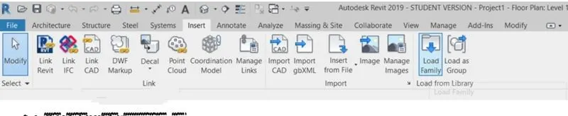
Category: A Category controls the organization,visibility, graphical representations, and scheduling options of families within the project.
Families are grouped and sorted by catagory in the content libraries and in the project browser
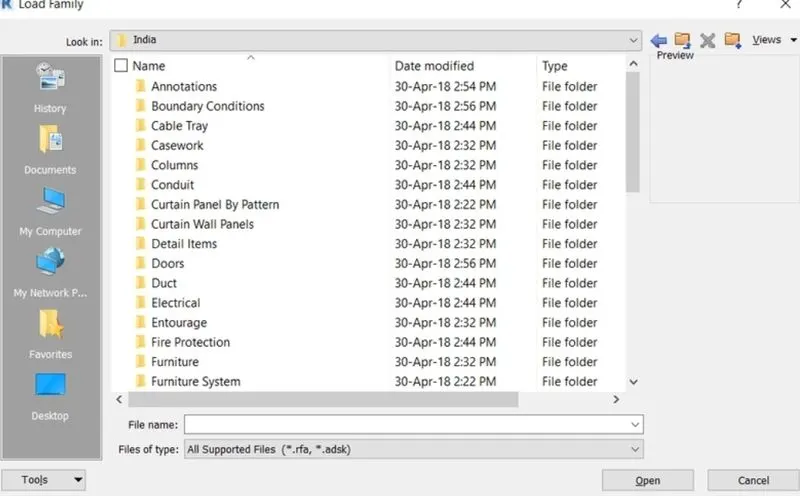
Family: A Family is a grouping of 2D and/or 3D information that serves to represent a discrete building or documentation element in the project. It defines parametric, graphical, and documentation requirements.
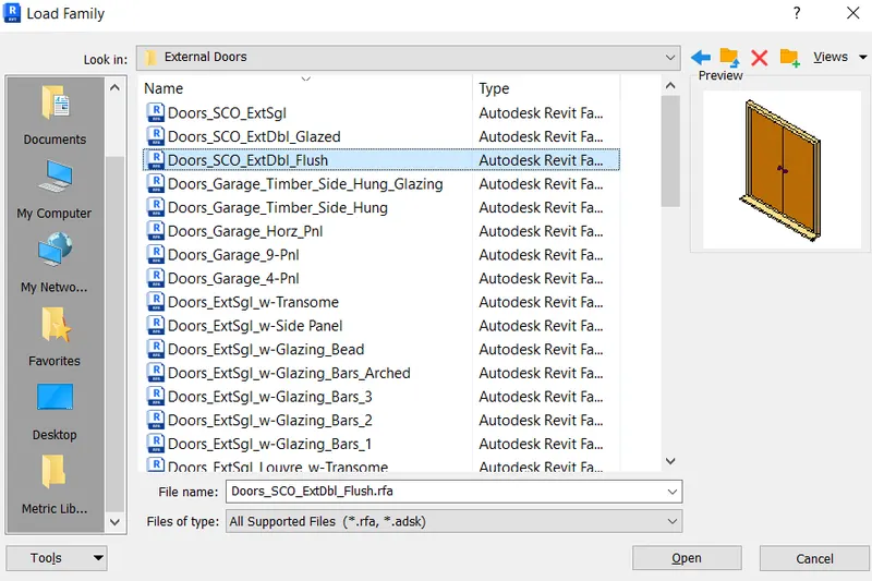
Elements: Everything in Revit is an Element.Elements are classified into a Model, Datum, or View-Specific class. Model elements are further classified into Hosts & Components and, View-Specific are further classified into Annotations & Detail Items.
Model Elements: These are the three-dimensional elements in Revit that are visible in all 2D and 3D model views.
• Hosts: These are the model elements that typically represent building elements which are
constructed onsite. They can host Component elements.
• Components: These are the model elements that typically manufactured building elements
which are installed onsite. They can be hosted by Host elements.
Annotation Elements: These are the two-dimensional elements in Revit that are specific to the 2D view in which they are placed. Some can appear in 3D model views.
• Annotations: These are documentation elements that enhance a view with construction
information.
• Detail Items: These are documentation elements that can overlay the Model elements or standalone to describe the finite constructions.
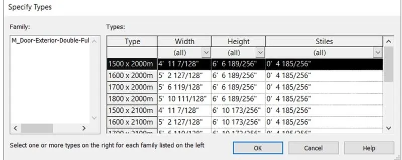
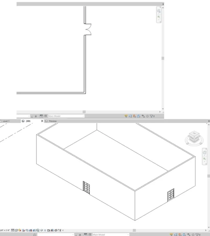
Instance: An Instance is an individual representation of a type in the Project defined by unique parametric, graphical, anddocumentation characteristics which makes it unique from other Instances in the project
3. AIM:
Setting up a project in the revit software
INTRODUCTION:
For settting a project we need to select the architectural template for modelling thearchitecture plan
When we save the file with appropriate name,the name will be saved in a particular folder
The project units toolbar is used to set the project unit that applies to the whole project
The project information option is used to save the information of the project by entering the project name,prroject issue date, project status , project status, project address etc
PROCEDURE
STEP 1:
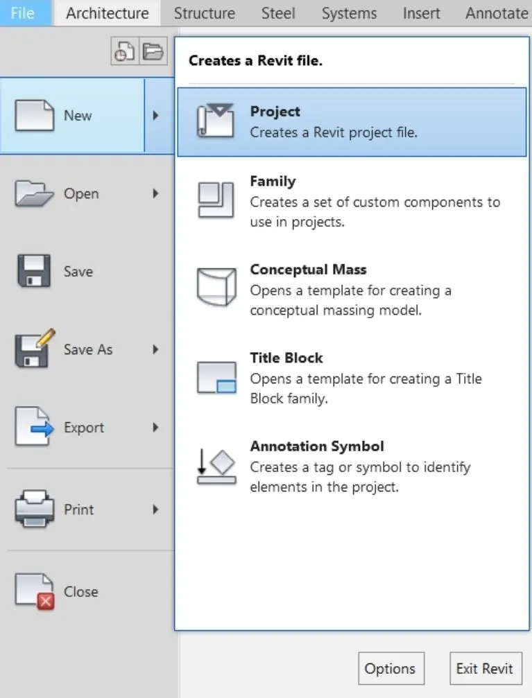
First select the file toolbar,then the new tab appears and select the new option and then select the project
STEP 2:
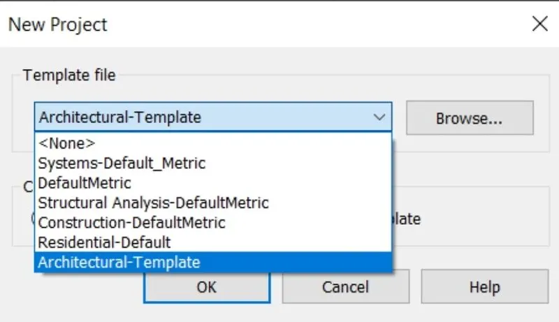
Next select the architectural template in the new project tab
Click ok
STEP 3
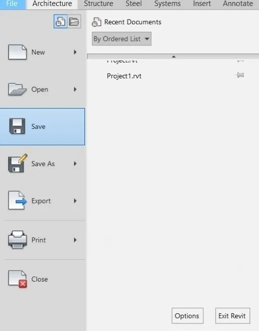
After the project is done open the file toolbar and select the save option
After selecting the save option the new tab will be visible
Enter the new name and before saving the name of the project
Click on the options at right corner of the save as tab as shown in the screenshot below
STEP 4:
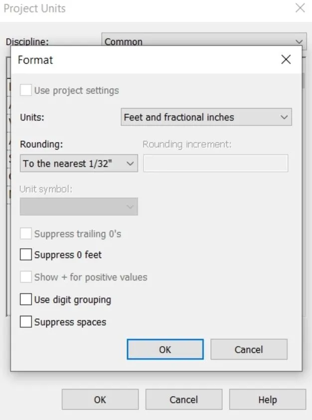
Next we need to select the project nits in the manage toolbar
Next put the units to feet and fractional inches as shown below
STEP 5:
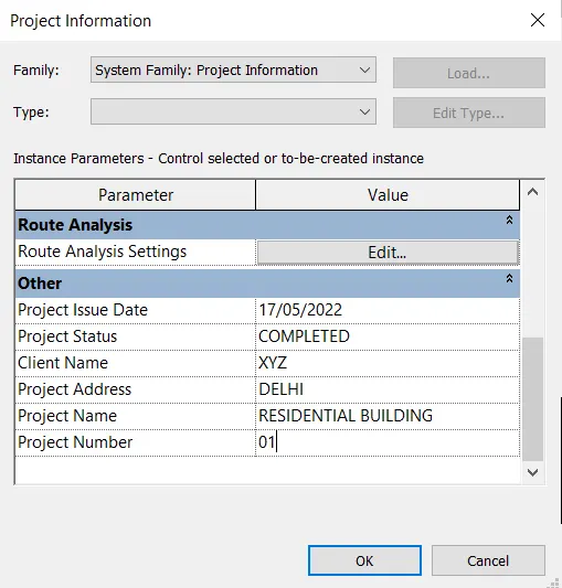
Next we open the manage toolbar and the select the project information
After selecting the project information,the new tab will be visible then enter the project dtails in the project informatio tab as shown below in the screenshot
RESULT
Setting up a project is done sucessfully in the revit in detailed manner
4. AIM:
To create the gris and levels using the given details
INTRODUCTION:
Levels establish a framework for the model. All elements in the model are assigned and constrained to levels in order to establish their position in 3D space. Levels are used to create the plan views of a model, which facilitate modeling and navigating in the model.In addition to creating a level for each story in a building, you can also create reference levels, such as sill level. Open the section or elevation view to add levels to. On the ribbon, click (Level). Architecture tab Datum panel (Level) Structure tab Datum panel
Open the Visibility/Graphic Overrides dialog
Click View tab Graphics panel (Visibility/Graphics), or use the keyboard shortcut v g.
Click the Annotation Categories tab.
In the Visibility column for Levels, select the check box to show levels in the view
Clear the check box to hide them
Revit Levels and Grids are really the skeleton of building projects. Typically Levels in Revit are used to indicate the locations of floors, foundations, and the roof of a building in section and elevation views. More recent versions of Revit include Levels in 3D views. Grids are used to host columns and walls.
Grids are annotation elements that help organize your design. Its a tool that allows you to line up model elements in the same location across multiple sheets. It does this by allowing you to move the viewport on a sheet by snapping to the datum elements in your model (levels, column grids and reference planes) and then snapping them to the intersections on the Guide Grid.
- On the ribbon, click Grid.
- Architecture tab>Datum panel> Grid
- Structure tab>Datum panel>Grid
- Click when the grid is the correct length.
PROCEDURE:
STEP 1:
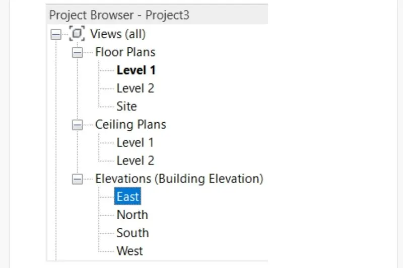
For creating the levels first we select the levels in the project browse
STEP 2:
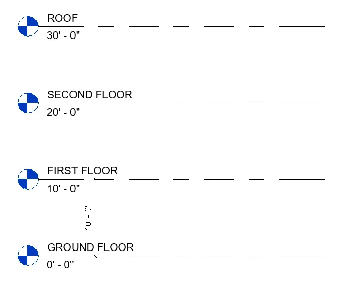
Next the levels will be displayed on the screen as shown below
STEP 3:
Next we draw the grid lines horizontaly indicating the grids with A,B,C,D,E
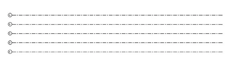
STEP 4:
Next we draw the vertical grid lines on the horizontal grids,indicating the grids with numbers from 1 to 10
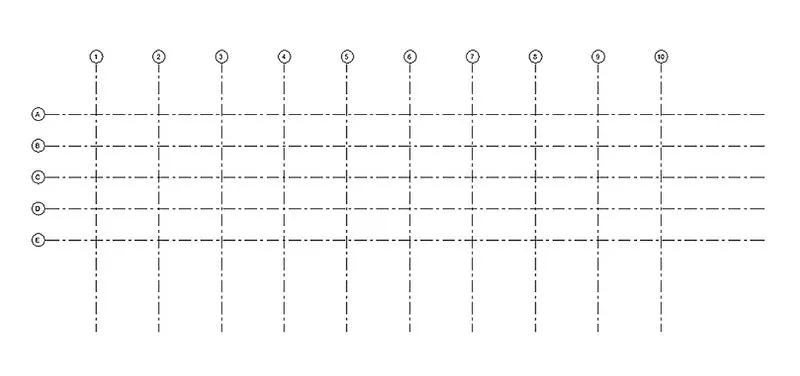
RESULT
The levels and the grid lines are drawn sucessfully in the revit in detailed manner
5. AIM:
To create a conceptual layout of the residential unit in the revit
INTRODUCTION:
3D modeling is the process of developing a mathematical coordinate-based representation of any surface of an object in three dimensions via specialized software by manipulating edges, vertices, and polygons in a simulated 3D space.
Three-dimensional (3D) models represent a physical body using a collection of points in 3D space, connected by various geometric entities such as triangles, lines, curved surfaces, etc.
Being a collection of data (points and other information), 3D models can be created manually, algorithmically (procedural modeling), or by scanning.
PROCEDURE:
STEP 1:
First we draw the residential layout with the standard dimensions as shown in the below figure
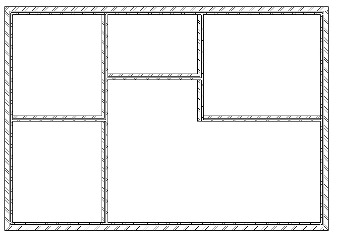
STEP 2:
Next we change the visibility of layout as shaded as shown in the figure
Next add dimensions to the layout plan, shown below
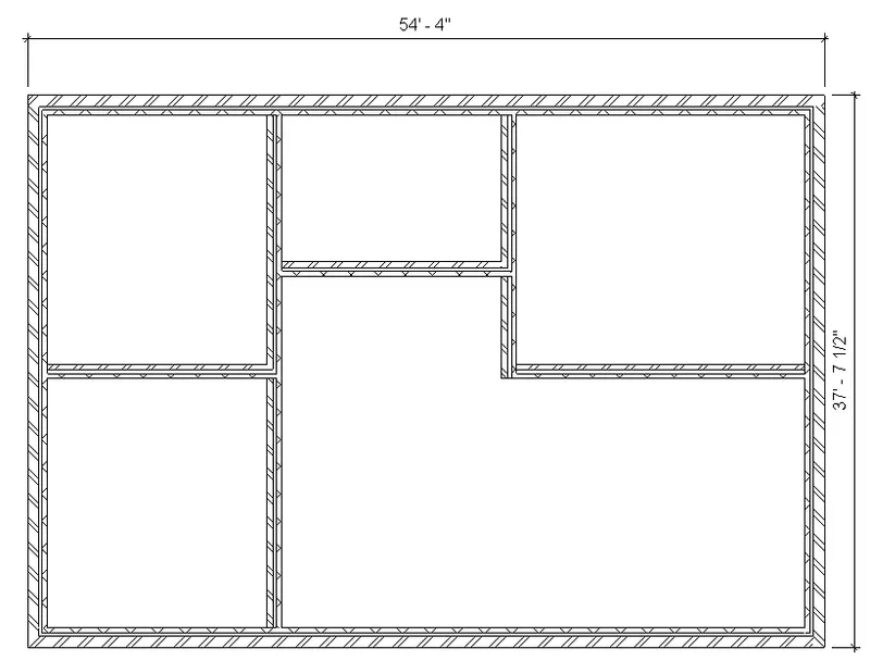
STEP 3:
Next change the residential layout plan to the 3d view as shown below
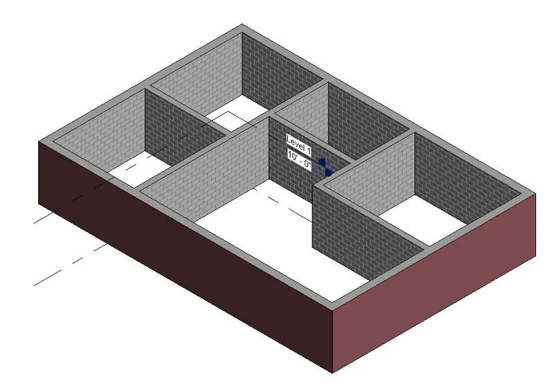
RESULT:
The conceptual layout of the residential unit is created sucessfully in the revit in detailed manner
6) AIM:
To draft the level of details you are planning including dimensions of room, components to add in the residential unit.
INTRODUCTION:
Dimensioning on a floor plan usually requires two or three continous dimensional lines to locate exterior walls, wall jogs, interior walls , windows , doors and other elements
Exterior walls of a building are dimensioned outside the floor plan .
The outermost dimensional line is the overall building dimension
The next dimension line, moving towards the plan , indicates wall locations and centerlines to doors and windows
Other miscellanious details in the plan are located on a third dimension line
PROCEDURE:
STEP 1
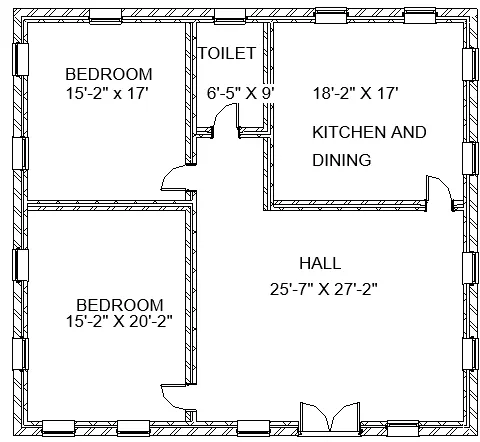
From the previous drawn residential unit, we put the dimensions for the rooms as shown below
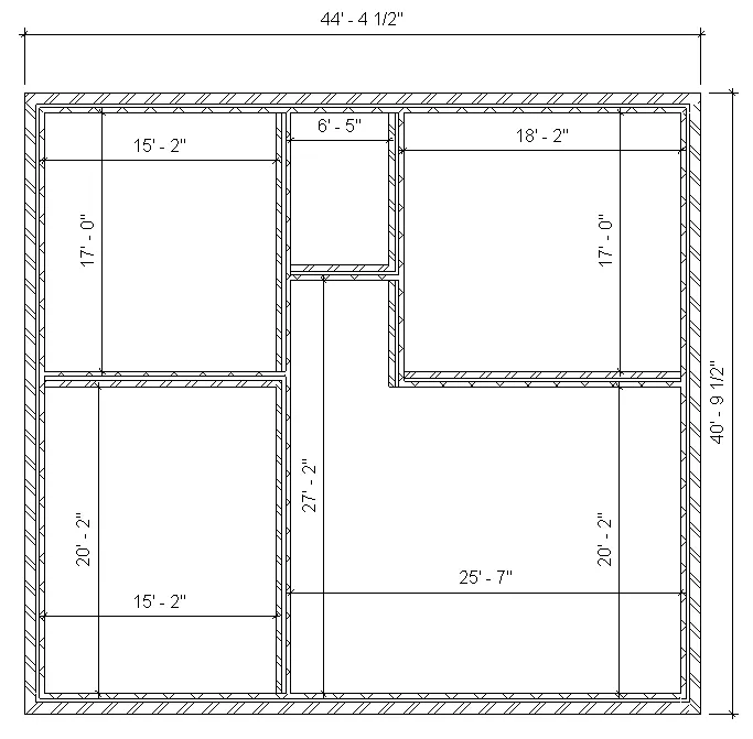
STEP 2:
Next we need to add the doors to the layout using the door option in the architecture toolbar
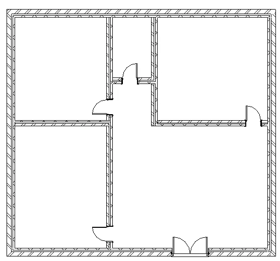
STEP 3:
Next we need to add the windows to the layout using the window option in the architecture toolbar
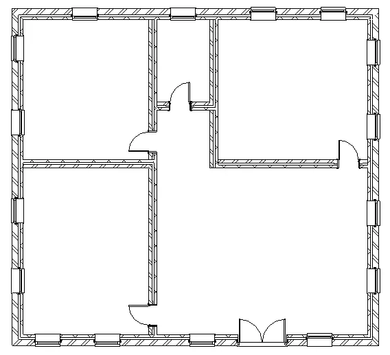
STEP 4:
Next we write the room names and dimensions using text tool, the text tool will be at the top of the screen as shown below
STEP 5:
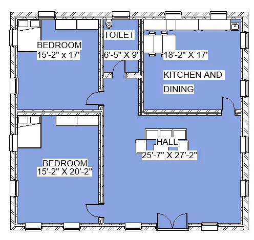
Next we use the floor option to provide the floor for the resdential unit as shown below
The floor option will be there in the architecture toolbar
STEP 6:
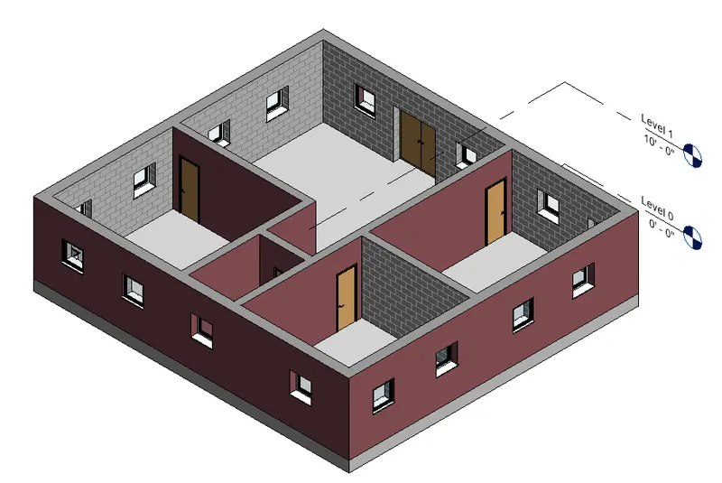
Next the residential unit is changed to the 3d view as shown below
RESULT:
The level of details whivh include dimensions of the room, components are sucessfully added in the residential unit
7. AIM:
To insert the residential model elements such as Door, Windows, Tables, Chair, Couch, Bed, Lamps from the library and insert them to the model
INTRODUCTION:
The residential model elements are Door, Windows, Tables, Chair, Couch, Bed, Lamps
These elements are very important in the building model for construction
Coming to the 3d modelling in the revit,these elements are present in the library and we need to insert them into the model
PROCEDURE :
STEP 1:
We need to add the doors to the layout using the door option in the architecture toolbar
STEP 2:
Next we need to add the windows to the layout using the window option in the architecture toolbar
STEP 3:
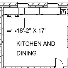
Next we need to insert the dining table, kitchen table, kitcen sink and counter as shown in the figure
STEP 4:
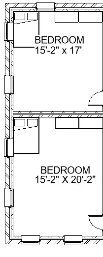
Coming to the bedroom we insert the beds, chairs, and tables from the library as shown below
STEP 5:
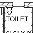
Next coming to the toilet room, we Insert the W/C from the library as shown in the screenshot
STEP 6:
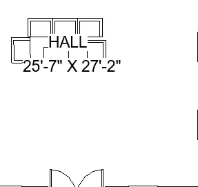
Next we insert the furniture things in the hall from the library as shown in the picture below
STEP 7:
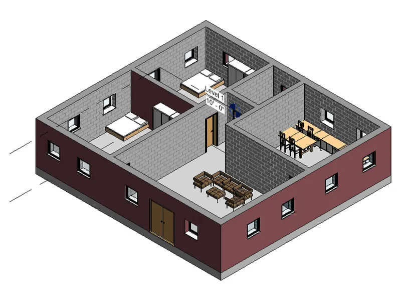
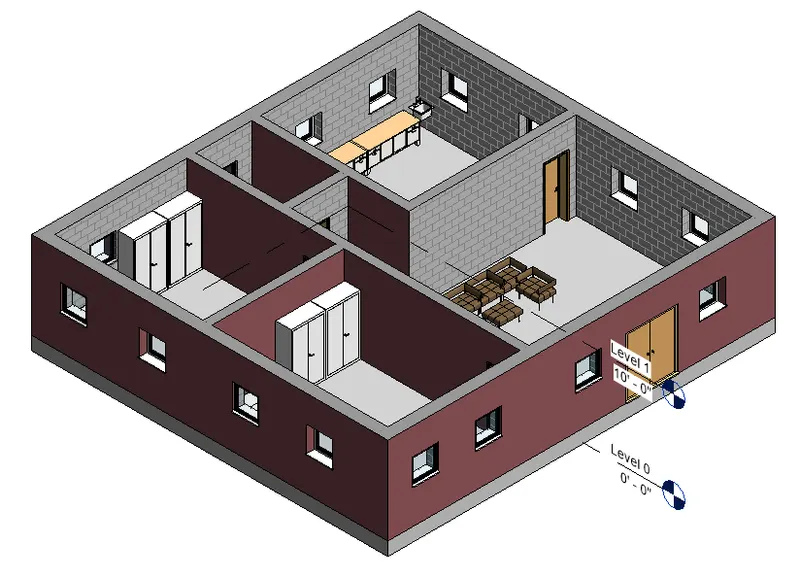
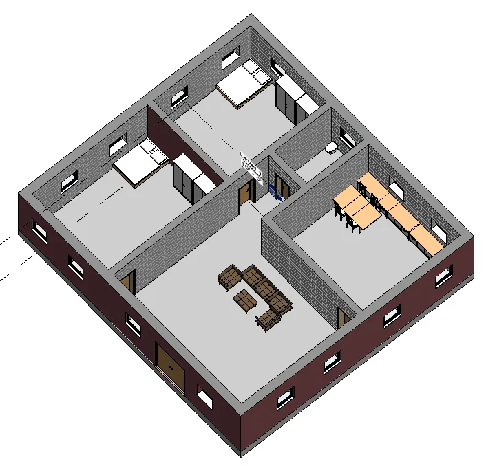
The residential model elements are inserted from the library as shown below in the picture
STEP 8:
The model elements are inserted in the model sucessfully and different views are shown
VIEW 2
VIEW 3
RESULT:
Residential model elements such as Door, Windows, Tables, Chair, Couch, Bed, Lamps are inserted in the model from the library in the model