Creating Levels, Grids, Layout and model elements for a residential unit using REVIT
ANS.1.
BIM :-
The full form of BIM is building information modelling. So building information modelling refers to the process of creating and managing the information for a built asset. It is a process for creating and managing information on a construction project throughout its whole life cycle.
A digital description of every aspect of the build asset is developed in this process by using a set of appropriate Technology. This digital description includes a combination of 3D models and associated structure data such as product and execution or hand over informations etc.
FEATURES OF BIM :-
The main goal of using BIM is to create a 3D model and hence a 3D model enables user to understand the relationship between space materials and various items within a physical structure. It can be used in every step of the process from planning to designing to construction.
a.Planning :-
Building information modelling user starts by drafting an initial design with the help of the software. And it also I losers to make it possible to use multiple users simultaneously work on a design at the same time. And hence after the initial design is complete user can present the design to for approval to move forward.
b.3d Modelling :-
Once a 3D model is created then then it is possible to visualize the various elements of the physical building if the help of the building information modelling. It provides us that how the building will look in the real life after it is constructed.
c.Construction :-
After the 3D modelling stages completed then the designed design is given to the whoever project manager is or to the contractor so that the project can start in real life and hens the construction process begins.
BENEFITS OF USING BIM OVER 2D CAD TOOL :-
Building information modelling helps to improve the onsite collaboration and communication.
By using BIM, we can plan and visualise the entire project during the preconstruction process only.
It also I lost us to better coordinate trade and sub contractors and help in deducting any MEP, internal or external classes before construction begins.
It also help us to mitigate that risk and to reduce the cost by lowering the wastage of resources during construction process.
It helps in improving the scheduling and Sequencing of the construction project. It health us to allow design and documentation to be done at the same time.
It helps increasing the productivity with prefabrication.
It can also improve the construction safety by pin pointing the hazards before they become problem and avoid physical risk by visualising and planning site logistics before time.
The increase the reliability of a coordinated model leads directly to Greater building quality and hence it execute overall build quality.
ANS.2.
AIM :-
To understand the concept of categories, family and elements in Revit software and also to insert them in the drawn model.
INTRODUCTION :-
Here we use Revit software to understand the concept of categories families and elements and also to insert them in the project model. We know that Revit software is a 3D modelling software which is used to draw 3D objects and is a very useful software for engineers of any field.
PROCEDURE :-
1. The first step involves is to open the Revit software and open the previous project which we made and edited as per requirement.
2. Then the next step involves is to go to the architectural tab and click on the door option to insert the doors.
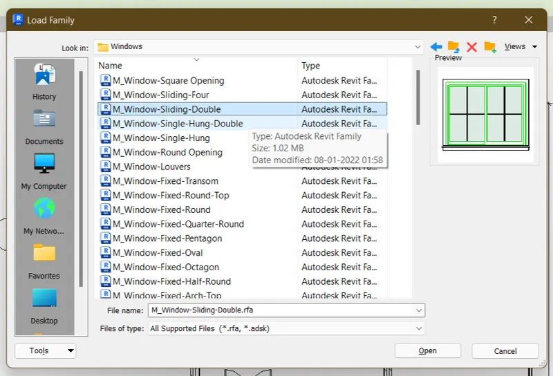
3. Then there opens the modify/ place door tab and then click on the load family option.

4. After that select on the US option to proceed the further procedure.
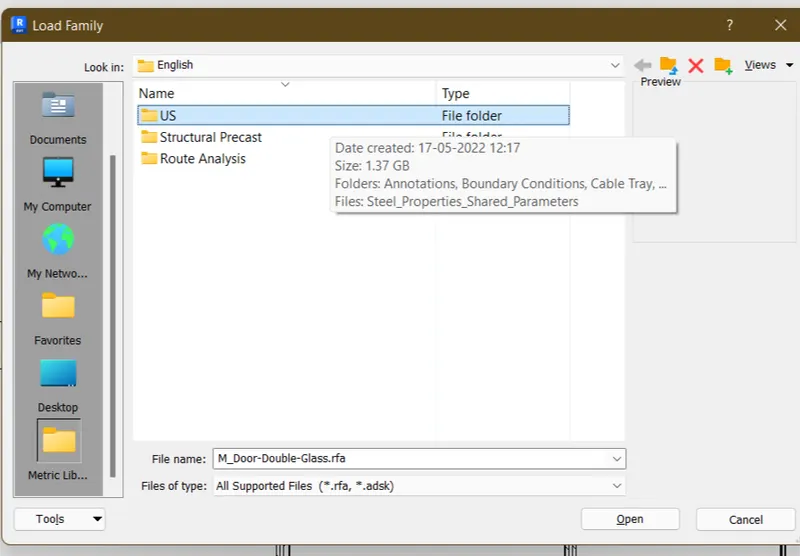
5. Then select the door and open it and select a door
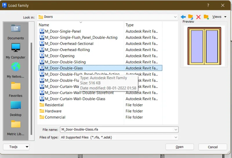
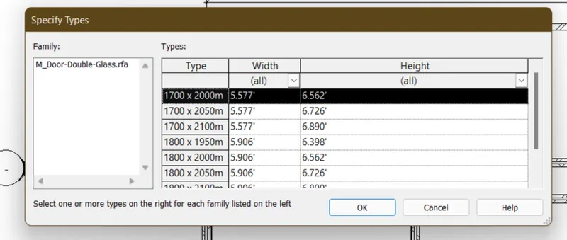
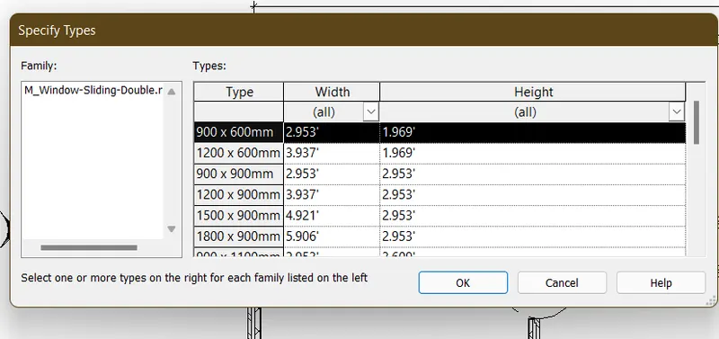
6. After the selection of door select with the proper size of the door and then click ok.
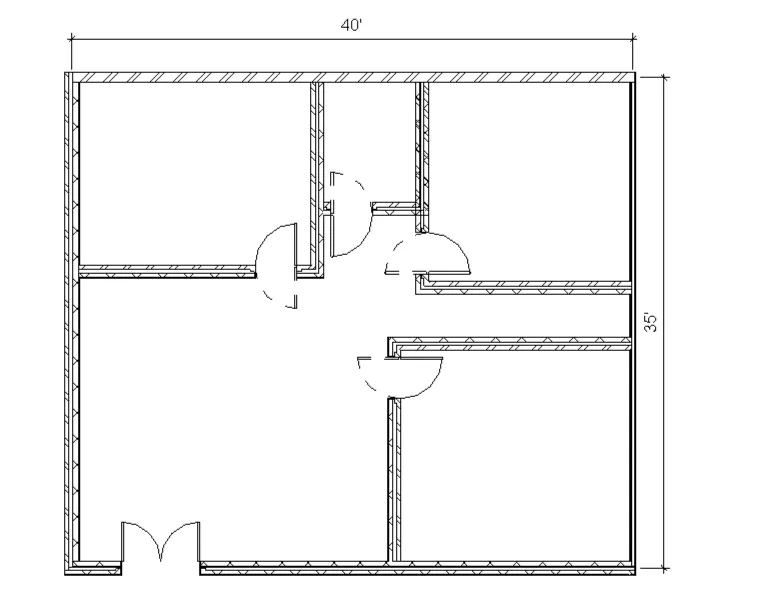
7. Place the door wherever is required in the model.
8. Similarly for inserting Windows in the drawing model follow the same steps as followed for inserting the doors.
RESULT :-
Hence concept of categories, families and elements is properly understood and also inserted in the drawing model.
ANS.3.
AIM :-
To open a project with architectural template then save the file with appropriate name and also complete the project information and to set up the maximum backups for project file to 3.
INTRODUCTION :-
Revit software is used as a 3D modelling software and is a very useful software for engineers and architectures to design 3D models. It can also be said that it is the upgraded version of autocad and is used widely in every construction modelling.
PROCEDURE :-
To open a project file with architectural template
As the project that we have created is in the architectural template only so to open that go to models then click on the open option
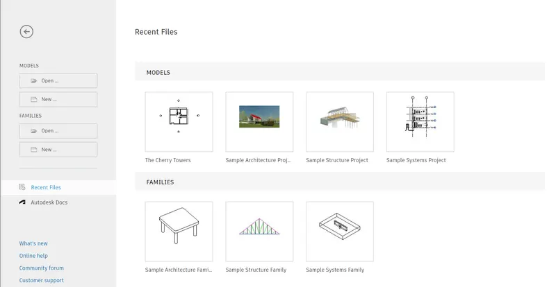
Then select the project file which we have created and hence the project file opens.
To save the file with appropriate name :-
To save the project go to the file option and go to the save as option and then go to the project option.
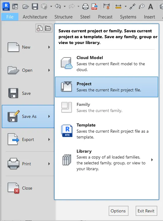
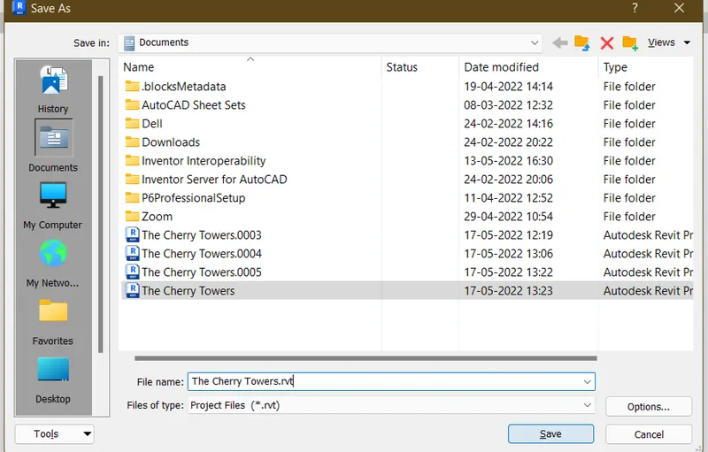
After that provide a proper name for the file and click on the save to save the file.
To complete the project information :-
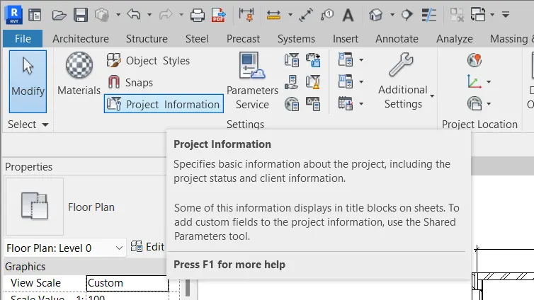
Go to the manage tab and then click on the project information option that is available there.
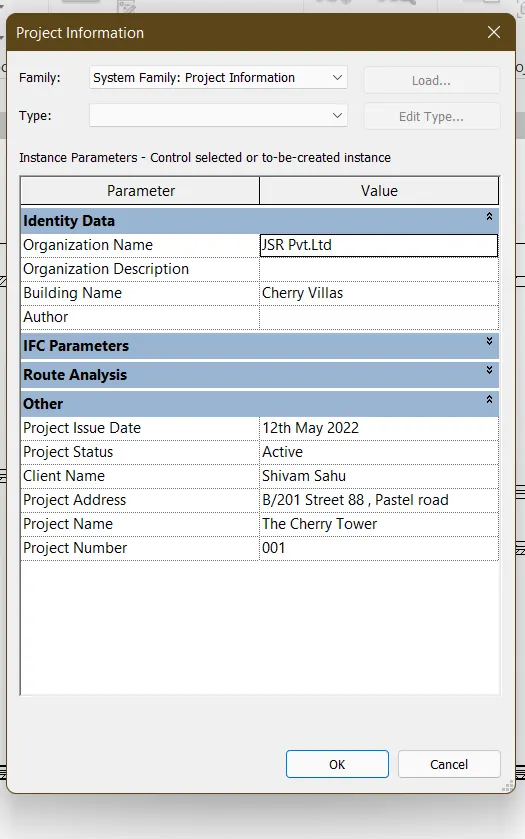
A dialogue box open then give the proper information of the project as per your need and then click on ok.
To make the project backup :-
Again go to the file tab and open then go to the save as option and then go to the project option.
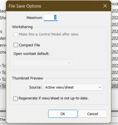
Then there opens a dialogue box and then go to the options that is available in the bottom and after clicking on it, enter the maximum number of backups you needed and then click on Ok
Hence backups are created.
RESULT :-
Hence the project has been saved and then opened and also the project information is completed and maximum number of backups are done as per given question
ANS.4.
AIM :-
To understand the concept of levels and greeds and also create levels as per the given dimensions in the layout.
INTRODUCTION :-
Revit software is used as a 3D modelling software and is a very useful software for engineers and architectures to design 3D models. It can also be said that it is the upgraded version of autocad and is used widely in every construction modelling.
PROCEDURE :-
1. For creating levels and grids , firstly we have to open the project or model in which we want to insert levels and grid. After opening of the project go to the elevation view because in any other views the level option is not available.
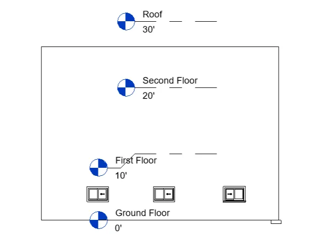
As you will see there were two levels that are created by default. So now let's create other levels as per the given dimensions.

You can change the name of the default levels that are given as per the requirement
To create a new level
Go to the architecture tab and then click on the level option
There will be two different types to create the levels. Select the pick point option and then enter the offset distance as 10 ft

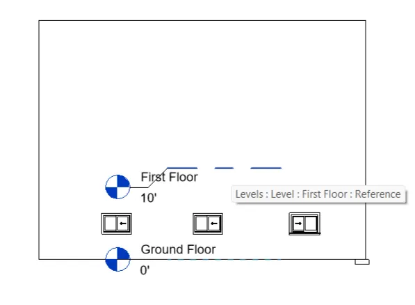
Then go to the default created levels and placing the mouse cursor to them a level is shown click their to create the next level and similarly do the same for another levels.
After that rename the created levels as per the requirement. And hence levels are created..
Now to draw the grids
Similarly go to the architectural tab where the grids are available below the level option click on them and here select the line option to draw the Grids.
Grid can be created in any view as there are no restrictions for drawing of grids.
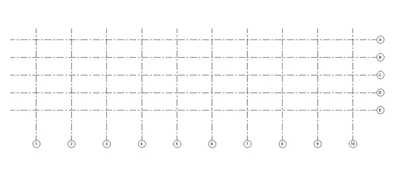
Then draw the grids by selecting the grid option and draw a line longitudinally.
After that again go to grid option and then select the pic point option from their to draw the grid and give the offset distance as 20ft and draw the other required number of grids.
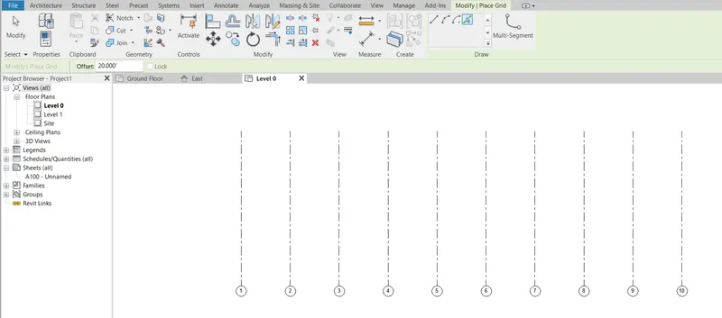
Then to create the grids in transverse go to the grid option again and then select the line option and draw a grade line transversely.
Then again go to the grid option and select the pic point option and give the offset distance as 10 feet and draw the other required grades and name them as a b c d e f.
RESULT :-
Hence the levels are being created and the grids are also drawn as per the given question.
ANS.5.
AIM :-
To create a 3D model of residential unit.
INTRODUCTION :-
Revit software is used as a 3D modelling software and is a very useful software for engineers and architectures to design 3D models. It can also be said that it is the upgraded version of autocad and is used widely in every construction modelling.
PROCEDURE :-
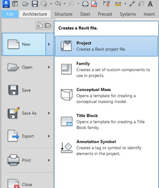
1. Open Revit software and then go to new option and then go to project
2. Give proper unit by pressing U to set the units.
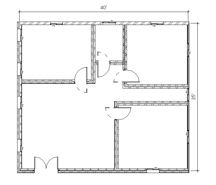
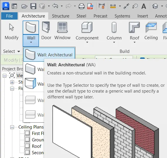
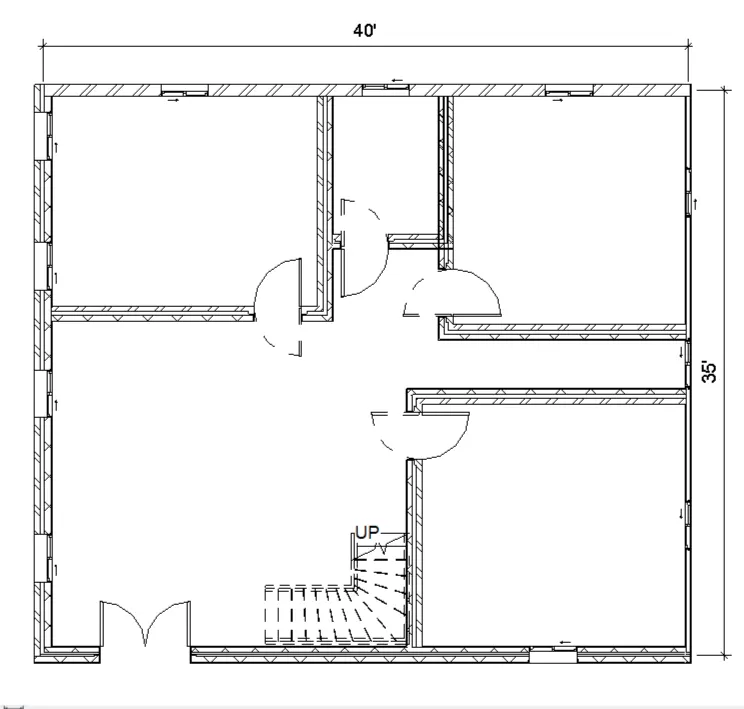
3. Then go to architectural tab and select the wall option and draw a Wall of dimension 40' x35' .
4.Then draw interior room as per requirement.
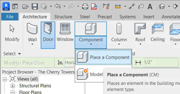
5.Then place door and windows in it at desired places by going to the architecture tab and selecting door and Windows option.
Then go to the load family option and attach the required door and Windows in the figure.

6. Once the plan is completed use the dimension tool to dimension the created plan
For that go to the annotate toolbar and there will occur the different types of dimensions select any of the dimension ( I selected linear dimension) and then dimension the created plan.
RESULT :-
Hence a plan is being created using the Revit software.
ANS.6.
AIM :-
To dimesion and include details in the created plan.
INTRODUCTION :-
Revit software is used as a 3D modelling software and is a very useful software for engineers and architectures to design 3D models. It can also be said that it is the upgraded version of autocad and is used widely in every construction modelling.
PROCEDURE :-
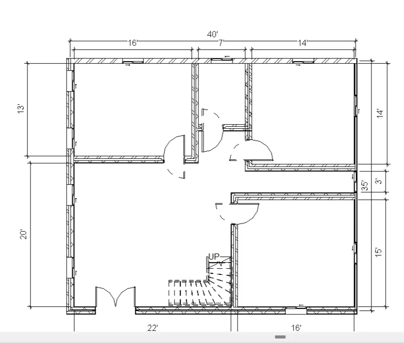
1. To dimension the created plan following steps are involved
Open the created plan
Go to the annotate toolbar and select the dimension type
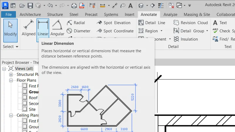
After selecting the dimension type go to the created plan and then dimension wherever needed
Hence the created plant is being dimensiond with the help of dimension toolbar.
2. To add different components in the plan :-
To add different components in the plan go to the architecture toolbar and their appears are option named component
Select the component and then go to the place a component option
A new tab opens and their go to the load family option and at which ever component you needed.
RESULT :-
Hence the created plan is being dimensioned and some different components are also added in it.
ANS.7.
AIM :-
To add model element such as door Windows tables chair couch bed lamp extra from the library to insert them in the model and then save the project.
INTRODUCTION :-
Revit software is used as a 3D modelling software and is a very useful software for engineers and architectures to design 3D models. It can also be said that it is the upgraded version of autocad and is used widely in every construction modelling.
PROCEDURE :-
Steps taken to insert the different model elements in the creator plan are as follows :-
Open the created plan
Then go to the architectural tab and their occurs a component toolbar
Click on the component tool bar and there appears of place a component option then click on it.
After clicking on it the tab changes and then go to the load family option which is available there in that tab only.
Then a dialogue box opens and hence select the components which are all required as per the given requirements
Once all the components are placed click ok to exit the tab
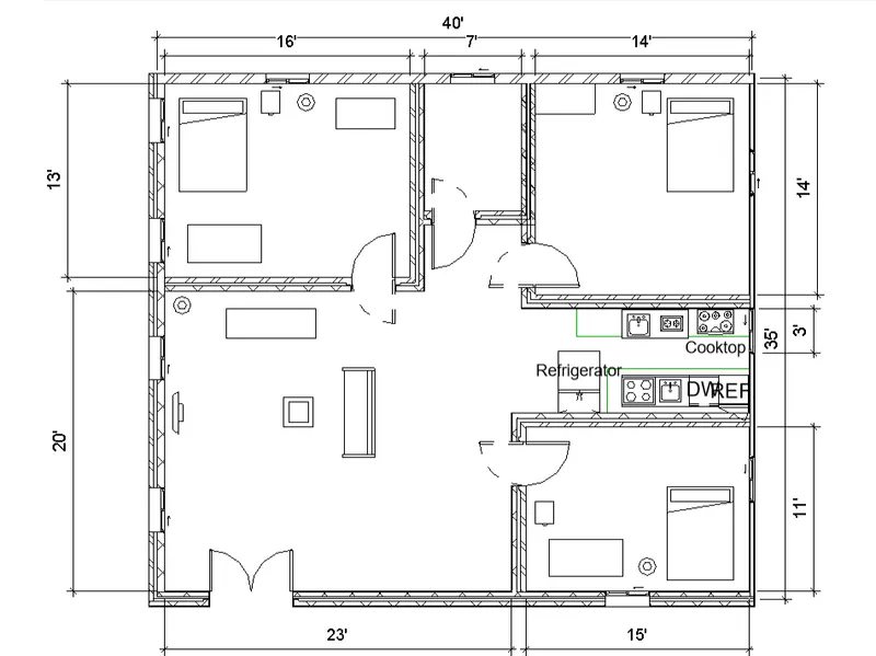
To save the file go to the save as option and then go to the project option and then provide a name of that project and then click on the save option to save the project.
RESULT :-
Hence model elements are added in the plant from the library and hance the project has been saved.