Drafting of various geometries using Chamfer, Fillet tool in AutoCad
Ans 1. Creating Geometry in DECIMAL unit
AIM :-
The aim here is to create a geometry in decimal unit using chamfer ,fillet tool in autocad.
INTRODUCTION :-
Autocad is a drafting software which was introduced in 1979 and since then it is used world widely and it is the most important software for engineers, It can be used for Drafting , Visualizations , drawing a map , creating geometries etc.It is a very useful and handy software.
PROCEDURE :-
1. The first step involved for the creation of a geometry in decimal unit is to open AutoCAD and then select the decimal unit from the setup. You can use quick setup or advance setup as per your convenience.
2. After selecting the decimal unit we have to mention the area also and after mentioning that a drawing page opens in AutoCad software.
3. Then select the line tool or or a polyline tool for the creation of geometry as it is a closed figure it can also be created by using polyline tool also from toolbar.
4. Here I used polyline tool. After selecting file and tool give the the coordinates as (1,1) and then start drawing the figure.
5.Enter the dimensions, angles which are given in the figure and draw the diagram.
6. After completing the required figure, close the program by clicking on enter and then select the circle tool to draw the circle in between the figure as per the given figure.
7. Enter the diameter or radius of the circle Which ever is given in the figure and draw that circle.
8. After that use the dimension tool which is available on the toolbar to dimension the figure. Type DIMANG to give the dimension of angles and type DIMRAD or DIMDIA to dimension the radius or diameter of the circle.
9. After that save the file by pressing the Control +S or directly from autocad icon .
10.After that for attaching it in the answer ,we can use the print option and there we can select the printer or plotter option with the name to be in the JPG format and then click on preview option for seeing that and then print it out it will be saved in the system
RESULT :-
The created geometry is attached below :

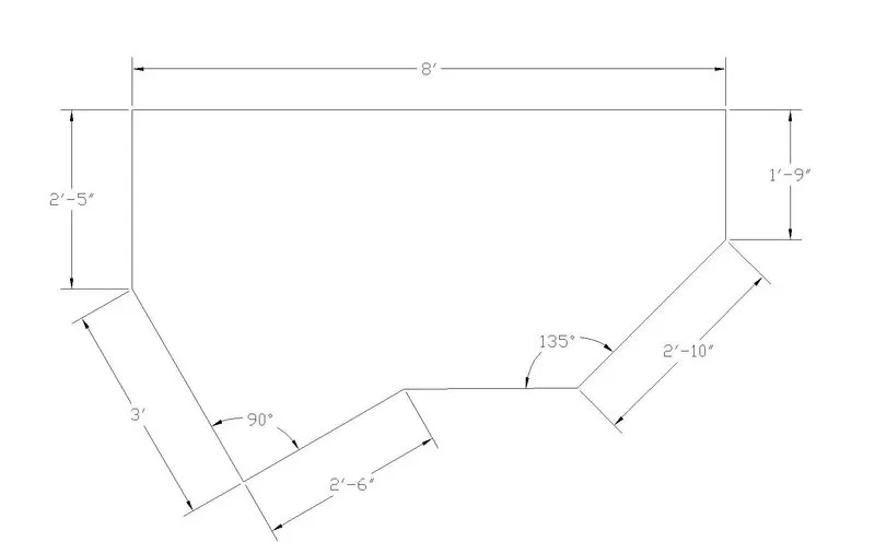
Ans2.
AIM :-
Here the aim is to create the given geometric figure in Architectural mode using chamfer and fillet tool in autocad.
INTRODUCTION :-
Autocad is a drafting software which was introduced in 1979 and since then it is used world widely and it is the most important software for engineers, It can be used for Drafting , Visualizations , drawing a map , creating geometries etc.It is a very useful and handy software.
PROCEDURE :-
1.Open AutoCAD and then select the new option and use setup with architectural mode.
2.Now after that select polyline tool and enter any coordinate for ex.(1,1) , then after that enter the given value as dimension and then start drawing.
3.It should be kept in mind that the mode we are using here is architectural mode so for that the mentioned values must be in feet and inches.So values should be entered in feet and inches as dimensions.
4. For creating the figure in y axis put the cursor up or down as per the given figure enter the value given and draw the figure.
5. Calculate the required angle and then draw the figure as per the calculated angle and also use the given dimensions to draw the figure and complete it.
6. After the completion of the figure the dimension tool is used to give the dimensioning of the figure
7.After that for attaching it in the answer ,we can use the print option and there we can select the printer or plotter option with the name to be in the JPG format and then click on preview option for seeing that and then print it out it will be saved in the system.
8. If you want to save the project simply Press control + s and will be saved or you can save it from the AutoCAD icon option also.
RESULT :-
Created figure is attached below :-
Ans3.
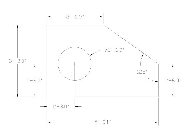
AIM :-
Aim is to create the given geometric figure in Engineering mode using Chamfer ,fillet tools
INTRODUCTION :-
Autocad is a drafting software which was introduced in 1979 and since then it is used world widely and it is the most important software for engineers, It can be used for Drafting , Visualizations , drawing a map , creating geometries etc.It is a very useful and handy software.
PROCEDURE :-
1. Open AutoCAD and then select the new option and use setup with Engineering mode.
2. After that select line tool and then start creating the given figure.Firstly i create a reactangle by using the given dimension. Use any co-ordinate system as per your convenience as no coordinate system is mentioned.
3.Now after creating a rectangle , we select the chamfer tool from the tool bar and then select the distance option given.
4. Before selecting Champher tool , I have given the dimensions which are given as per figure by using the dimension tool. And then we used chamfer tool.
5. Specifying the distance that we have calculated by using the dimension tool. Hit needs the first chamfer distance which should be entered and then we have to give the second chamfer distance and then enter.
6. After that it will say to select the first line and after selecting the first line it will automatically tell to select the second line and after selecting it the chamfering is done.
7.Then complete the figure , select the circle tool and create a circle with the given points as diameter and the length that are given from the specific starting point and intersect them to get the intersection point and from there create a circle of given diameter.
8. Then complete the dimensions has all the angles and length should be mentioned by using the dim angular and dimension tool. Hence the figure is completed.
9.After that for attaching it in the answer ,we can use the print option and there we can select the printer or plotter option with the name to be in the JPG format and then click on preview option for seeing that and then print it out it will be saved in the system.
10. If you want to save the project simply Press control + s and will be saved or you can save it from the AutoCAD icon option also.
RESULT :-
The created geometry in architectural mode in attached below.
Ans4.
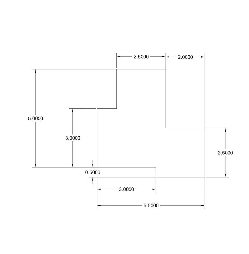
AIM :-
To create the given geometry using autocad software
INTRODUCTION :-
Autocad is a drafting software which was introduced in 1979 and since then it is used world widely and it is the most important software for engineers, It can be used for Drafting , Visualizations , drawing a map , creating geometries etc.It is a very useful and handy software
PROCEDURE :-
1.First step involves open autocad and then select a unit of your convenience.
2. Select line tool from the toolbar and then specify coordinates as per your need. You can also use free co-ordinate system.
3. After that enter the given dimension value and start creating the figure. To create the figure in y axis you can move the cursor up or down as per the requirement of the figure.
4. After moving the cursor up or down as the requirement of figure you can enter the value that is required to complete the figure.
5. After the figure has been created using the line tool and dimensions given then you can trim the figure to make it more accurate.
6. The trim option can be selected from the tool bar or you can selected by giving command of trim in the command bar.
7. After trimming of the figure has been done, the dimension tool came into use to dimension the created geometry.
8. Dimension tool can be used from the toolbar or by giving a command of dim from the command bar.
9.After that for attaching it in the answer ,we can use the print option and there we can select the printer or plotter option with the name to be in the JPG format and then click on preview option for seeing that and then print it out it will be saved in the system.
10.If you want to save the project simply Press control + s and will be saved or you can save it from the AutoCAD icon option also.
RESULT :-
The created geometry is attached below
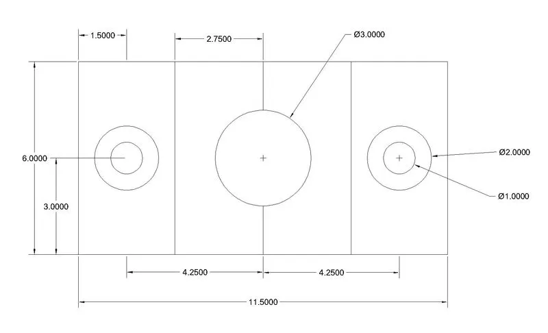
ANS 5
AIM :-
To create the given geometry using autocad software
INTRODUCTION :-
Autocad is a drafting software which was introduced in 1979 and since then it is used world widely and it is the most important software for engineers, It can be used for Drafting , Visualizations , drawing a map , creating geometries etc.It is a very useful and handy software
PROCEDURE :-
1.First step involves open autocad and then select a unit of your convenience.
2. Select line tool from the toolbar and then specify coordinates as per your need. You can also use free co-ordinate system.
3. After that enter the given dimension value and start creating the figure. To create the figure in y axis you can move the cursor up or down as per the requirement of the figure.
4. After moving the cursor up or down as the requirement of figure you can enter the value that is required to complete the figure.
5. After the figure has been created using the line tool and dimensions given then you can trim the figure to make it more accurate.
6. The trim option can be selected from the tool bar or you can selected by giving command of trim in the command bar.
7. To create circle select the circle tool from the toolbar and gives a required radius or diameter which level is given in the question to create a circle.
8.After the figure has been completed the dimensioning of the figure can be done using the dimension tool. Dimension tool can be used from the toolbar or by giving a command of dim from the command bar.
9.After that for attaching it in the answer ,we can use the print option and there we can select the printer or plotter option with the name to be in the JPG format and then click on preview option for seeing that and then print it out it will be saved in the system.
10.If you want to save the project simply Press control + s and will be saved or you can save it from the AutoCAD icon option also.
RESULT :-
The created geometry is attached below
ANS 6.
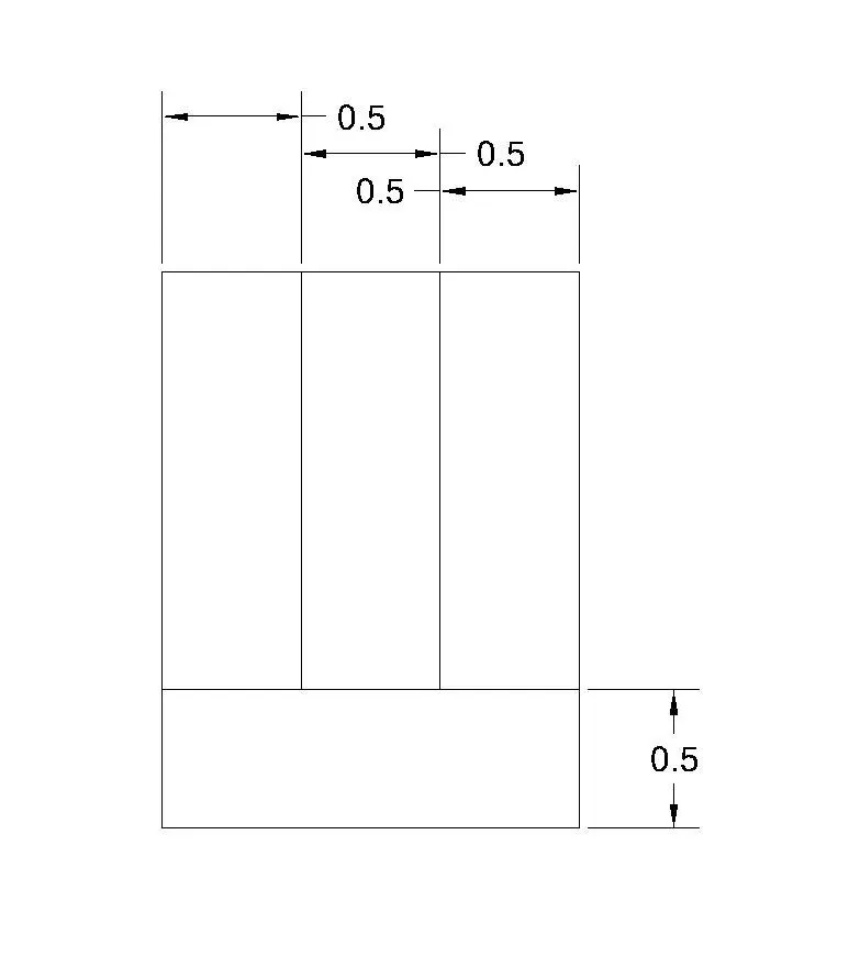
6(a) AIM
To create the given geometry using autocad software
INTRODUCTION :-
Autocad is a drafting software which was introduced in 1979 and since then it is used world widely and it is the most important software for engineers, It can be used for Drafting , Visualizations , drawing a map , creating geometries etc.It is a very useful and handy software
PROCEDURE :-
1.Here the First step involves is to open autocad and then select a unit of your convenience.
2. Select line tool from the toolbar and then specify coordinates as per your need. You can also use free co-ordinate system.
3. After that enter the given dimension value and start creating the figure. To create the figure in y axis you can move the cursor up or down as per the requirement of the figure.
4. After moving the cursor up or down as the requirement of figure you can enter the value that is required to complete the figure.
5. After the figure has been created using the line tool and dimensions can be mentioned as given for the figure
6. Dimension tool can be used from the toolbar or by giving a command of dim from the command bar.
7.After that for attaching it in the answer ,we can use the print option and there we can select the printer or plotter option with the name to be in the JPG format and then click on preview option for seeing that and then print it out it will be saved in the system.
8.If you want to save the project simply Press control + s and will be saved or you can save it from the AutoCAD icon option also.
RESULT :-
The created geometry is attached below .
6(b)
AIM
To create the given geometry using autocad software
INTRODUCTION :-
Autocad is a drafting software which was introduced in 1979 and since then it is used world widely and it is the most important software for engineers, It can be used for Drafting , Visualizations , drawing a map , creating geometries etc.It is a very useful and handy software
PROCEDURE :-
1.Here the First step involves is to open autocad and then select a unit of your convenience.
2. Select line tool from the toolbar and then specify coordinates as per your need. You can also use free co-ordinate system.
3. After that enter the given dimension value and start creating the figure. To create the figure in y axis you can move the cursor up or down as per the requirement of the figure
4. After moving the cursor up or down as the requirement of figure you can enter the value that is required to complete the figure.
5. After the figure has been created using the line tool and dimensions can be mentioned as given for the figure
6. Dimension tool can be used from the toolbar or by giving a command of dim from the command bar.
7.After that for attaching it in the answer ,we can use the print option and there we can select the printer or plotter option with the name to be in the JPG format and then click on preview option for seeing that and then print it out it will be saved in the system.
8.If you want to save the project simply Press control + s and will be saved or you can save it from the AutoCAD icon option also.
RESULT :-
The created geometry is attached below .
6(c)
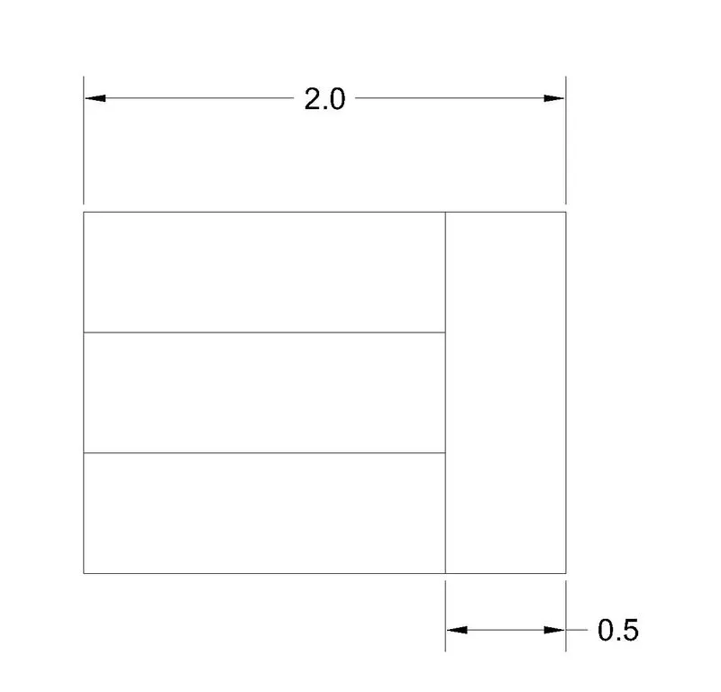
AIM
To create the given geometry using autocad software
INTRODUCTION :-
Autocad is a drafting software which was introduced in 1979 and since then it is used world widely and it is the most important software for engineers, It can be used for Drafting , Visualizations , drawing a map , creating geometries etc.It is a very useful and handy software
PROCEDURE :-
1.Here the First step involves is to open autocad and then select a unit of your convenience.
2. Select line tool from the toolbar and then specify coordinates as per your need. You can also use free co-ordinate system.
3. After that enter the given dimension value and start creating the figure. To create the figure in y axis you can move the cursor up or down as per the requirement of the figure.
4. After moving the cursor up or down as the requirement of figure you can enter the value that is required to complete the figure.
5. After the figure has been created using the line tool and dimensions can be mentioned as given for the figure
6. Dimension tool can be used from the toolbar or by giving a command of dim from the command bar.
7.After that for attaching it in the answer ,we can use the print option and there we can select the printer or plotter option with the name to be in the JPG format and then click on preview option for seeing that and then print it out it will be saved in the system.
8.If you want to save the project simply Press control + s and will be saved or you can save it from the AutoCAD icon option also.
RESULT :-
The created geometry is attached below .
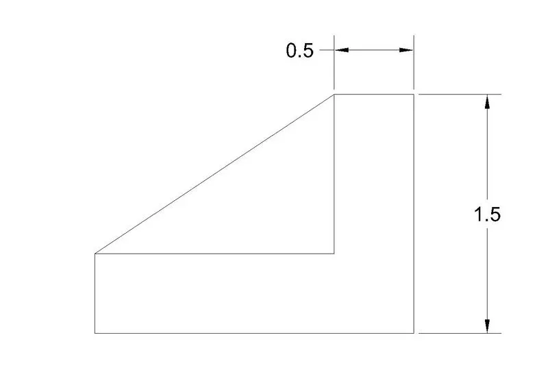
ANS 7.
AIM :-
Here aim is to create the given figure in AutoCad
INTRODUCTION :-
Autocad is a drafting software which was introduced in 1979 and since then it is used world widely and it is the most important software for engineers, It can be used for Drafting , Visualizations , drawing a map , creating geometries etc.It is a very useful and handy software
PROCEDURE :-
1.Open autocad and select the setup.
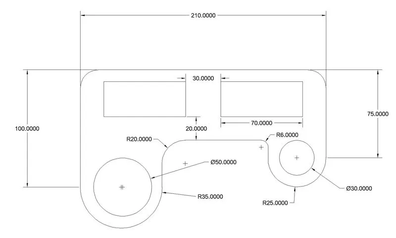
2.After that draw a line of 210 units from a random point with the help of a line tool in x axis.
3. After that draw a line of 75 units in Y direction by moving the cursor down.
4. Use the fillet tool now in both the As given in the figure. Select the first line and then select the radius option and enter radius of 15 unit and then select second line and hence fillet is done.
5. Now move to the starting point of the line to 210 units and from the the starting point of that line draw line of 100 units in Y direction.
6. After that from the line in x axis 210 units , draw a line which should be 10 units down in Y axis.Then create a rectangle of length 70 units and width 30 units from both the sides.
7. Indirect angle is created draw a line from the base of the rectangle which should be 20 units down from there and then create up perpendicular line to that line.
8. No select the circle option and then create a circle from the edge of the rectangle which is in the right side and the circle should be of diameter 30 units. After that use the fillet tool and provide radius of 25 units by selecting the radius option in the fillet and then selecting the second point makes the curve of radius 25 minutes
9. After that repeat the same procedure for the left hand side circle with diameter 50 units and curve with radius 35 unit. Fillet tool is used to get the desired curve there.
10. Now use the trim tool to trim the non required edges or sections so that the given figure is obtained or drawn.
11.Now use the dimension tool to dimension the figure and Hence you can also modify the size of dimensions as per your convenience or as per the need
After that for attaching it in the answer ,we can use the print option and there we can select the printer or plotter option with the name to be in the JPG format and then click on preview option for seeing that and then print it out it will be saved in the system.
RESULT :-
Created drawin is attached below
ANS 8.
AIM:-
To crreate the given figure using autocad software
INTRODUCTION :-
Autocad is a drafting software which was introduced in 1979 and since then it is used world widely and it is the most important software for engineers, It can be used for Drafting , Visualizations , drawing a map , creating geometries etc.It is a very useful and handy software
PROCEDURE :-
1. First step involves the use to open Autocad software and select a setup.(i selected decimal unit system for this figure).
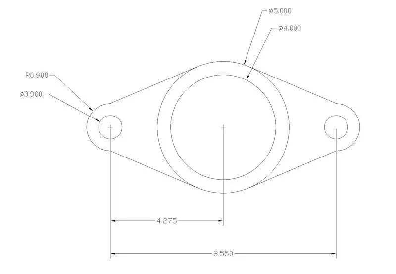
2. Then after opening Autocad software click on the the circle option from the toolbar and draw a circle of diameter 5 units in any random co-ordinate.
3. After drawing the first circle, turn on the centre from the snap cursor mode . Now with the same centre draw again a circle of diameter 4 units.
4. Now select line tool and draw a line of 4.275 units from the centre of the circle left and right from the centre.
5. After drawing the line, turn on the endpoint from the snapcursor mode, and after that use the end point of the line to draw a circle of diameter 0.9 units.
6. Apply the same procedure for the other side also.
7. Again draw a circle of radius 0.9 units from the same centre and do the same for the other side also.
8. Now turn on the tangent mode from the snapping cursor and select the circle with radius 0.9 and connect it with the help of tangent to the circle of diameter 0.5.
9. Apply the same procedure for other side too and connect the tangent to the circles
10. After that use the trim tool to make it accurate as per the given figure.
11.After that for attaching it in the answer ,we can use the print option and there we can select the printer or plotter option with the name to be in the JPG format and then click on preview option for seeing that and then print it out it will be saved in the system.
RESULT :-
Created figure is attached below :-
ANS 9.
AIM:-
To create the given figure using autocad software
INTRODUCTION :-
Autocad is a drafting software which was introduced in 1979 and since then it is used world widely and it is the most important software for engineers, It can be used for Drafting , Visualizations , drawing a map , creating geometries etc.It is a very useful and handy software
PROCEDURE :-
1. First step involves the use to open Autocad software and select a setup.Here architectural or engineering unit can be used.
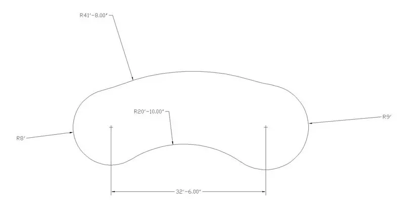
2.After that , draw a line using line tool of length 32'6.0".
3. After drawing the line draw two circles both at the end point of the line. To select the end point you must have on the end point option from the snapping cursor mode.
4. The first circle which is on the left hand side having radius of 8' and the second circle which is on the right hand side have is having a radius of 9'.
5. After drawing the circle, select the fillet option from the tool bar and and then select the radius option from the command bar and enter the radius as 41'8.0" and then select the first object in second object.
6. Same for the other side select field option and the radius option and enter the radius as 20'10.0" and then select the objects.
7. If you are not getting the desired shape of the figure then you can hold control button to switch is direction in the required direction.
8. Use the dimension tool to dimension the drawen figure.
9. Use the trim tool wherever it is required to trim the drawn figure as per the given figure.
10.After that for attaching it in the answer ,we can use the print option and there we can select the printer or plotter option with the name to be in the JPG format and then click on preview option for seeing that and then print it out it will be saved in the system.
RESULT :-
Drawn figure is attached below :-
ANS 10
AIM:-
To create the given figure using autocad software
INTRODUCTION :-
Autocad is a drafting software which was introduced in 1979 and since then it is used world widely and it is the most important software for engineers, It can be used for Drafting , Visualizations , drawing a map , creating geometries etc.It is a very useful and handy software
PROCEDURE :-
1. First step involves the use to open Autocad software and select a setup.
2. Then select the rectangle tool and draw to rectangles of same dimension or you can use the copy tool after making the first rectangle.
3. Again draw two rectangles which must be smaller than the created first two bigger rectangles.
4. After that move the smaller rectangles inside the bigger rectangles for both the rectangle.
5. After moving the rectangles inside the bigger rectangles select one rectangle and select the rotate tool and specify the base point from which it should be rotated and rotate it in 45 degree angle.
6. After rotating the rectangle select the rectangle and again select the move option and move the rectangle above the Other rectangle.
7. After that use the trim tool to trim the drawn figure as per the given figure.
8.To make the edges with , First select the figure then Go to the quick properties and enter a value in the width option and enter ok .Entered width will be applied.
9.After that for attaching it in the answer ,we can use the print option and there we can select the printer or plotter option with the name to be in the JPG format and then click on preview option for seeing that and then print it out it will be saved in the system.
RESULT :-
Drawn figure is attached below :-

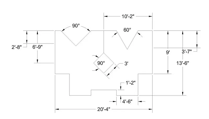
ANS11.
AIM:-
To create the given figure using autocad software
INTRODUCTION :-
Autocad is a drafting software which was introduced in 1979 and since then it is used world widely and it is the most important software for engineers, It can be used for Drafting , Visualizations , drawing a map , creating geometries etc.It is a very useful and handy software
PROCEDURE :-
1. First step involves the use to open Autocad software and select a setup.
2. After that select line tool from the tool bar and draw a line of 20'4" in x axis with Ortho Mode on.
3. After drawing the line in x axis move the cursor up to draw line in y axis of dimension 13'6".
4.Again draw a line of 20'4" in x axis moving the cursor in X axis and then move the Cursor in Y directions and draw the line of 13'6" in y axis.
5. Draw the line as per the required figure in x and y axis.
6. Now to draw the angle firstly trim the line which you have drawn first and then use the dimensions that are given , and draw the angle as per the calculations.
7. After completing the figure select the rectangle tool and draw rectangle of length 3' and width 3' and use the rotate tool to rotate it in 45 degree angle as for the required figure. And then place it as per the given dimensions.
8. After that use the trim tool to complete the figure or make it accurate and perfect and use the dimension tool to dimension the drawn figure.
9..After that for attaching it in the answer ,we can use the print option and there we can select the printer or plotter option with the name to be in the JPG format and then click on preview option for seeing that and then print it out it will be saved in the system.
RESULT :-
Drawn figure is attached below :-