Creating a Floor plan, Footing detail and Isometric view using AutoCad
Answer.
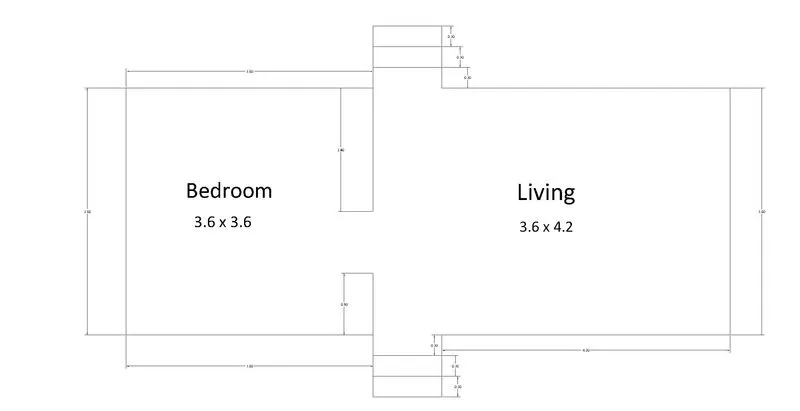
1.Creating a floor plan :-
(i). AIM :-
The aim here is to create a floor plan with the help of autocad software
(ii). INTRODUCTION :-
Autocad is a software which was firstly introduced in 1979 and was called as 'INTERACT CAD' .It was also referred as MICROCAD in early autodesk documents. Autocad is mainly used for drafting , drawing maps , visualizations , many other purposes.Its can be said that it is an important software for every engineer.
(iii). PROCEDURE :-
a. For creating a floor plan in AutoCad, the first step involves is to open Autocad software and then select a Setup .I selected Quick setup with Decimal unit of measurement and also given the area of page.
b. After that AutoCAD opens then select the line tool with Ortho Mode on and take a random co-ordinate as I have used a random co-ordinate and start drawing a line with the help of line tool as per the given dimensions.
c.As I have used free hand coordinate system , after drawing the line in the x axis of given dimensions, move the cursor up to draw the drawing in y axis as per the given dimensions.
d. After completion of the drawing with the given dimensions, for proper perfection of the drawing you can use the trim tool to make it accurate.
e. After all this you can use the dimension tool which can be invoke by typing a command DIM in the command bar.
f.You can also adjust the size of the dimensioning arrows and the text size of the dimensions by typing a command dimstyle in the command bar where you can modify the dimension size shape as per your need.
g.For adding text in drawn diagram , click on the TEXT option which is available on the tool bar and from there you can customize and add a text you want in your diagram.
h. For saving the file ,you can save it by clicking on the AutoCAD icon and there come the save option or you can use control button Ctrl+ S to save a file.
(iv). RESULT :-
Hence the drawn diagram of Floor plan using autocad software is given below ;
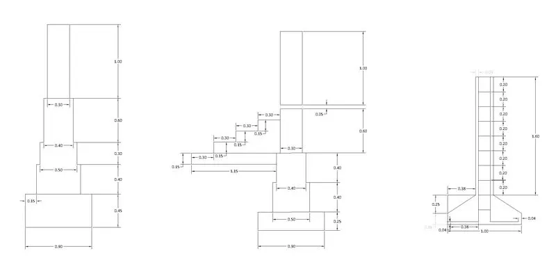
2.Creating Footing Detail :-
AIM :-
To create footing details with the help of Autocad software.
INTRODUCTION :-
Autocad is a software which was firstly introduced in 1979 and was called as 'INTERACT CAD' .It was also referred as MICROCAD in early autodesk documents. Autocad is mainly used for drafting , drawing maps , visualizations , many other purposes.Its can be said that it is an important software for every engineer.
PROCEDURE :-
1.First step involved for the creation of Footing details is open autocad software,do the setup , Quick or Advanced as per your need .
2.After that select coordinate systen as per mentioned in question , here i m using free hand co-ordinate system, and select the line tool to start the drawing.
3. You must have the Ortho mode on for the convenience of drawing line in x and y axis.
4. After selection of line tool, If you are using co-ordinate system then give the given coordinates that are mentioned in the drawing or if you are using free hand coordinate system then you can start it from any co-ordinate.
5. After starting with the coordinates give the dimension that are given in the figure and then start drawing. After the completion of the dimension in x-axis you can move the cursor up side to change the direction in y axis for the drawing of the given dimension in y axis.
6. Complete the drawing as per the given dimensions using the line tool and as per the need use the trim tool to make the the details more clear.
7. Trim tool can be invoke from the toolbar or you can type trim in the command bar to invoke the trim tool.
8. After trimming is done then you can mention the the dimensions of the figure which can be done by clicking on the dimension tool that is available in toolbar or you can type DIM in the command bar to invoke the dimension tool.
9. You can also customise the size of the dimensions that you are mentioning in the figure or diagram by typing dimstyle in the command bar where you can modify the dimension size and shape as per your need.
10. After the completion of the drawing you can save it it by pressing Ctrl + S ,or you can save it from the AutoCAD icon that is available on the left top by clicking the save option from there.
RESULT :-
The created footing details using the Autocad software is attached below :-
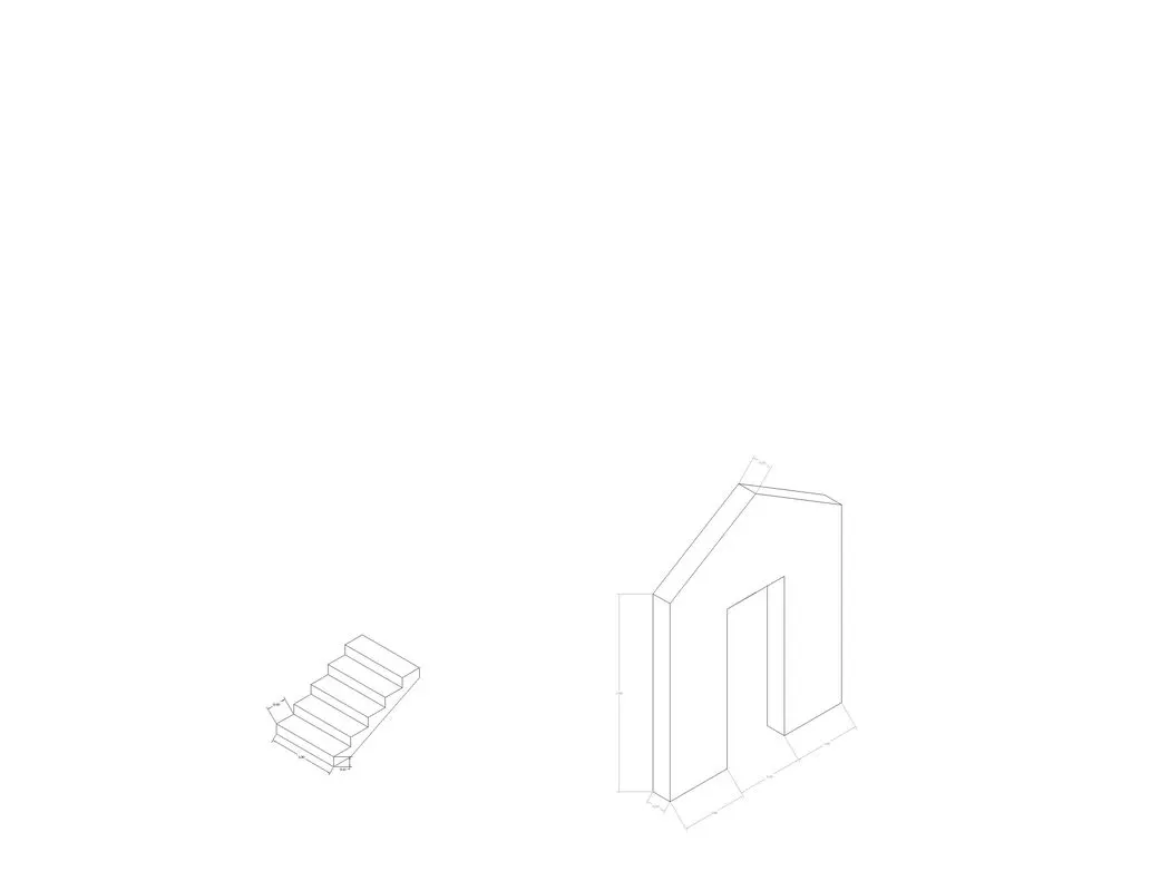
3.Creating a isometric view using Autocad
AIM :-
To create isometric view using autocad software.
INTRODUCTION :-
Autocad is a software which was firstly introduced in 1979 and was called as 'INTERACT CAD' .It was also referred as MICROCAD in early autodesk documents. Autocad is mainly used for drafting , drawing maps , visualizations , many other purposes.Its can be said that it is an important software for every engineer.
PROCEDURE :-
1.Frist step is to open autocad software and then select a setup as per your need .Here i used quick setup with decimal units .
2.Then for creating isometric view , we have to open drafting settings by giving a command of DS in the command bar and there open dialoge box from where we have to click on the snap on button and then below that there is snap type which contains of radio buttons in which we have to click on the isometric snap.
3. If you want to on the isometric view directly then click on the isometric drafting option and turn it on .
4. After this you have to select the line tool to create an object with the given dimensions and hence Ortho mode must be on during isometric drafting.
5. Then start drawing the object which you want to draw and there is a option in the isometric drafting setting which tells that isoplane left , isoplane right , isoplane top. They are used to allocate line in that direction according to the command selected.
6.That is if isoplane left is selected then the left facing planes or figure can be made or designed.For Isoplane top, it specifies creating top facing planes or design. Isoplane Right specify is creating right facing planes or design.
7. Hence, with the help of this command we can easily make lines or our figure in the required plane as per our need.
8. After the completion of the figure we can use the dimension tool to dimension the the created diagram which can be invoked by giving command of Dim from the command bar aur by clicking on the dimension tool from the toolbar.
9. When the figure is completed we have to save the file by using Ctrl + S command or directly from the AutoCAD icon by pressing of which we can get the save option.
RESULT :-
The created isometric view of staircase and gable wall are attached below :-