Creating a Residence Layout, Seating plan, Toilet and Utility room plan using AutoCad
Ans 1.
AIM :-
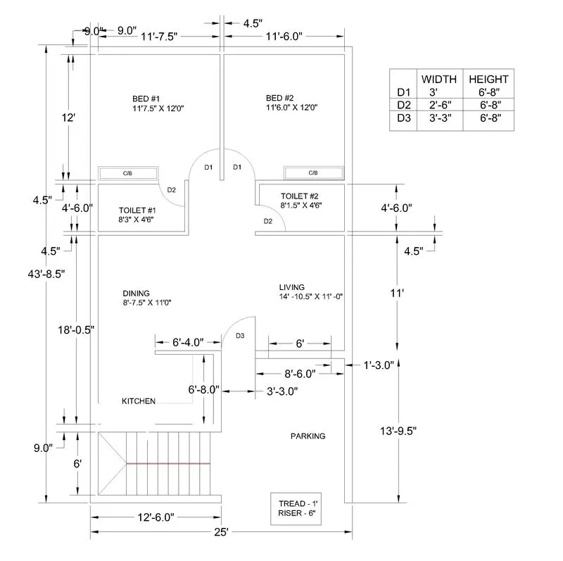
The aim is to sketch the layout of the residence using Autocad software.
INTRODUCTION :-
Autocad is a software which is used for drafting , designing , visualizations , drawing , sketching any plans or layout etc.It is consider as most important software tool for engineers.It is very handy software .It was first introduced in 1979 and the file format used in autocad is .dwg.
PROCEDURE :-
1. To draw the layout of the residence using Autocad software first step involves is to open Autocad software and select a setup from which select the engineering unit system as the given units are in feet and inches.
2. Then select the line tool and create a plan of 43'6.5" x 25' using the line tool.Then select any endpoint of the created plot and then create a line of 9.0" inside the plot in all the directions using line tool.
3. Now let's start to create from the stairs side so select the line tool and create a line of 12'6.0" from the left bottom and after creating that line trim the other lines so that the stairline must be clearly visible.
4.After that , draw a line 6' above the 9" wall line from the stair and again draw line of length 12'6.0" for the kitchen dimension. Dimension of 9" wall is included in the dimension of kitchen.
5.Then draw a line of length 6'8.0" above the 12'6.0" line excluding 9" line and then draw a line of length 4.5" in horizontal axis as thickness of wall dimension of 6'4.0" for kitchen.
6.Now for dining room , select line tool and take length of 18'0.5" from the kitchen inner wall and draw line of that length .
7. Then draw a line for 4.5" wall and after that draw a line of 4'6.0" for the Toilet dimension and then complete the sketching of toilet by creating line of8'3" for the other side dimension (L and B)
8.Now for Bedroom , draw the given dimension as 12' excluding 4.5" and 9" wall using same line tool. Apply the same procedure for other Bedroom of dimension 11'6.0" x 12'.
9. Use the same procedure for the sketching of the toilets as per the given dimensions.
10.Coming to the living room draw the given dimension of 11' length excluding the outer wall and after that draw a line of length 8'6.0" with 9.0" of wall thickness using the line tool.
11. Use the trim tool wherever it is needed to trim the sketch.
12. Now for parking area draw a line of length 8'6" but first draw wall thickness of 9.0" and then draw the parking area using line tool as given length .
13.After completing the sketch , we come to draw the doors of the sketeched plan of residential building. As given the dimensions Door D1 is of Width 3' . So we can draw a circle of radius 3' from end point as per the given figure and then trim the rest portion which is not required.
14. Same procedure applies for D2 and D3 which are of dimensions D2 = 2'3" and D3 = 3'3". So draw the circle as per the given with of the door as the radius of circle and then trim the portion which are not necessary.
15. Now coming to the stairs the given dimension of stairs with risers and treads as 6" and 1' . So draw the line from a point on the stair with length of 1' as treads . You can use different colours for the drawing of angle from platform also.
16. Now to add text in the drawn sketch we should use the text tool from the tool bar and write the required texts.
17. Use the dimension tool to dimension the drawn figure.
18.After that to plot the or print the drawn sketch we go to the plot option and then select the page setup and then preview the object which we have drawn.and then use the plot option to plot that drawn figure.
19. Save the figure if you want to save by pressing the Control + S button or directly from the save option.
RESULT :-
The drawn sketch is attached below :-
ANS 2.
AIM :-
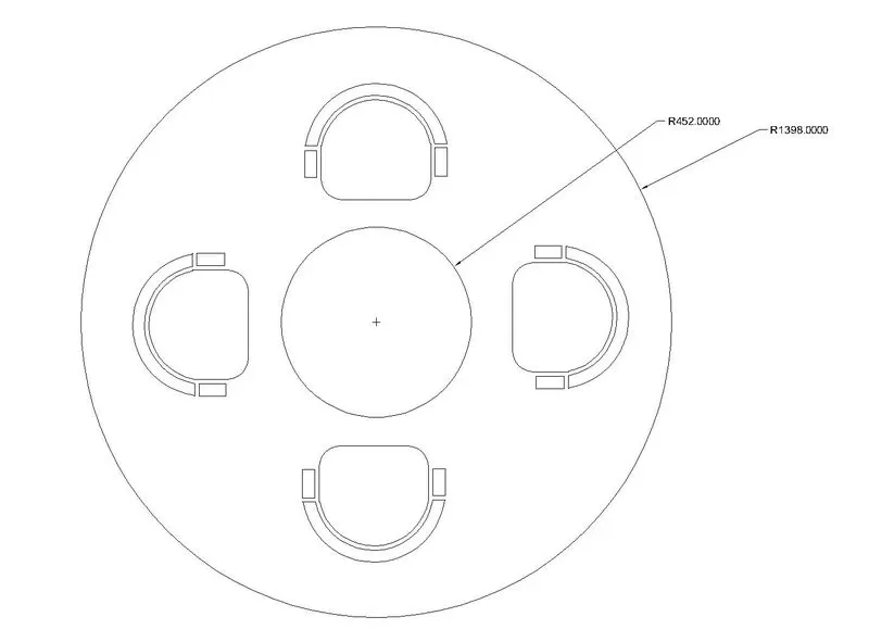
To sketch the seating plan for an outdoor canopy with the help of autocad software.
INTRODUCTION :-
Autocad is a software which is used for drafting , designing , visualizations , drawing , sketching any plans or layout etc.It is consider as most important software tool for engineers.It is very handy software .It was first introduced in 1979 and the file format used in autocad is .dwg.
PROCEDURE :-
1.Open autocad software and select a setup from wizard dailog box. Here we use Decimal unit system for sketching the given figure.
2.After that select circle tool and draw a circle of radius 1398 units from a random co ordinate .From the same centre again draw a circle or radius 452 units
3.After drawing circles, its time to draw the seatings and for that we need to assume the dimensions for creating the seating.
4.Draw a circle again of assumed radius and divide it in 4 equal parts using the line tool .Then trim the other half part of circle and also trim the lines that are drawn to divide the circle.
5.After that extend the end point of the circle or the left out arc using the line tool , here orthomode must be on and create lines as per the given seatout.
6.Now after that select the Fillet tool from the tool bar and select the first line and then give a radius of 200units .And specify the second point to get the desired filletting of the object .
7.After filletting is done , Again draw a circle by selecting the circlr tool from the tool bar and draw the circle from the centre point of previous circle and create a bigger circle than the previous one
8.Repeat the same procedure to draw a circle again from the previous circle centre point.
9.After that trim the other portions of the circle which are not neccessary for the given figure using trim tool.
10.Draw two rectangles above and below the seatout as given in the figure.The dimensions of the rectangle is 80 x 80 units.
11.After then select the seatout and type copy from the command bar or simply select the copy tool from the tool bar and copy the seat out created.
12. Copy the seat out 4times and then use the rotate tool to rotate the sit out as per the given figure.
13. After rotating the seat out created , select them and use the move command to move the created figure and move them to the required space.
14. Now use that dimension tool to dimension the created figure. You can also use the dimrad two dimension the radius of circle.
15.After that to plot the or print the drawn sketch we go to the plot option and then select the page setup and then preview the object which we have drawn.and then use the plot option to plot that drawn figure.
16.Save the figure if you want to save by pressing the Control + S button or directly from the save option.
RESULT :-
Created Seating plan is attached below :-
ANS 3.
AIM :-
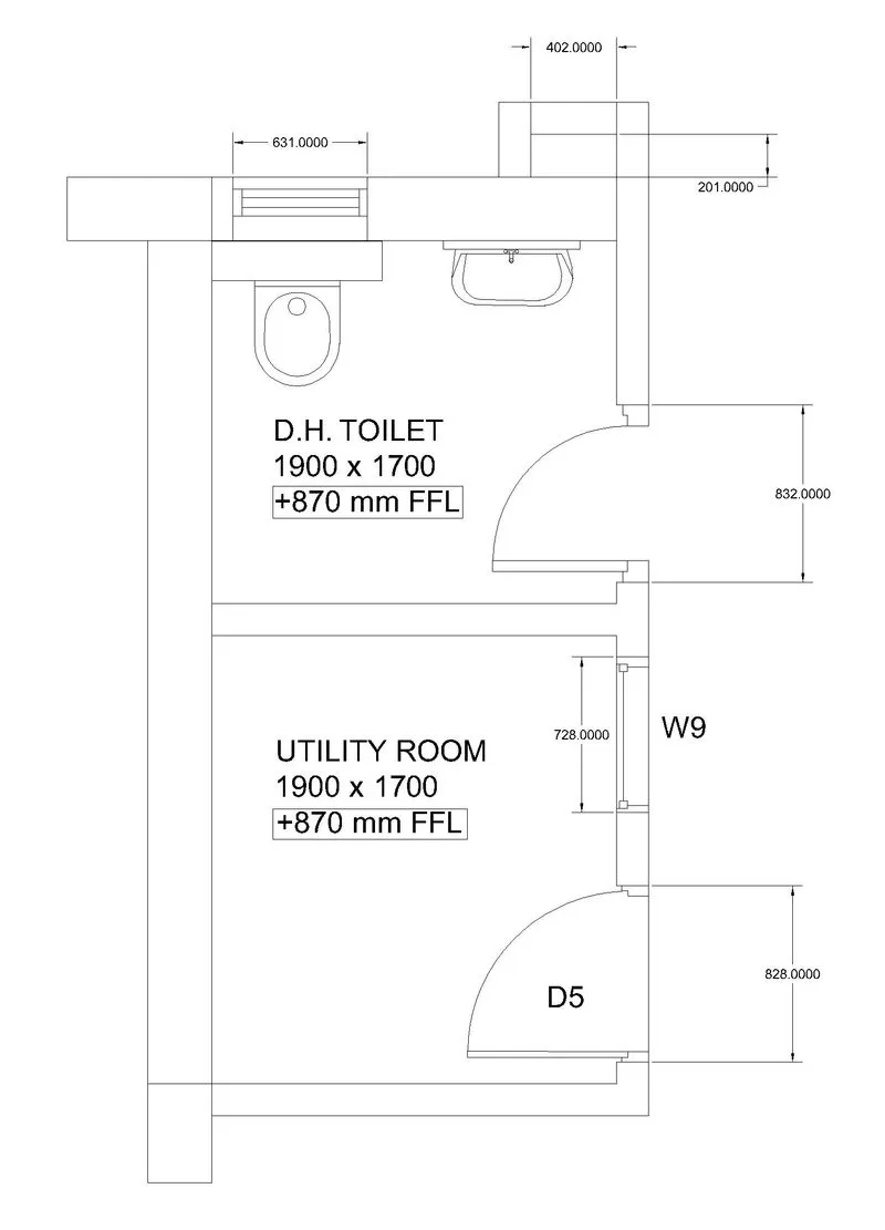
To Sketch the part plan for the toilets and utilities room.
INTRODUCTION :-
Autocad is a software which is used for drafting , designing , visualizations , drawing , sketching any plans or layout etc.It is consider as most important software tool for engineers.It is very handy software .It was first introduced in 1979 and the file format used in autocad is .dwg.
PROCEDURE :-
1.Open autocad software and select a setup from wizard dailog box. Here we use Decimal unit system for sketching the given figure.
2.Then select the line tool from the tool bar and draw a line of 4400 units in Y axis using any random coordinate.
3.Continue the line command and draw a line of 2350units in x axis using the line tool and complete the closed figure again by drawing line of 4400 units in Y axis and then again drawing line of 2350 units in x axis.
4.After that we need to the inner and outer wall surfaces which are of length 150 and 300 mm units.So, as per the given figure , by using the line tool , we start drawing the outer walls of 300mm from top left point and hence, completing the required figure.
5.Then,for creating doors and windows ,we use the given length , So for Doors the length given is 828 units and 832 units .From lower right bottom , draw a line of 100mm for the door attachments using the line tool with width of 150mm .
6.Now after that draw line of 828 units from the Y axis point and 150 units of line is drawn in left x axis from that point.After that join the points and use trim tool to make it accurate.
7.Then comes the window portion.So from the other wall take a point and draw a line of 100 units and then draw 150 units in x axis and complete the figure by closing it.
8.After that draw a line of 728 units for the window in Y axis and then 150 unit in downward left x axis. Complete the figure by joining them with Snap cursor mode on and endpoint on .
9.For door of length 832 units follow the same procedure as step no.6 as per the given figure.
10.Now from the top right portion ,select line tool and draw a line of length 201 units in upward y axis and then draw a wall unit of 150units in Y axis and then 150units in X axis .
11.Then draw a line of 402 units by using line tool with width of 150mm units in x and y axis respectively and close the figure .
12.Use Trim tool wherever it is necessary to trim the drawn object or figure and hence, desired figure can be obtained.
13.After that use the dimension tool from the dimension tool bar to dimension the figure , before plotting anf saving.
14.After that to plot the or print the drawn sketch we go to the plot option and then select the page setup and then preview the object which we have drawn.and then use the plot option to plot that drawn figure.
15.Save the figure if you want to save by pressing the Control + S button or directly from the save option..
RESULT :-
Drawn figure is attached below :-