Creating Levels, Grids, Layout and model elements for a residential unit using REVIT
QUESTION-1
BIM
- BIM is an acronym for building information modelling or building information management. It is highly collaborative process that allows architects, engineers, real estate developers, contractors, manufacturers and other construction professionals to plan, design and construct a structure or building within one 3D model.
FEATURES OF BIM:
- Coordination Feature: The Revit as BIM tool helps in coordination between multiple disciplines. The different disciplines can come together and work on a single project as well as they have their independant design unit but they can, coordinate in achieving progress in a project as a whole unit so the revit offer this coordination which is a key feature in Building Information Modelling.
- Computation Feature: The Revit as BIM tool helps in performing computation such as material schedule or quantity schedule or to evaluate the energy analysis.
BENEFITS OF USING BIM over 2D CAD Tools:
- While there are parallels between CAD and BIM, they are two very different things. CAD deals almost exclusively with the process of designing models and floorplans. That's an important part of BIM as well, but BIM includes so much more than designs. BIM is a methodology that entire firm needs to accept any chance of succeeding in its use.
- A major difference between BIM and CAD is the interactivity of the different dimensions during the editing process. In BIM, the dimensions that needs to be made in a building design, such as the width of a wall or corridor, can be done in a single edit.
- The great efficiency of using a BIM software means that the designer can concentrate more on the creativity aspects of a project without having to constantly worry about updating a multitude of line entities throughout the entire project. This translates into an incredible increase in productivity because each object, chosen from a BIM objects menu, already comes with a set of pre-defined information that can provide useful data for calculating project cost, leads to a considerable saving of time.
- Within a BIM design procedure, floor plans, elevation views and section views are simply different views of the same object. All views can be observed according to specific design phases. Whenever there's a change somewhere in the project, these changes seamlessly affect all other related documents.
- As an example, by simply chaning the external finish of a facade element, this causes a modification in the wall's transmittance value, its cost and even its structural load. This allows the technician to avoid mistakes and be sure to have all darwings aligned with the latest project revisions wherever and whenever they are introduced.
QUESTION-2:
AIM: To understand the concept of categories, families, elements, instances in revit and to create the family.
CATEGORY:
- Categories are group of elements having common properties.
- It is predefined by the software.
- Eg- A wall or door is an example of category.
- We can insert element of our choice and create a category.
- It controls the organization, visibility, graphical representation and scheduling options of the family within the project.
FAMILY:
- It is different elements having same properties
- Eg: Single flush door - It has different sizes having the same property.
- Family is a grouping of 2D or 3D information that serves to represent a discrete building or documentation element in the project.
- It defines parametric, graphical and documentation requirements.
ELEMENTS:
- Element is the basic feature which cannot be subdivided.
- Eg: Single flush door, the different sizes represent the element.
- Single flush door of size 30"X80", 30"X84"
- Element is a specific representation in a family defined by distinct parametric, graphical and documentation characteristics which make it unique from other types in the family.
INSTANCE:
- It is an individual representation of a type in the project defined by unique parametric , graphical and documentation characteristics which make it unique from other instances in the project.
Examples:
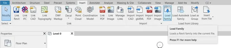
- Go to insert tab

- Click Load Family
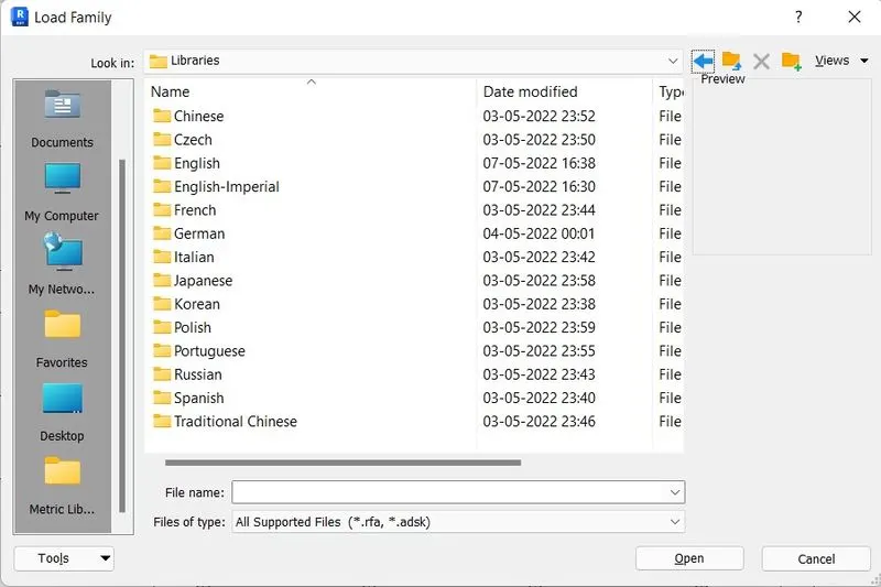
- Choose US and select English Imperial
- Select DOORS
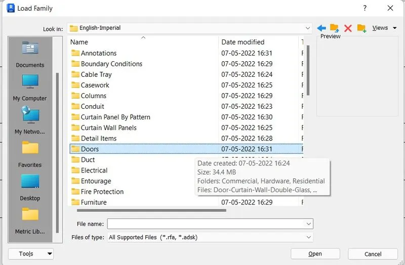
- Click Open and insert this door in your current project.
QUESTION-3:
AIM: To use the manage toolbar to enter project setting. project name and project issue date.
PROCEDURE:
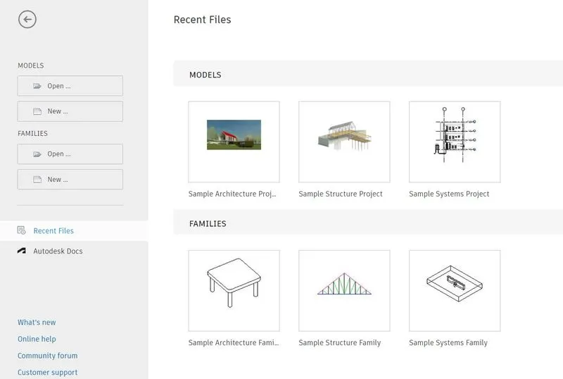
step-1: To open RVT 2023
step-2: To click new project
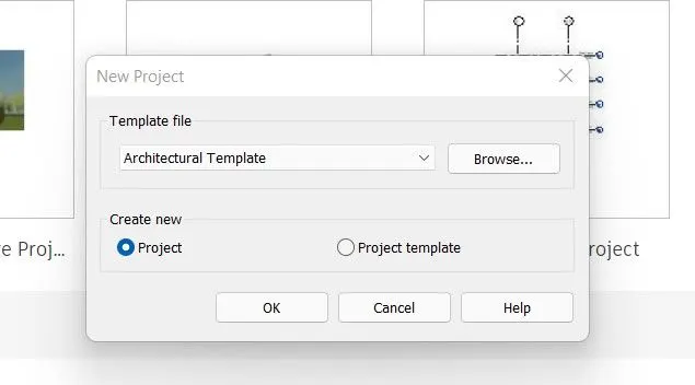
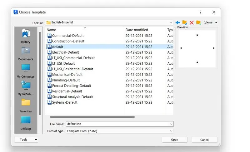
Step-3: Go to project information
step-4: Edit the information related to the current project.
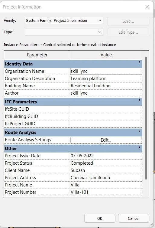
step-5: Select File tab
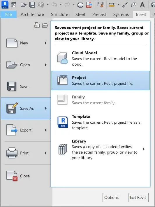
step-6: Select Save as and select project tab
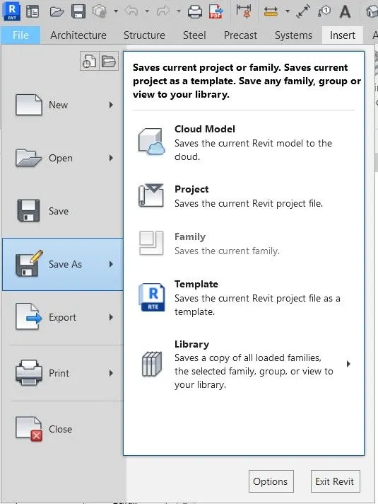
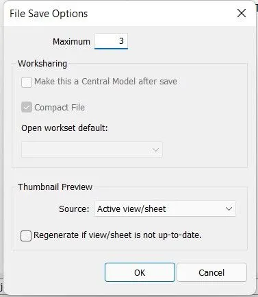
step-7: Go to option and select 3 backups and click ok.
QUESTION-4:
AIM: To create levels and grids from given dimensions.
PROCEDURE:
step-1: Open RVT 2023
step-2: Select New project
step-3: Select the template you want to draw.
step-4: Go to Project browser
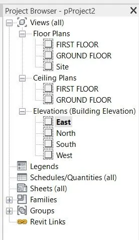
step-5: Select Elevation levels like East or west
step-6: Go to Architecture tab
step-7: Select Levels
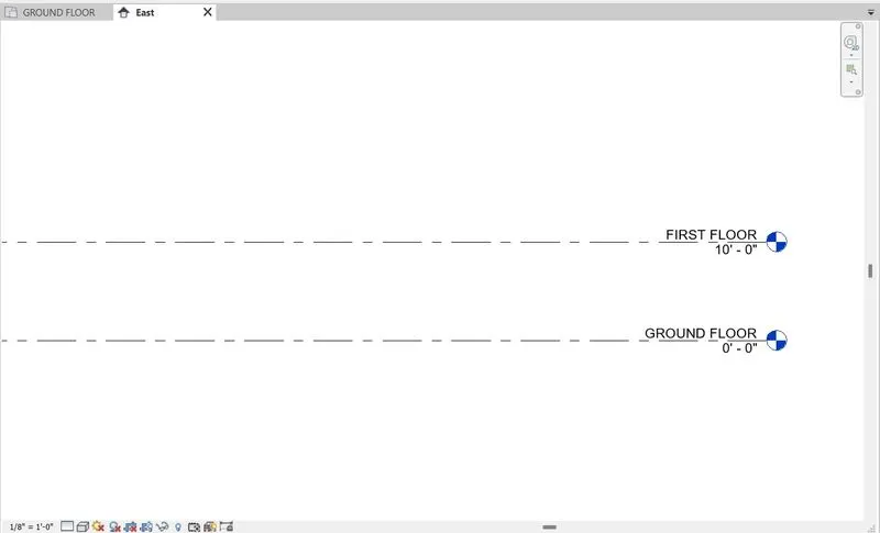
step-8: Here it shows pre-drafted two levels
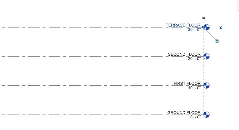
step-9: Double click it to change their name as per our convenience
step-10: Select Pickline option in the ribbon

step-11: Enter offset value
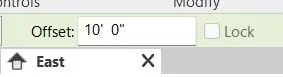
step-12: Select existing level and to draw new level with the base of previous line.
step-13: Repeat the same step as many levels you want.
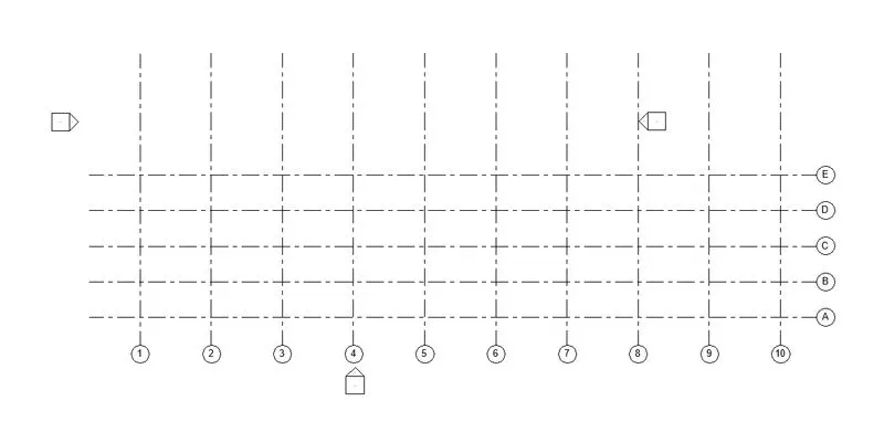
GRIDS:
step-1: Select Ground floor plan in project browser
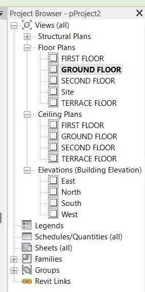
step-2: select Grids in Architecture tab

step-3:
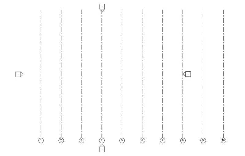
step-4:
RESULT:
LEVELS:
GRIDS:
QUESTION-5:
AIM: To create 3D modelling residential unit.
PROCEDURE:
step-1: Open RVT 2023
step-2: Select New
step-3: Select project template
step-4: Go to project browser
step-5: Select Elevation
step-6: Create the levels
step-7: Go to project brower
step-8: Select Floor layout
step-9: Select Grid in architectural tab
step-10: Create a grid with the required spacing
step-11: Select pickline with specific offset to create remaining grids
step-12: Select Wall from Architectural tab
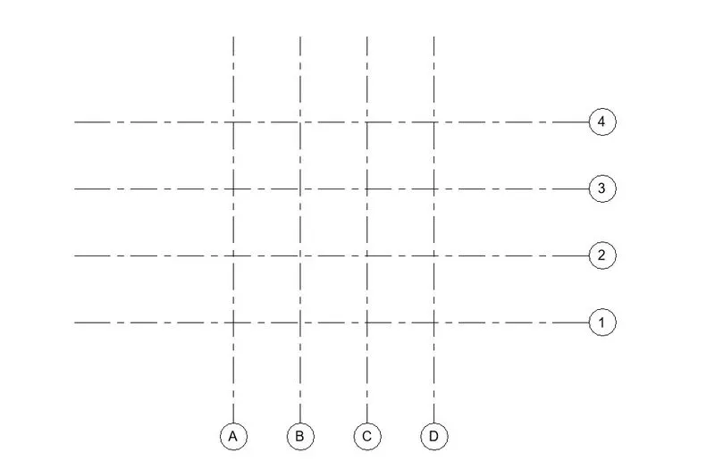
step-13: Draw Architectural wall on the Grids
step-14: Create a Ground floor plan
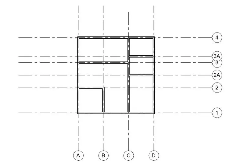
step-15: Select 3D view from view tab
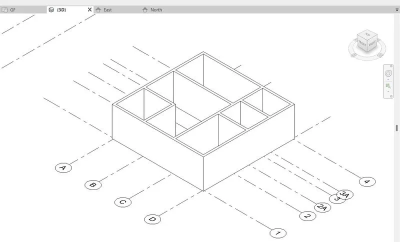
step-16: Select Realistic view
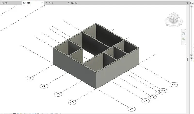
RESULT:
QUESTION-6:
AIM: To Add dimensions for a residential plan we create in the previous question.
PROCEDURE:
step-1: Go to Annotation tab
step-2: Select Aligned dimenion tool
step-3: Select the points to mark dimensions
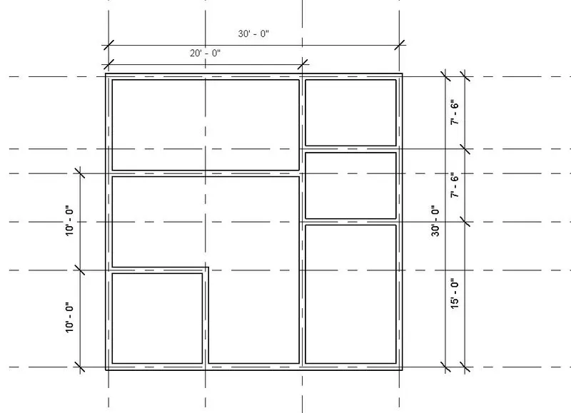
step-4: Select Text tool to notify room titles
step-5: Select COPY tool to copy the titleblock and paste it into other rooms as well
step-6: Double click the text and modify
step-7: Go to Insert tab
step-8: Select Load family
step-9: Select Door from library
step-10: Insert in the floor layout
step-11: Again Go to Insert tab
step-12: Select load family
step-13: Select Windows from library
step-14: Insert the windows wherever it required.
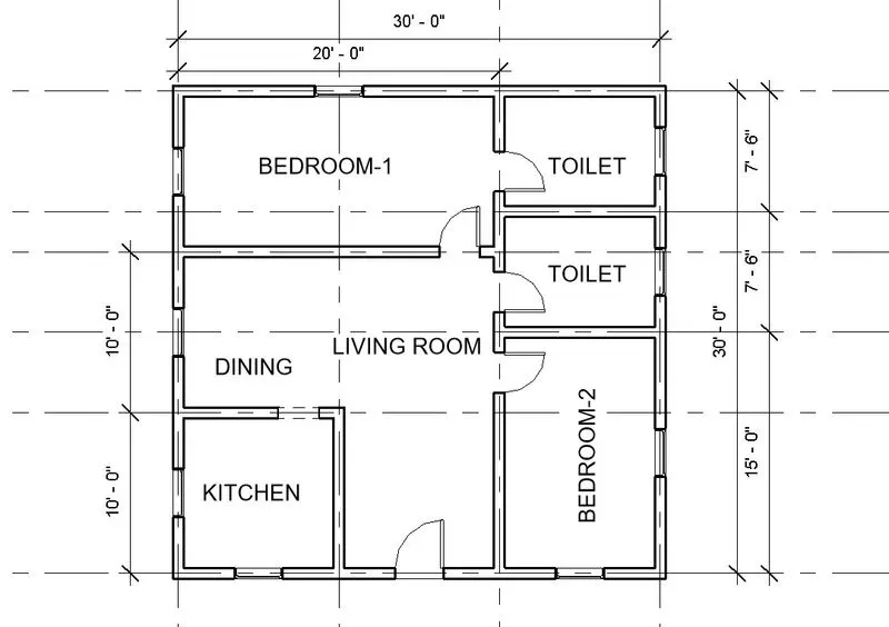
step-15: Select Floor from Architectural tab
step-16: Select boundary walls to create floor
step-17: Select shaded view to show.
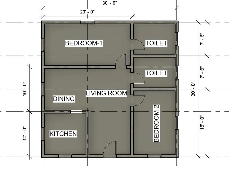
step-18: Select 3D view from view tab
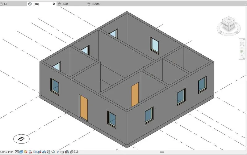
step-19: Select Window and change the window model.
step-20: Select 3D view
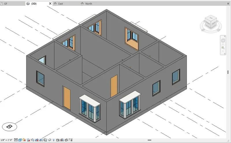
RESULT:
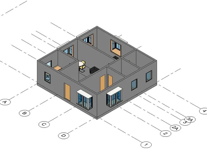
QUESTION-7
AIM: To add elements such as doors, windows, bed, furnitures, couch, dining table in the residential unit.
PROCEDURE:
step-1: Go to insert tab
step-2: Select Load family
step-3: Select US
step-4: Select English Imperial
step-5: Select Furniture folder
step-6: Select the furniture
step-7: Insert the selected furniture to the layout
step-8: In the same way insert the all other required things in the layout
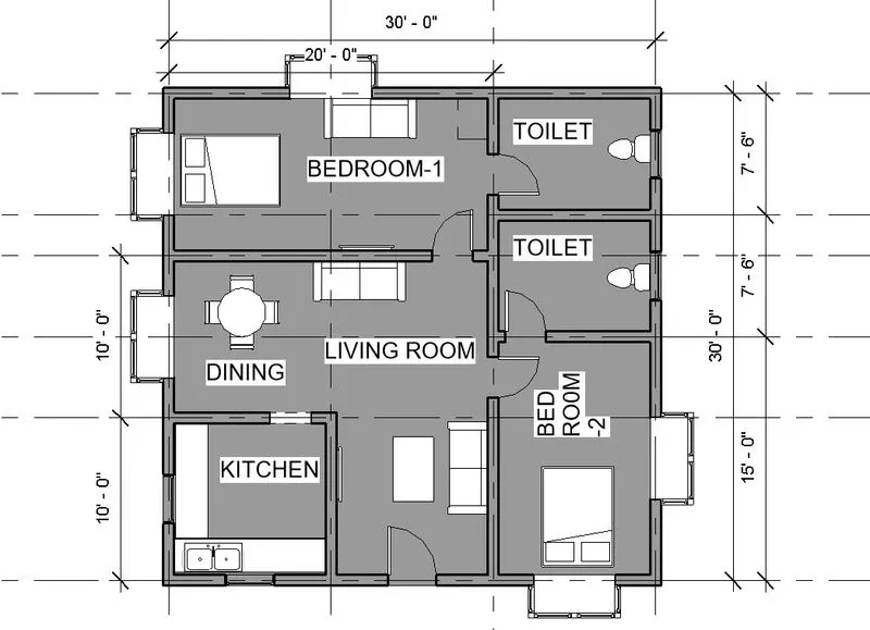
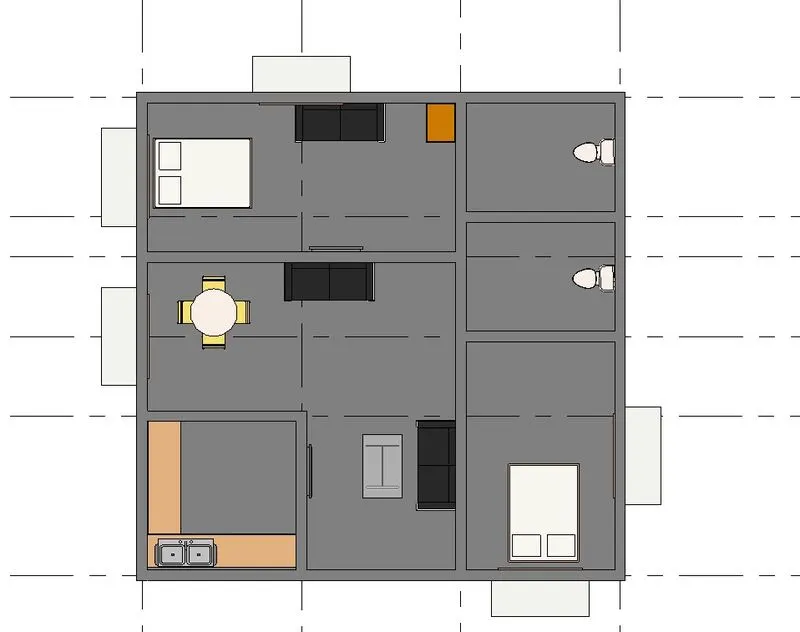
step-9: Select 3D view
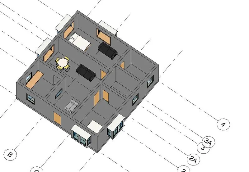
RESULT: