Drafting of various geometries using Chamfer, Fillet tool in AutoCad
AIM:
To drafting of various geometrics using chamfer, fillet tool in Auto CAD.
INTRODUCTION:
AutoCAD has numerous drawing and modification tools. Among those below tools are used vast area of drawing.
These are,
Chamfer:
- An angled line that meets the end points of two straight 2D points.
- A sloped transition between two surfaces or adjacent faces on 3D solid.
- The distance and angles that we specify are applied in the order that we select the objects.
Fillet:
- An arc that is created as tangent between two 2D objects.
- A curved transition between two surfaces or adjacent faces on a 3D solid.
Offset:
- It is used to create concentric circles, parallel lines and parallel curves by selecting objects
- We can offset an object at a specified distance or through a point.
Object snap:
- OSNAP provide a way specify precise locations, such as end-point, mid-point, center, etc., on objects whenever we are prompted for a point within a command.
Rotate:
- This tool helps to rotate objects with respect to specified point.
- This happen by entering angle of rotation or zero angle.
Mirror:
- It helps to mirror the image we required.
- Select the drawing which want to mirror, and use mirror command to create a copy of this object with mirrored position.
1. Drawing -1:
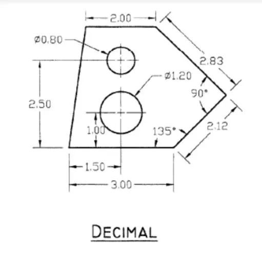
AIM: To draft given geometry using decimal units.
INTRODUCTION:
Line: Specify the starting point of the line by clicking mouse then will be prompted to specify the second point. It can be used for making simple lines in the drawing.
Circle: It is the command used for making a circle in the drawing sheet. By entering "C" to envoke this tool.
Dimlinear: To measure linear dimensions of all drawing elements.
Dimaligned: It helps to measure aligned elements. "DIMALI" helps to envoke the tool.
Dimdiameter: It is used to measure diameter of circle.
Dimangular: It is used to measure angle of two elements
Text: Single line text and multi line text helps to write notes in the drawing for future reference.
PROCEDURE:
step-1: Go to Open new drawing sheet.
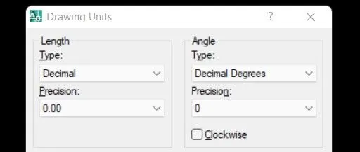
step-2: Type "UN" command to open a dialogue box of units. Over there we change units into "Decimal" and select the precision we required, here i select '0.00'.
step-3: Type "LIMITS" command to set a limit of drawing sheet. when you enter limits, the command line asking left lower corner of the sheet, put 0,0 and press enter. Now command line asking right upper corner of sheet, we just put 100,100. We can choose maximum value which we needed to plot the diagram.

step-4: Than click enter to close the command.
step-5: Type "L" to envoke line tool to create the geometry we had.
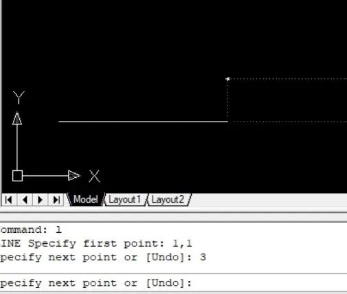
step-6: Specify the initial coordinate to create a line. "1,1"
step-7: Specify next point of 3 towards +ve X-direction.
step-8: Specify next point of @2.12<45
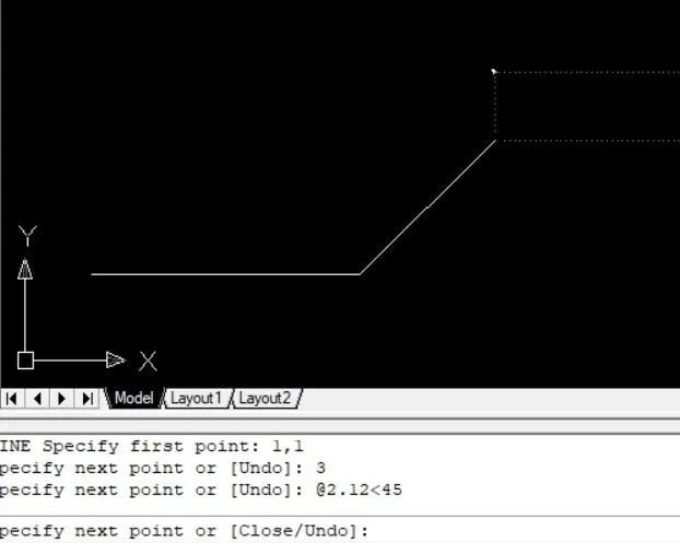
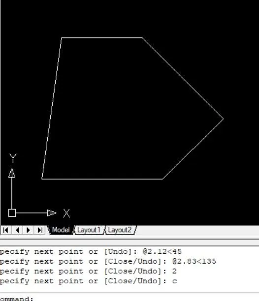
step-9: Specify next point of @2.83<135
step-10: Specify next point of 2 towards -ve X-direction.
Step-11: Click c to close the line tool where i start to complete outline of geometry.
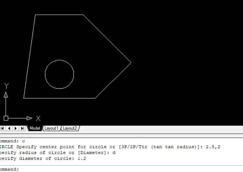
step-12: Type "C" to envoke circle tool
stpe-13: Mention 2.50,2 as a center of circle
Step-14: Click the center and put input as diameter
step-15: Give diameter of 1.2 than circle will plot.
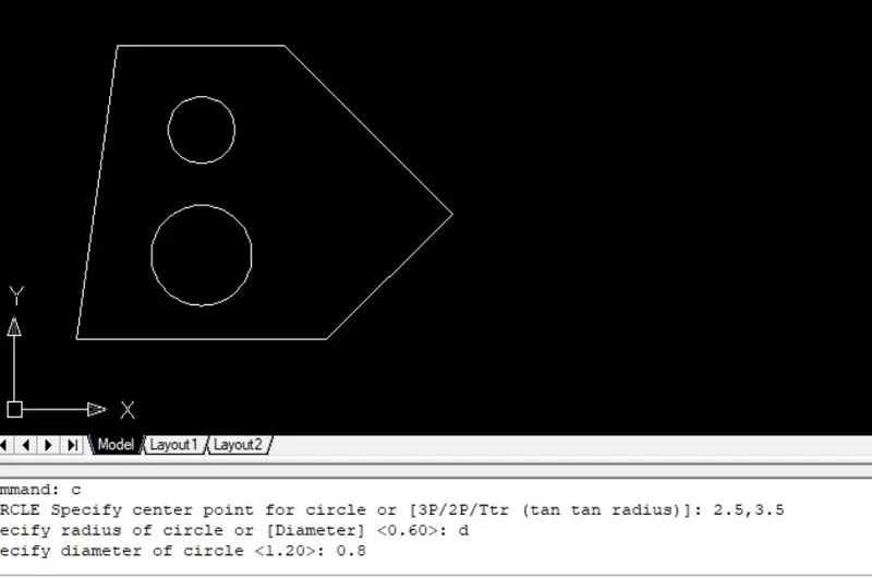
Step-16: Again enter "C" to envoke circle tool
stpe-17: Specify center point of circle is 2.5,3.5
step-18: Select diameter and give input of 0.8 to plot circle.
Step-19: Now marking all dimensions.
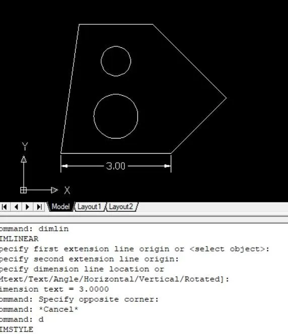
Step-20: Type "DIMLIN" to envoke linear dimension measurement tool
step-21: Click first point and end point to measured.
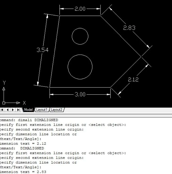
step-22: Type "DIMALI" for measuring aligned dimensions.
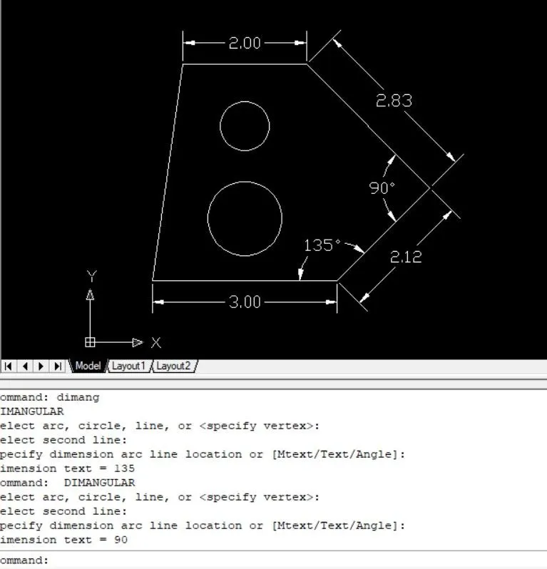
step-23: Type "DIMANG" to measure angle for alinged line to the linear line.
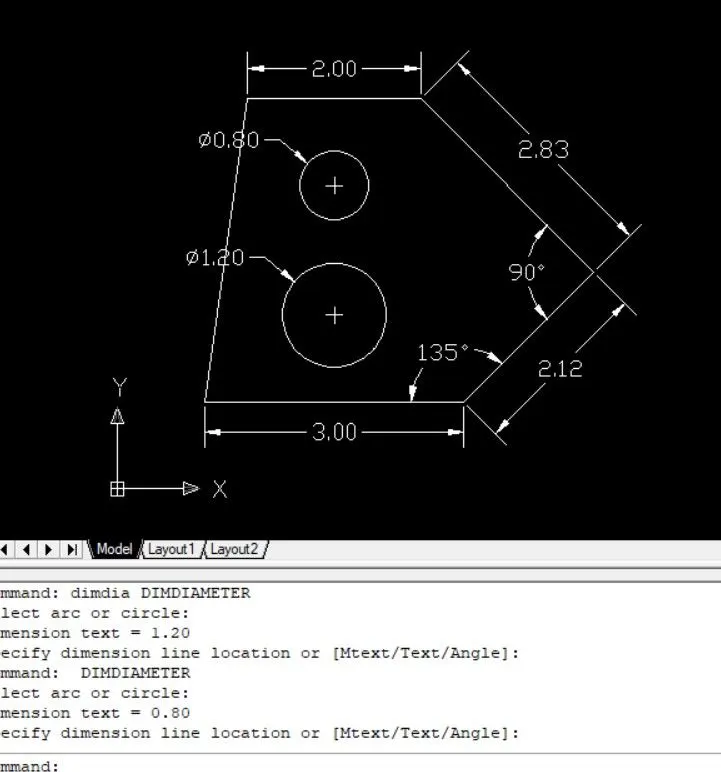
step-24: TYpe "DIMDIA" to measure and mark the diameter of circle for future reference.
stpe-25: If text of dimensions or arrow needed to change, use "D" to envoke dimension dialogue box to change all the styles to opt for the current sheet set.
step-26: In other cases, just select the dimensions and enter "CH" to envoke properties tab of dimensions we select, now required changes are modify for the single dimensions.
step-27: Use "MA" tool to match properties of the changed dimensions to all we need to change.
step-28: Use "DT" tool to type "DECIMAL" in the drawing sheet.
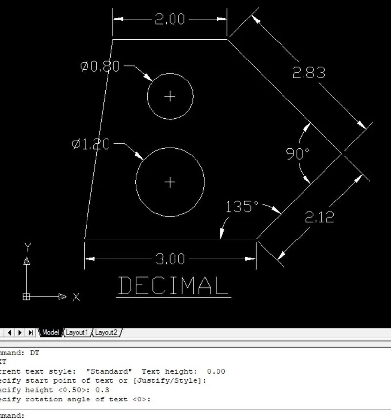
RESULT:
- Here is the final output of given geometry by using AutoCAD.
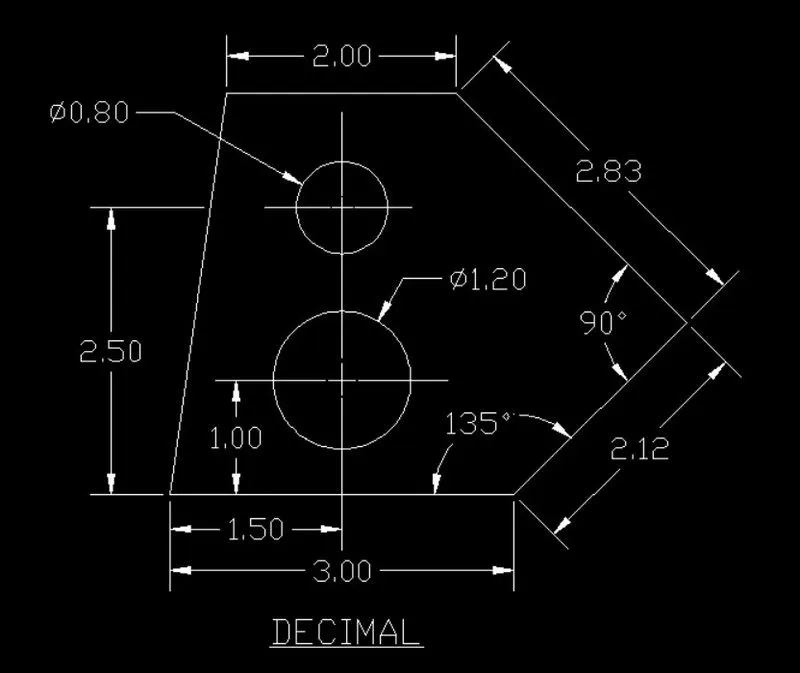
2. Drawing-2:
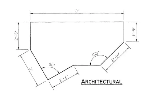
AIM: To draft given geometry using Architectural units.
INTRODUCTION:
Line: Specify the starting point of the line by clicking mouse then will be prompted to specify the second point. It can be used for making simple lines in the drawing.
Dimlinear: To measure linear dimensions of all drawing elements.
Dimaligned: It helps to measure aligned elements. "DIMALI" helps to envoke the tool.
Dimdiameter: It is used to measure diameter of circle.
Dimangular: It is used to measure angle of two elements
Text: Single line text and multi line text helps to write notes in the drawing for future reference.
PROCEDURE:
step-1: Go to Open new drawing sheet.
step-2: Type "UN" command to open a dialogue box of units. Over there we change units into "Architectural" and select the precision we required, here i select 0'00".
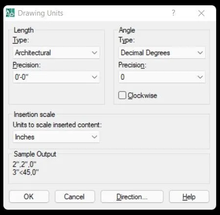
step-3: Type "LIMITS" command to set a limit of drawing sheet. when you enter limits, the command line asking left lower corner of the sheet, put 0,0 and press enter. Now command line asking right upper corner of sheet, we just put 100,100. We can choose maximum value which we needed to plot the diagram.
step-4: Than click enter to close the command.
step-5: Type "L" to envoke line tool to create the geometry we had.
step-6: To plot initial point for clicking cursor in to sheet.
step-7: Specify next point of 2'5" towards +ve Y-direction.
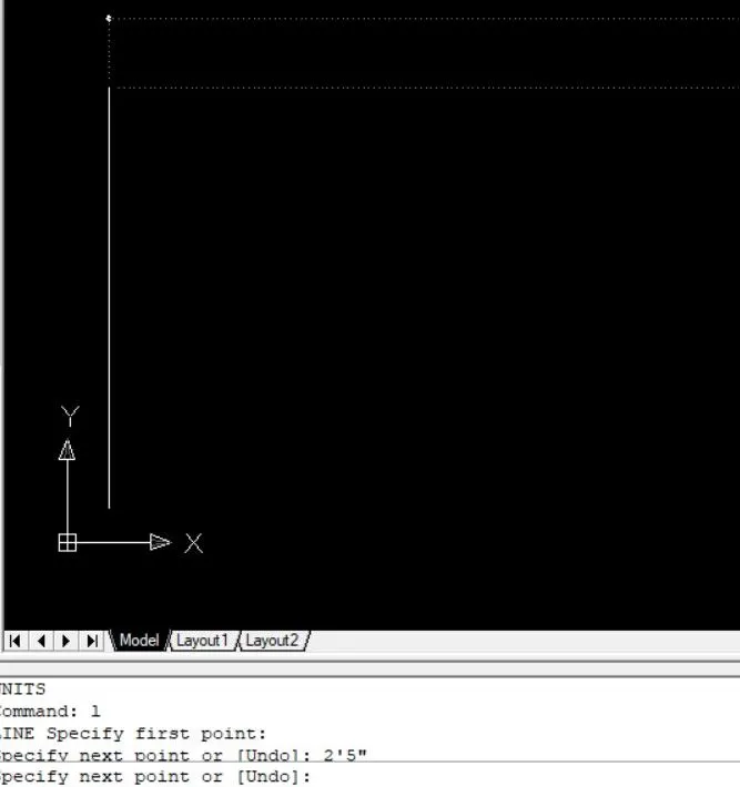
step-8: Specify next point of 8' towards +ve X-direction.
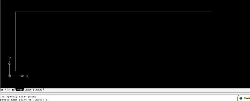
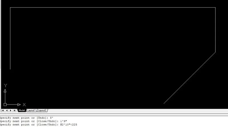
step-9: Specify next point of 1'9" towards -ve Y-direction.
step-10: Specify next point of @2'10"<225
step-11: Click enter to close the tool.
step-12: Type "L" to envoke line tool and select initial point
stpe-13: Specify next point of @3'<300
step-14: Specify next point of @2'6"<30
step-15: Select previous end to close the line.
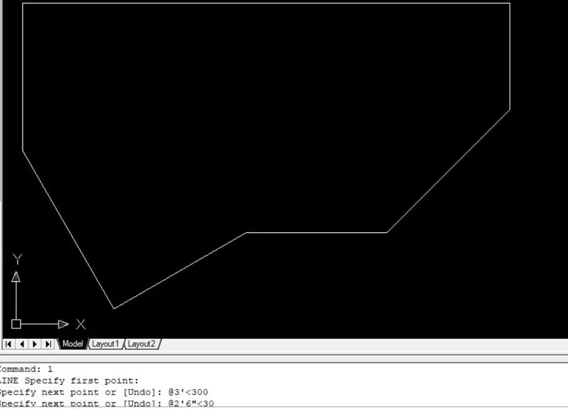
step-16: Type "DIMALI" to measure all the aligned and linear dimensions of the geometry.
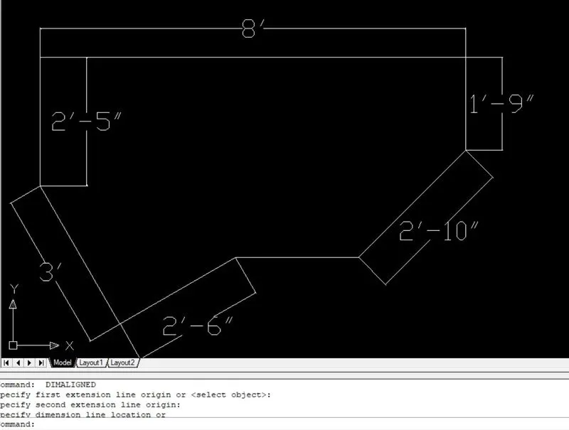
step-17: Type "DIMANG" to measure all the angles of the geometry.
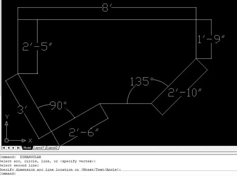
step-18: Type "DT" to envoke text tool to mention "ARCHITEXTURAL" in the drawing.
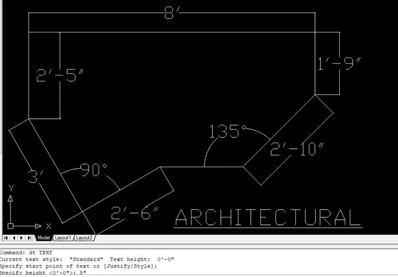
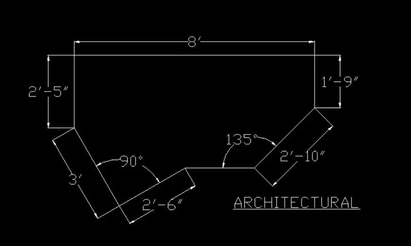
RESULT:
- Here is the final output of given geometry by using AutoCAD.
3. Drawing-3:
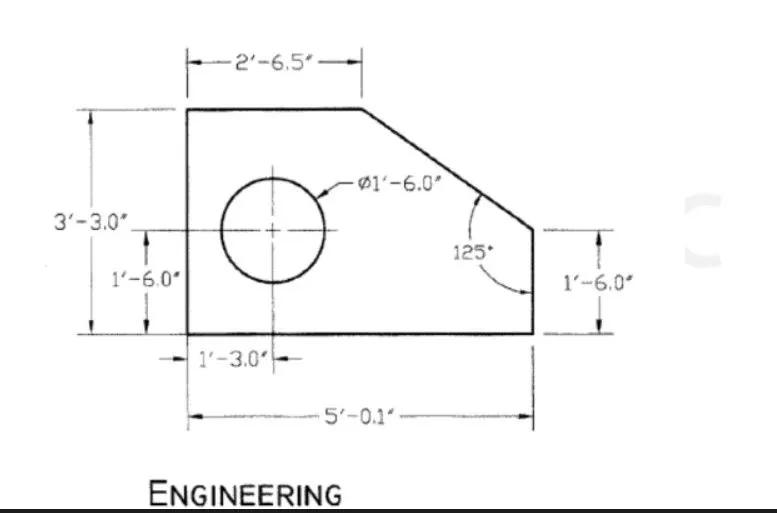
AIM: To draft given geometry using Architectural units.
INTRODUCTION:
Line: Specify the starting point of the line by clicking mouse then will be prompted to specify the second point. It can be used for making simple lines in the drawing.
Circle: It is the command used for making a circle in the drawing sheet. By entering "C" to envoke this tool.
Dimlinear: To measure linear dimensions of all drawing elements.
Dimaligned: It helps to measure aligned elements. "DIMALI" helps to envoke the tool.
Dimdiameter: It is used to measure diameter of circle.
Dimangular: It is used to measure angle of two elements
Text: Single line text and multi line text helps to write notes in the drawing for future reference.
PROCEDURE:
step-1: Go to Open new drawing sheet.
step-2: Type "UN" command to open a dialogue box of units. Over there we change units into "Engineering" and select the precision we required, here i select 0'-0.0".
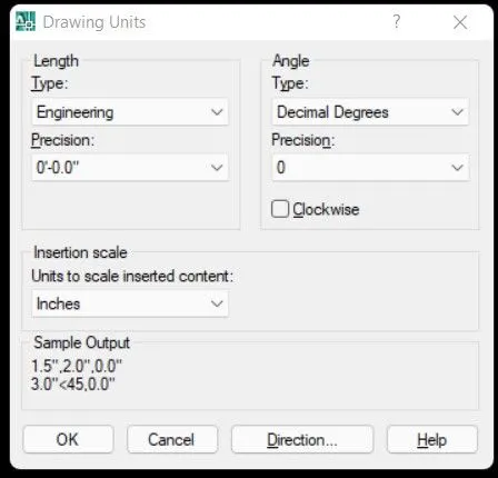
step-3: Type "LIMITS" command to set a limit of drawing sheet. when you enter limits, the command line asking left lower corner of the sheet, put 0,0 and press enter. Now command line asking right upper corner of sheet, we just put 100,100. We can choose maximum value which we needed to plot the diagram.

step-4: Than click enter to close the command.
step-5: Type "L" to envoke line tool to create the geometry we had.
step-6: Specify initial point 5',5'.
step-7: Specify next point of 2'6.5" towards -ve X-direction.
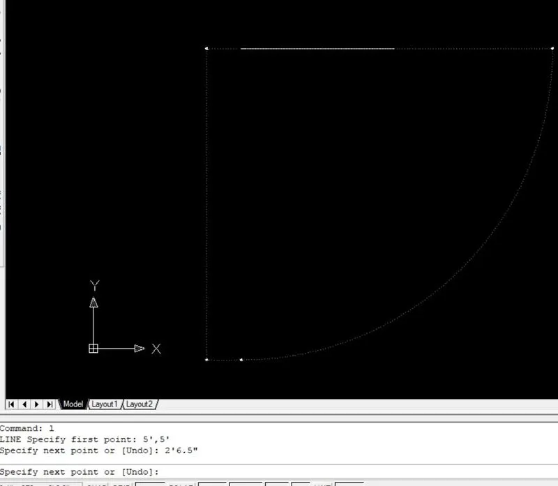
step-8: Specify next point of 3'3" towards -ve Y-direction
step-9: specify next point of 5'0.1" towards +ve X-direction
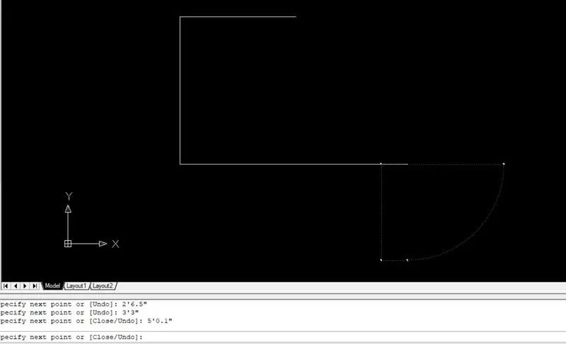
step-10: Specify next point of 1'6" towards +ve Y-direction.
step-11: Type C close where we initiate the drawing.
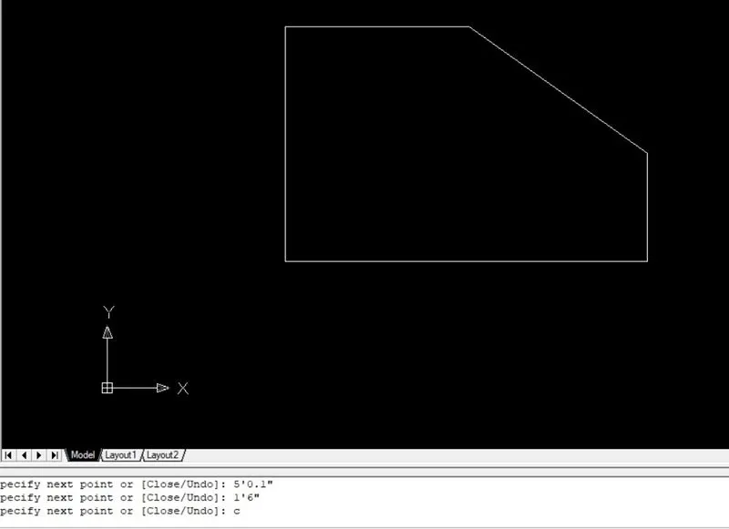
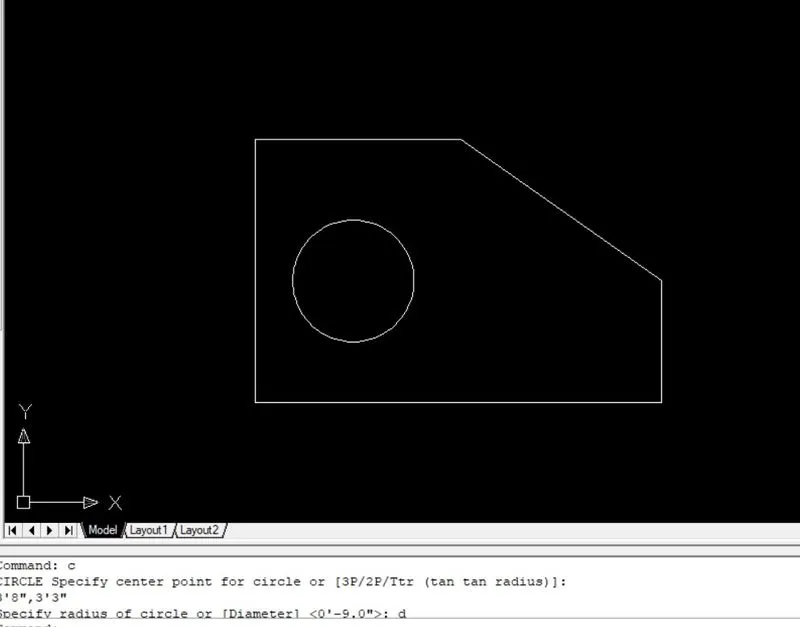
step-12: Type "C" to envoke circle tool to plot centre point of circle
step-13: Type center point as 3'3",3'8.5"
step-14: Select diameter from command line and give input of 1'6" as a diameter of circle.
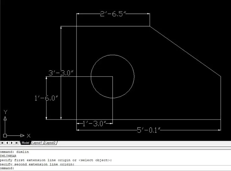
step-15: Type "DIMLIN" to measure all the dimensions of linear elements.
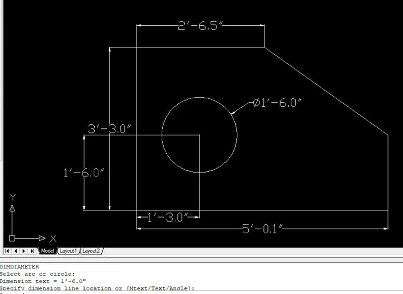
step-16: Type "DIMDIA" to measure diameter of the circle.
step-17: Type "DIMANG" to measure the angle between linear to aligned element.
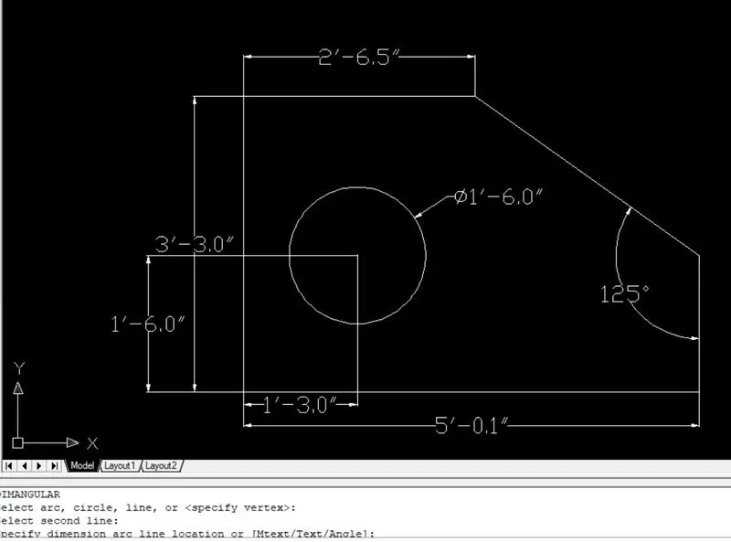
step-18: Type "DT" to envoke text tool to write "ENGINEERING" in the drawing.
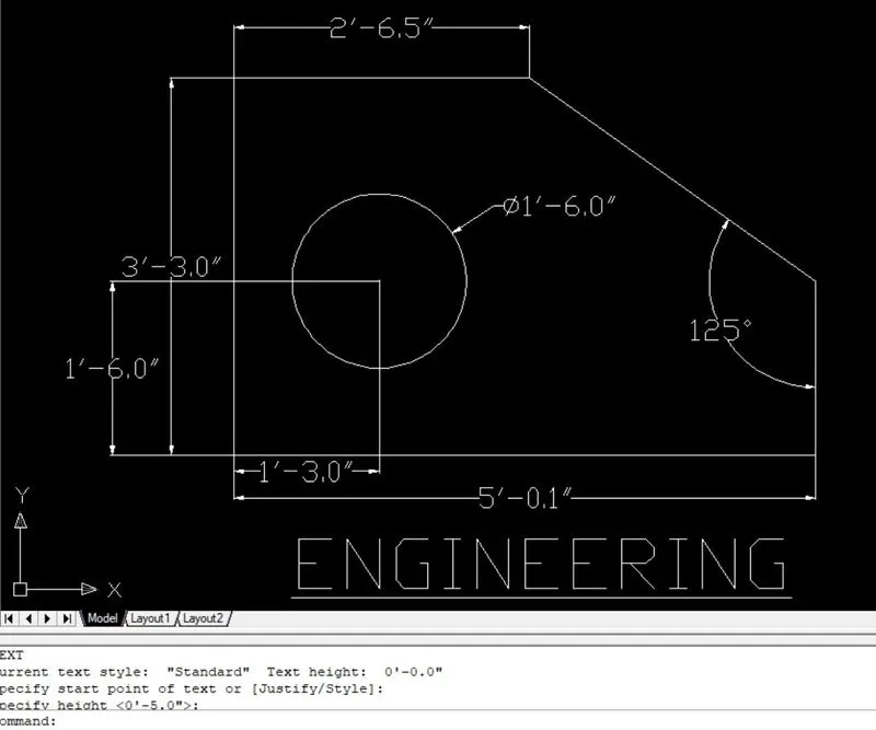
step-19: Press enter to close the tool.
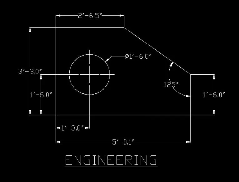
RESULT:
- Here is the final output of given geometry by using AutoCAD.
4. Drawing-4:
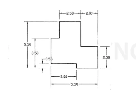
AIM: To draft given geometry using decimal units.
INTRODUCTION:
Line: Specify the starting point of the line by clicking mouse then will be prompted to specify the second point. It can be used for making simple lines in the drawing.
Dimlinear: To measure linear dimensions of all drawing elements.
Text: Single line text and multi line text helps to write notes in the drawing for future reference.
PROCEDURE:
step-1: Go to Open new drawing sheet.
step-2: Type "UN" command to open a dialogue box of units. Over there we change units into "Decimal" and select the precision we required, here i select '0.00'.
step-3: Type "LIMITS" command to set a limit of drawing sheet. when you enter limits, the command line asking left lower corner of the sheet, put 0,0 and press enter. Now command line asking right upper corner of sheet, we just put 100,100. We can choose maximum value which we needed to plot the diagram.
step-4: Than click enter to close the command.
step-5: Type "L" to envoke line tool to create the geometry we had.
step-6: Specify the initial coordinate to create a line. "1,1"
step-7:Specify next point of 3 towards +ve X-direction.
step-8: Specify next point of 0.5 towards -ve Y-direction
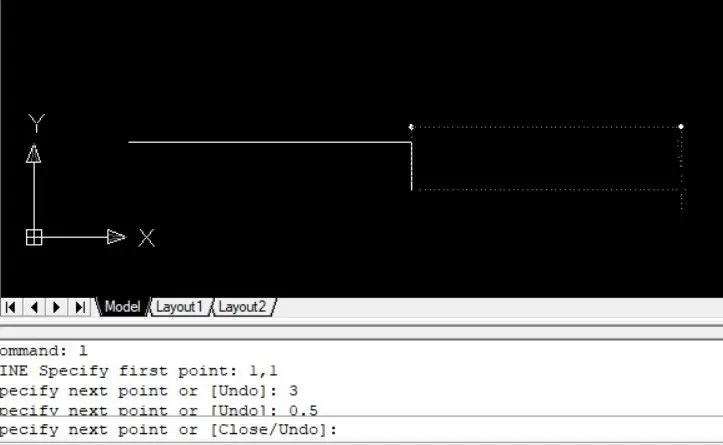
step-9:Specify next point of 2.5 towards +ve X-direction.
step-10: Specify next point of 2.5 towards +ve Y-direction
step-11:Specify next point of 2.0 towards -ve X-direction.
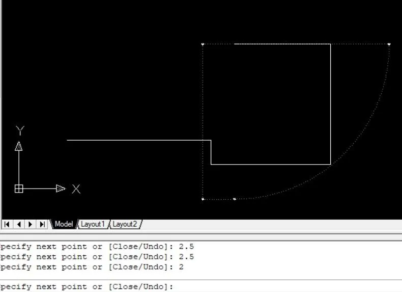
step-12: Specify next point of 3 towards +ve Y-direction
step-13:Specify next point of 2.5 towards -ve X-direction.
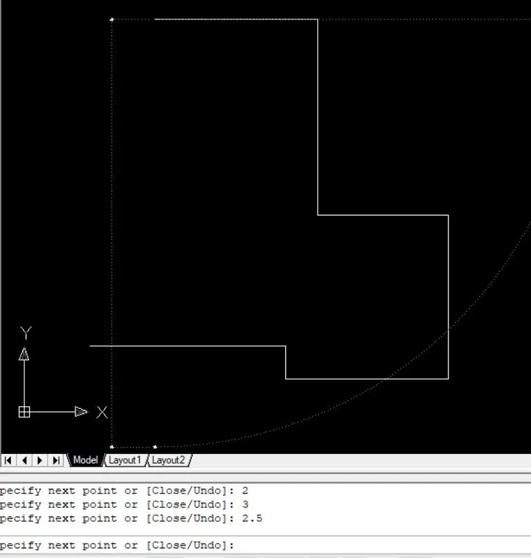
step-14: Specify next point of 2 towards -ve Y-direction
step-15:Specify next point of 1 towards -ve X-direction.
step-16: Type C to close the line tool.
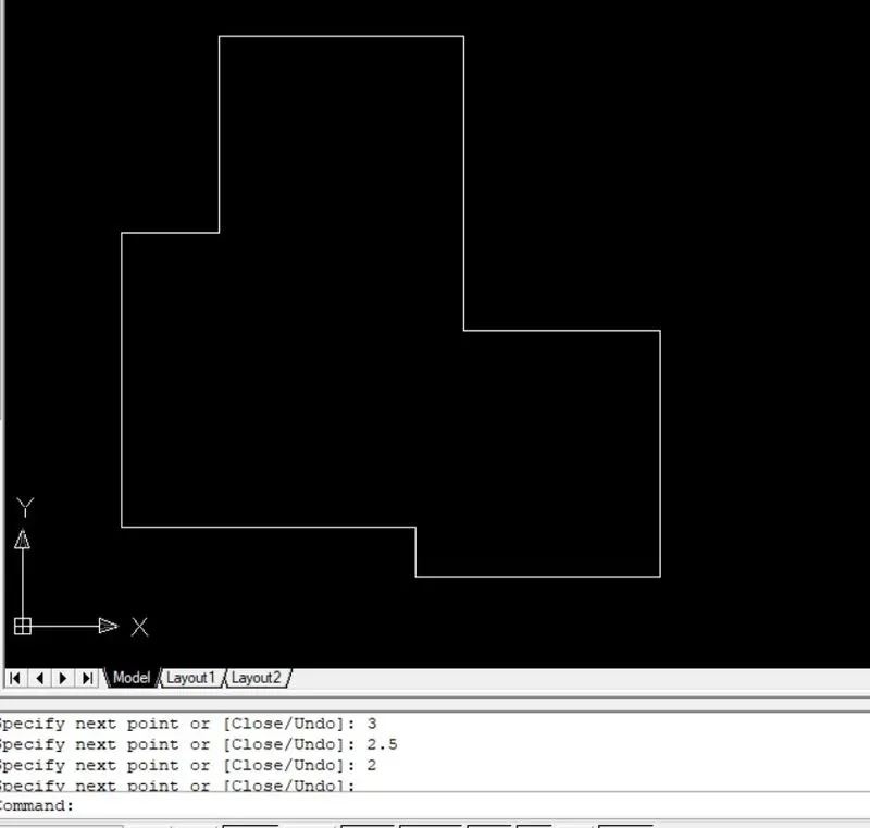
step-17: Type "DIMLIN" tool to measure linear dimensions.
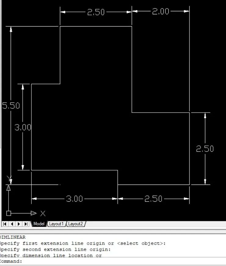
RESULT:
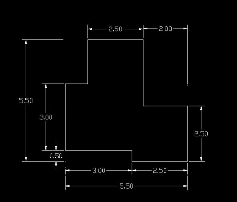
- Here is the final output of given geometry by using AutoCAD.
5. Drawing-5:
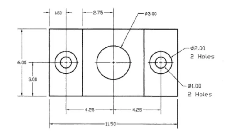
AIM: To draft given geometry using decimal units.
INTRODUCTION:
Line: Specify the starting point of the line by clicking mouse then will be prompted to specify the second point. It can be used for making simple lines in the drawing.
Circle: It is the command used for making a circle in the drawing sheet. By entering "C" to envoke this tool.
Dimlinear: To measure linear dimensions of all drawing elements.
Dimaligned: It helps to measure aligned elements. "DIMALI" helps to envoke the tool.
Dimdiameter: It is used to measure diameter of circle.
Dimangular: It is used to measure angle of two elements
Text: Single line text and multi line text helps to write notes in the drawing for future reference.
PROCEDURE:
step-1: Go to Open new drawing sheet.
step-2: Type "UN" command to open a dialogue box of units. Over there we change units into "Decimal" and select the precision we required, here i select '0.00'.
step-3: Type "LIMITS" command to set a limit of drawing sheet. when you enter limits, the command line asking left lower corner of the sheet, put 0,0 and press enter. Now command line asking right upper corner of sheet, we just put 100,100. We can choose maximum value which we needed to plot the diagram.
step-4: Than click enter to close the command.
step-5: Type "REC" to envoke rectangle tool
step-6: Specify the initial coordinate to create a line. "0,0"
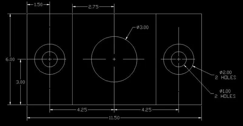
step-7: Specify the size of rectangle of 11.5,6
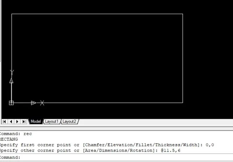
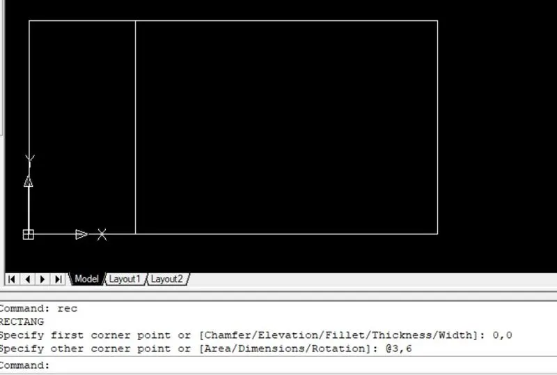
step-8: Type "REC" to plot next elements of 3,6
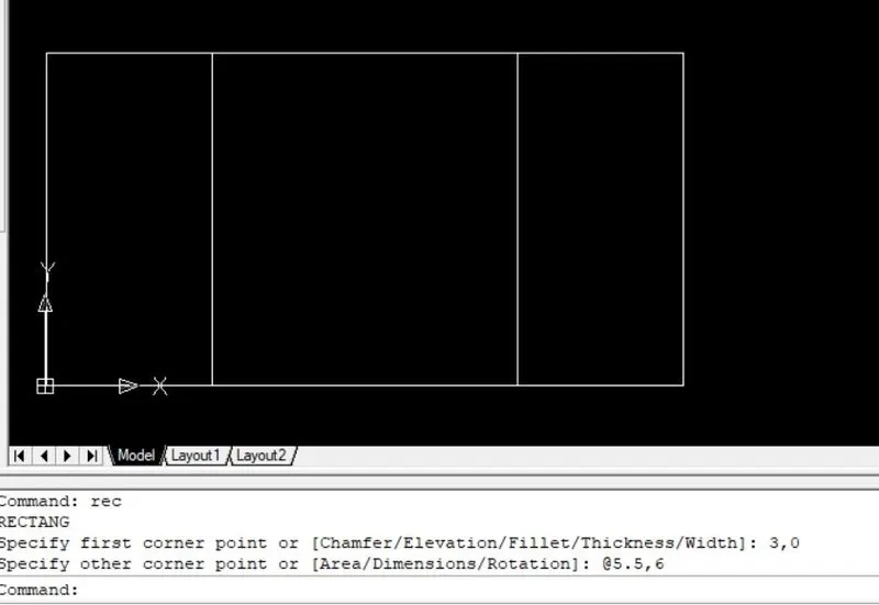
step-9: Type "REC" to plot next element of 5.5,6.
step-10: Type "C" to envoke circlle tool
step-11: Create circle at centre of 1.5,3
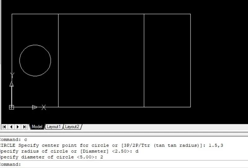
step-12: Select diameter of 1 and same coordinate with the dia of 2.
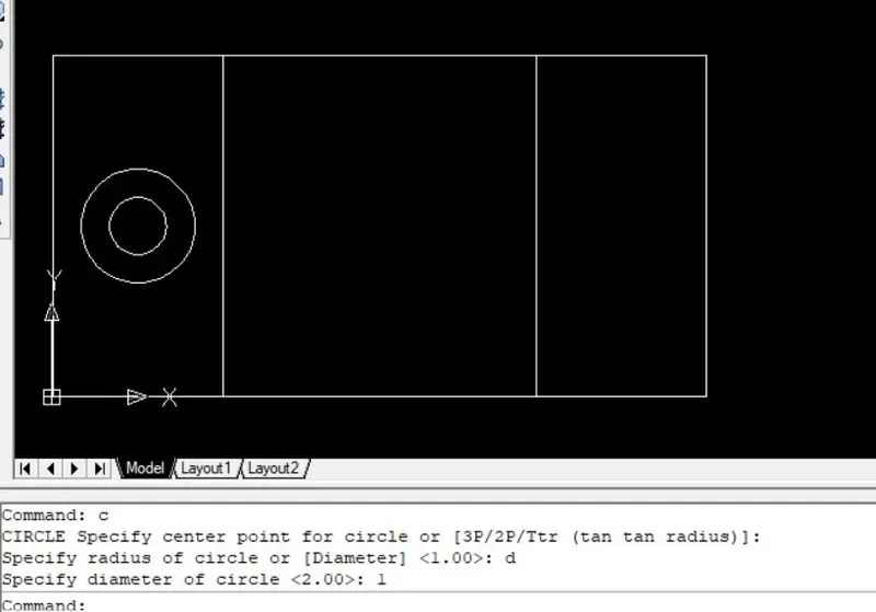
step-13: Type "CO" copy that two circle's with reference of left top of rectangle
step-14: Plot adjacent side of requied place.
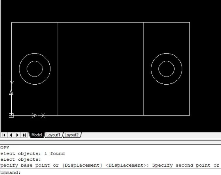
step-15: Type "C" circle to plot initial coordinate of 5.75,3
step-16: Select diameter of 3.
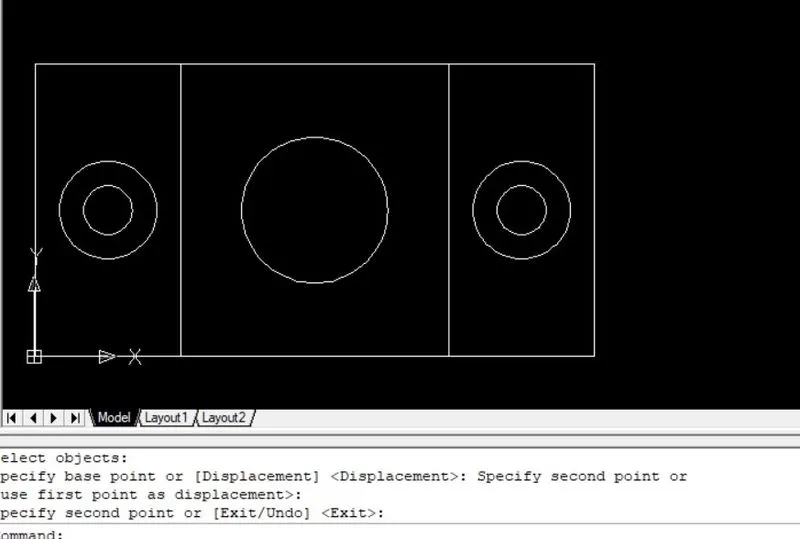
step-17: Type "DIMLIN" to mark all the dimensions for reference.
step-18: Close the tool.
RESULT:
- Here is the final output of given geometry by using AutoCAD.
6. Drawing-6:
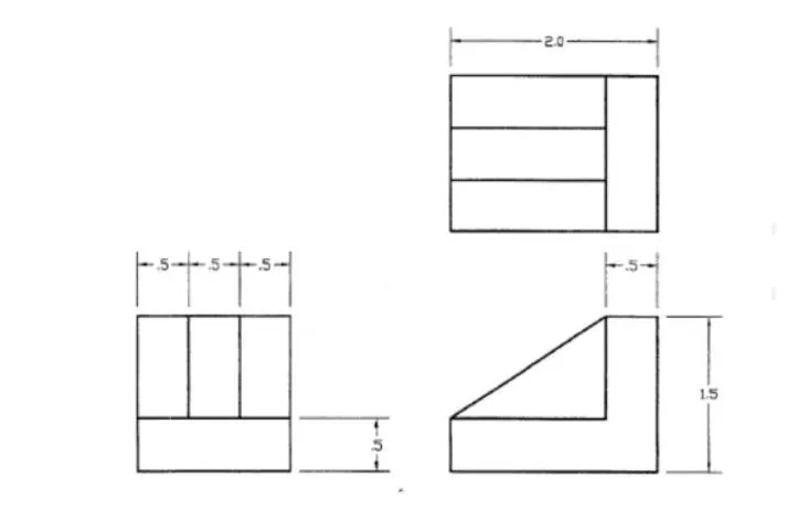
AIM: To draft given geometry using decimal units.
INTRODUCTION:
Line: Specify the starting point of the line by clicking mouse then will be prompted to specify the second point. It can be used for making simple lines in the drawing.
Dimlinear: To measure linear dimensions of all drawing elements.
Text: Single line text and multi line text helps to write notes in the drawing for future reference.
PROCEDURE:
step-1: Go to Open new drawing sheet.
step-2: Type "UN" command to open a dialogue box of units. Over there we change units into "Decimal" and select the precision we required, here i select '0.0'.
step-3: Type "LIMITS" command to set a limit of drawing sheet. when you enter limits, the command line asking left lower corner of the sheet, put 0,0 and press enter. Now command line asking right upper corner of sheet, we just put 100,100. We can choose maximum value which we needed to plot the diagram.
step-4: Than click enter to close the command.
step-5: Type "L" Line tool to specify initial point of 0,0
step-6: Specify next point of 1.5 towards +ve X-direction
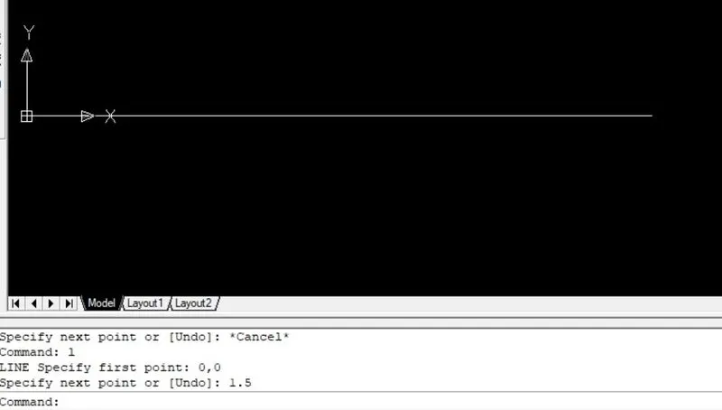
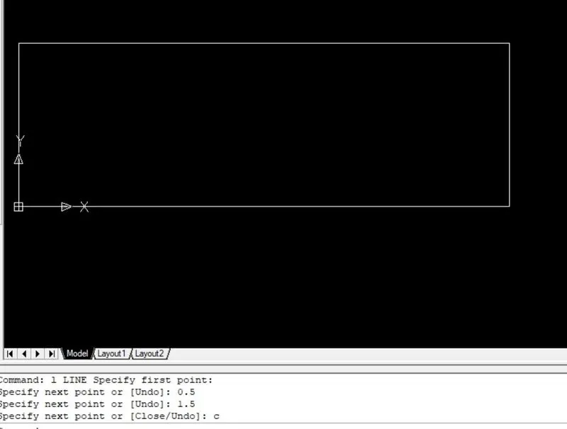
step-7: specify next point of 0.5 towards +ve Y-direction
step-8: specify next point of 1.5 towards -ve X-direction
step-9: Type C to close the line tool.
step-10: Type "L" line tool to select 0,0.5
step-11: Specify next point of 1 towards +ve Y-direction
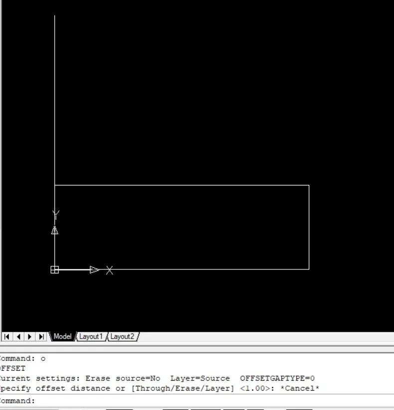
step-12: Now type "OFFSET" command and give offset distance of 0.5
step-13: Do offset howmany times we required.
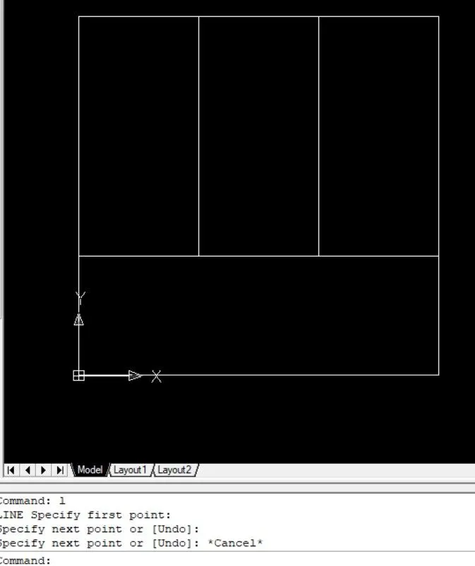
step-14: Type "L" to mark specify distance from previous drawing
step-15: Specify next point of 2.0 towards +ve X-direction
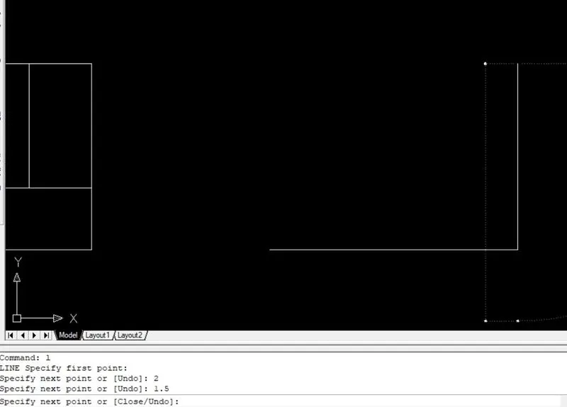
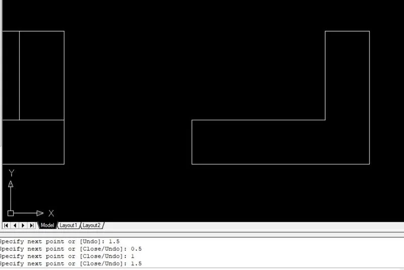
step-16: Specify next point of 1.5 towards +ve Y-direction
step-17: specify next point of 0.5 towards -ve X-direction
step-18: specify next point of 1 towards -ve Y-direction
step-19: specify next point of 1.5 towards -ve X-direction
step-20: Type close to where we start.
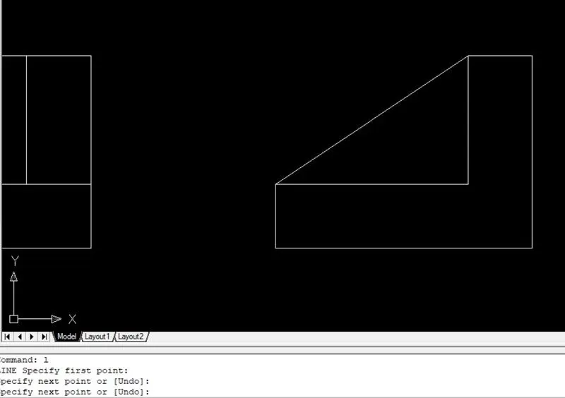
step-21: Type "L" to draw diagonal line to select first and end point.
step-22: Type "L " to draw section of reference drawing.
step-23: Specify next point of 1.5 towards +ve Y-direction
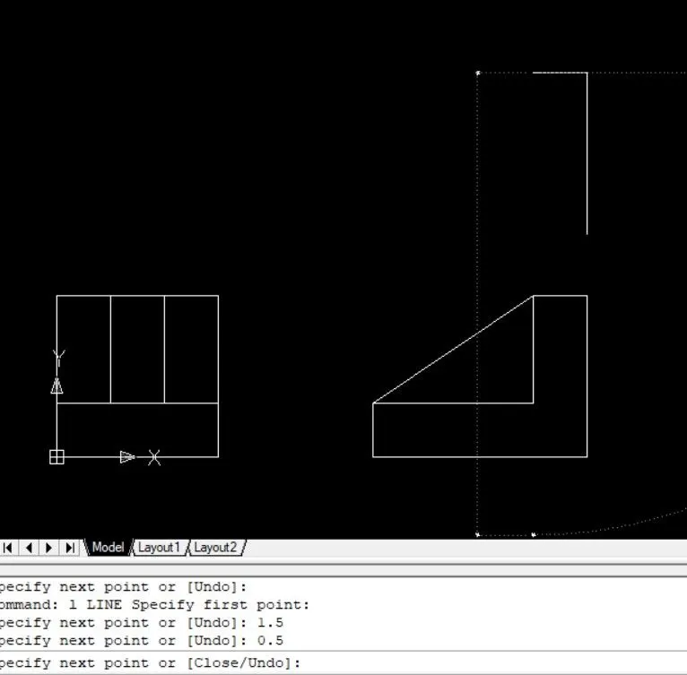
step-24: Specify next point of 0.5 towards -ve X-direction
step-25: specify next point of 1.5 towards -ve Y-direction
step-26: Type C to close the line tool.
step-27: Type "L" line tool to select which point we end
step-28: Specify next point of 1.5 towards -ve X-direction
step-29: Now type "OFFSET" command and give offset distance of 0.5
step-30: Do offset howmany times we required.
step-31: Type "L" to select start and end point to finish the drawing.
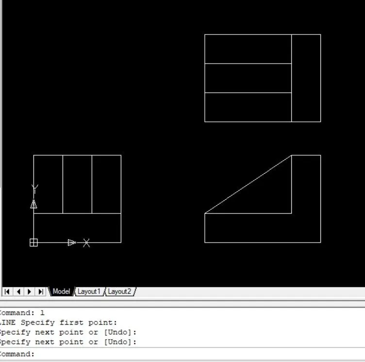
step-31: Type "DIMLIN" to mark all the dimensions.
RESULT:
- Here is the final output of given geometry by using AutoCAD.
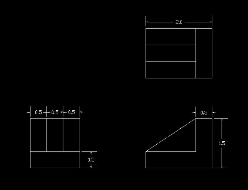
7. Drawing-7:
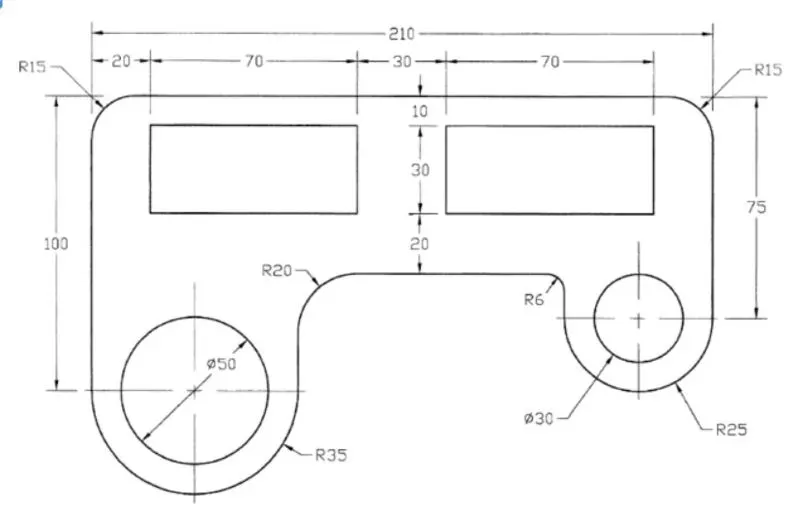
AIM: To draft given geometry using decimal units.
INTRODUCTION:
Line: Specify the starting point of the line by clicking mouse then will be prompted to specify the second point. It can be used for making simple lines in the drawing.
Circle: It is the command used for making a circle in the drawing sheet. By entering "C" to envoke this tool.
ARC: It is used to draw arc in drawing sheet. with the helps of radius and direction and angle.
Dimlinear: To measure linear dimensions of all drawing elements.
Dimaligned: It helps to measure aligned elements. "DIMALI" helps to envoke the tool.
Dimdiameter: It is used to measure diameter of circle.
Dimangular: It is used to measure angle of two elements
Text: Single line text and multi line text helps to write notes in the drawing for future reference.
PROCEDURE:
step-1: Go to Open new drawing sheet.
step-2: Type "UN" command to open a dialogue box of units. Over there we change units into "Decimal" and select the precision we required, here i select '0.0'.
step-3: Type "LIMITS" command to set a limit of drawing sheet. when you enter limits, the command line asking left lower corner of the sheet, put 0,0 and press enter. Now command line asking right upper corner of sheet, we just put 100,100. We can choose maximum value which we needed to plot the diagram.
step-4: Than click enter to close the command.
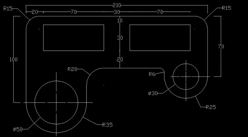
step-5: Type "L" Line tool to point in the sheet.
step-6: Specify next point 35 towards -ve X-direction
step-7: Specify next point 100 towards +ve Y-direction
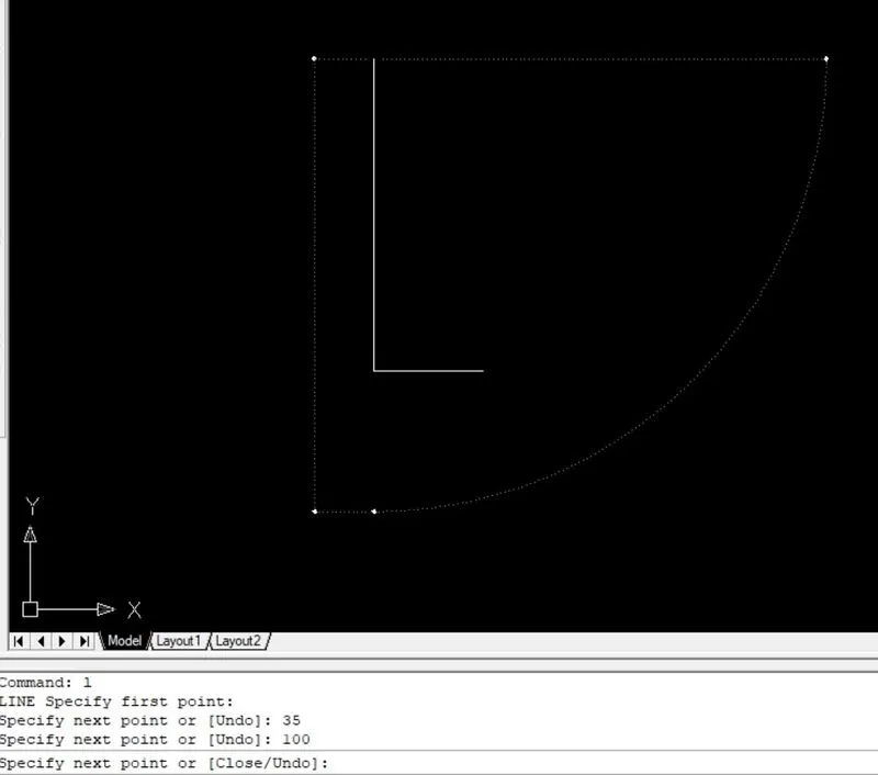
step-8: Specify next point 210 towards +ve X-direction
step-9: Specify next point 70 towards -ve Y-direction
step-10: Specify next point 25 towards -ve X-direction
step-11: Press enter to close the tool.
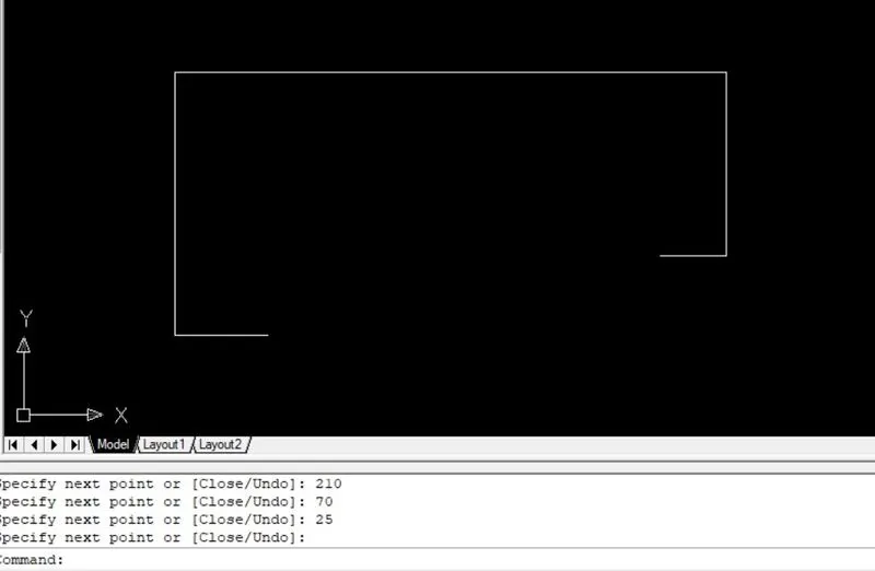
step-12: Type "ARC" click initial point
step-13: Select Center click center point and start point of radius and select end point.
step-14: Press enter to close the tool.
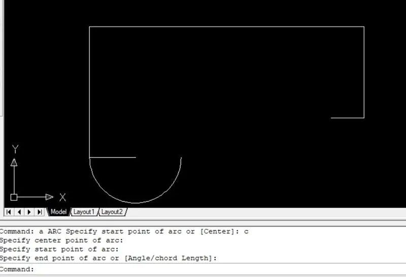
step-15: Type "ARC" click initial point
step-16: Select Center click center point and start point of radius and select end point.
step-17: Press enter to close the tool.
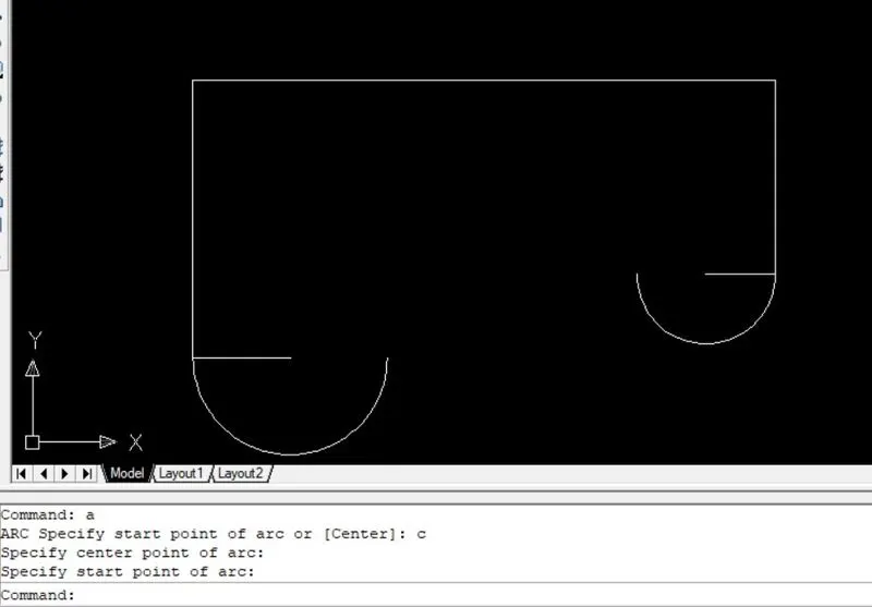
step-18: Type "OFFSET" tool with a distance of 60 from top line.
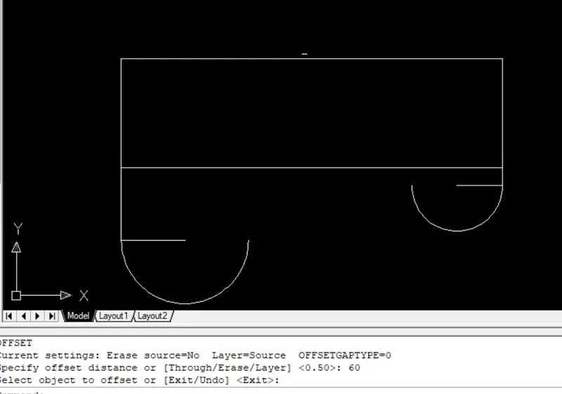
step-19: Type "L" of two edges from ARC end point.
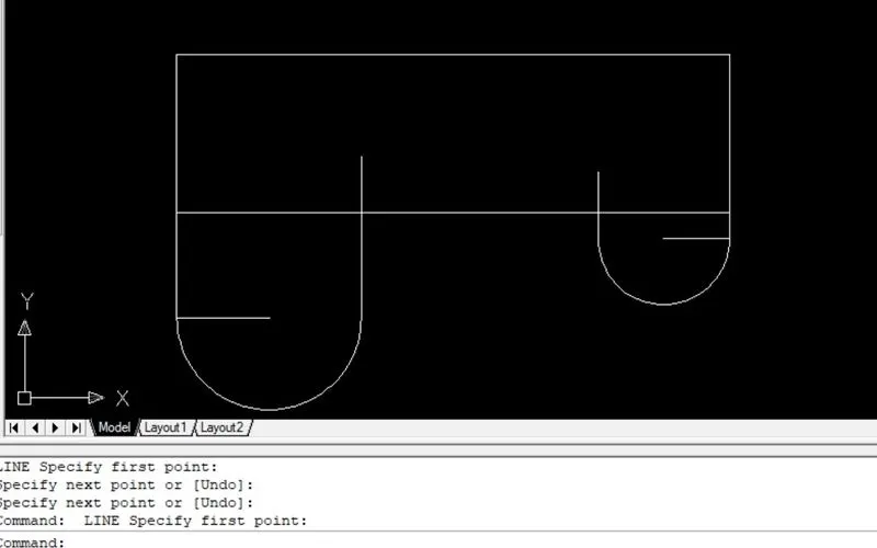
step-29: Type "TRIM" of trim extended part of elements that doesn't required for drawing.
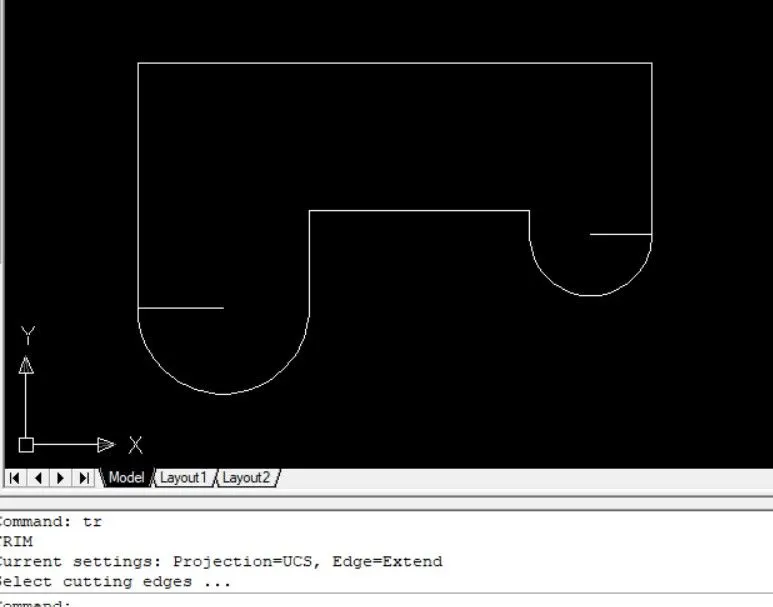
step-30: Type "C" circle select center point
step-31: Give input diameter of 50
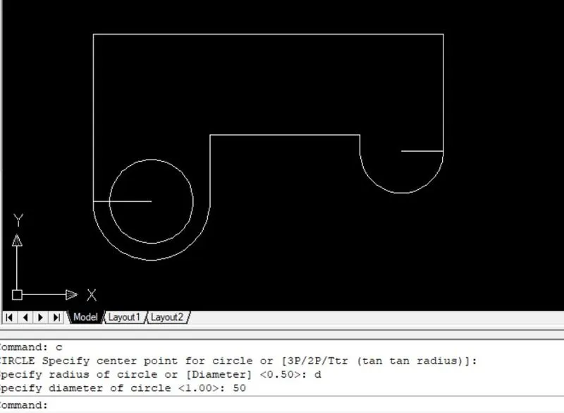
step-32: Type "C" circle select center point
step-33: Give input diameter of 30
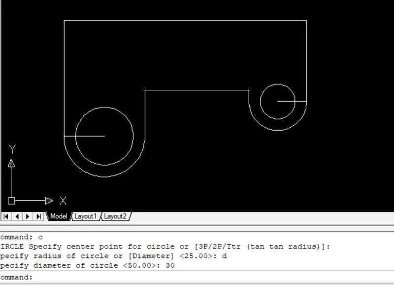
step-34: Type "FILLET" to fillet the all edges.
step-35: Select Radius 15 and select both the edges.
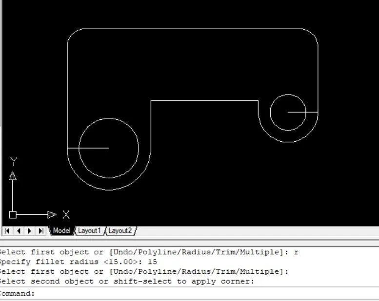
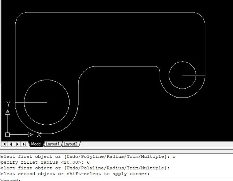
step-36: Repeat Fillet with the radius of 20 by selection of two lines
step-37: Repeat FILLET with the radius 15 by selection of two lines
step-38: Repeat FILLET with the radius 6 by selection of two lines
step-39: Type "OFFSET" to 10 from top and 20 from side.
step-40: Type "OFFSET" to 70 from side and 30 from top to finish one rectangle.
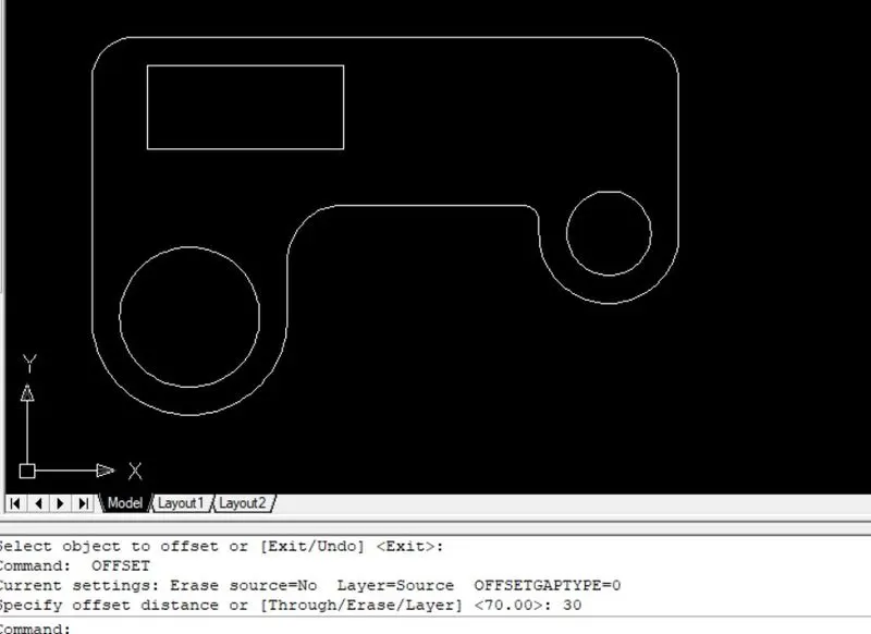
step-41: Type "FILLET" with zero radius to join rectangular corner.
step-42: Type "CO" to copy rectangle with a distance of 100 from starting point.
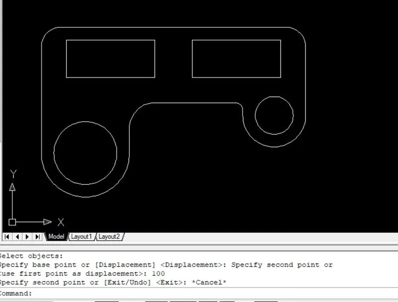
step-39: Type "DIMLIN" to mark all the linear dimensions
step-40: Type "DIMDIA" to mark diameter of the circle.
step-41: Type "DIMRAD" to mark radius of the arc.
RESULT:
- Here is the final output of given geometry by using AutoCAD.
8. Drawing-8:
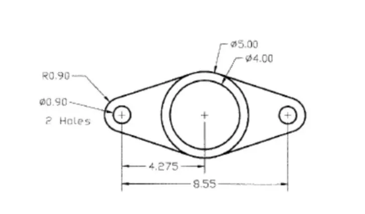
AIM: To draft given geometry using decimal units.
INTRODUCTION:
Line: Specify the starting point of the line by clicking mouse then will be prompted to specify the second point. It can be used for making simple lines in the drawing.
Circle: It is the command used for making a circle in the drawing sheet. By entering "C" to envoke this tool.
ARC: It is used to draw arc in drawing sheet. with the helps of radius and direction and angle.
Dimlinear: To measure linear dimensions of all drawing elements.
Dimdiameter: It is used to measure diameter of circle.
PROCEDURE:
step-1: Go to Open new drawing sheet.
step-2: Type "UN" command to open a dialogue box of units. Over there we change units into "Decimal" and select the precision we required, here i select '0.0'.
step-3: Type "LIMITS" command to set a limit of drawing sheet. when you enter limits, the command line asking left lower corner of the sheet, put 0,0 and press enter. Now command line asking right upper corner of sheet, we just put 100,100. We can choose maximum value which we needed to plot the diagram.
step-4: Than click enter to close the command.
step-5: Type "L" Line tool to point in the sheet.
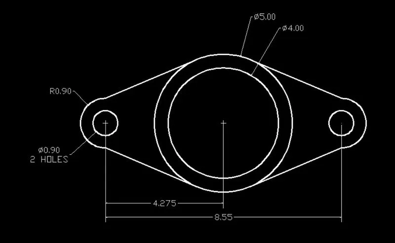
step-6: Specify next point of 8.55 towards +ve X-direction
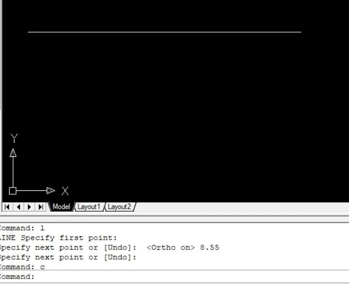
step-7: Type "C" circle select center point
step-8: Select Diameter of 0.9
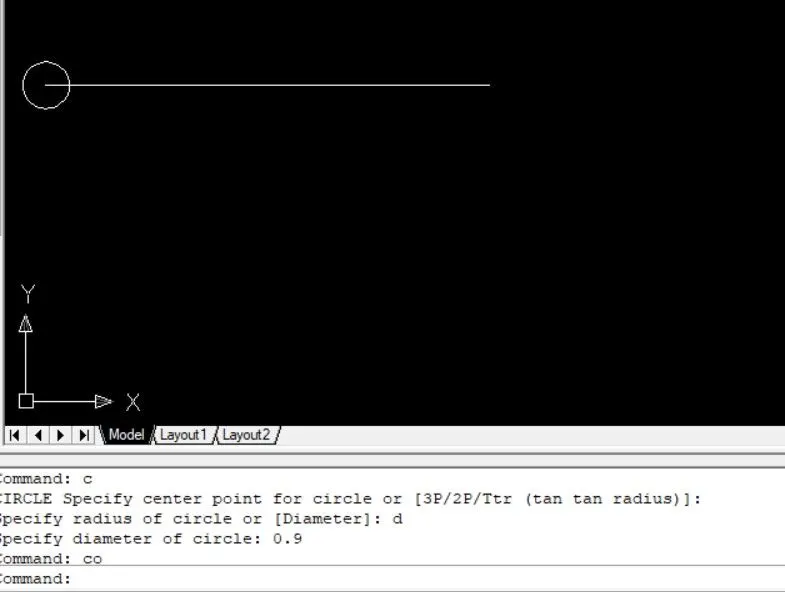
step-9: Type "CO" copy that circle with respect to center point to locate other side.
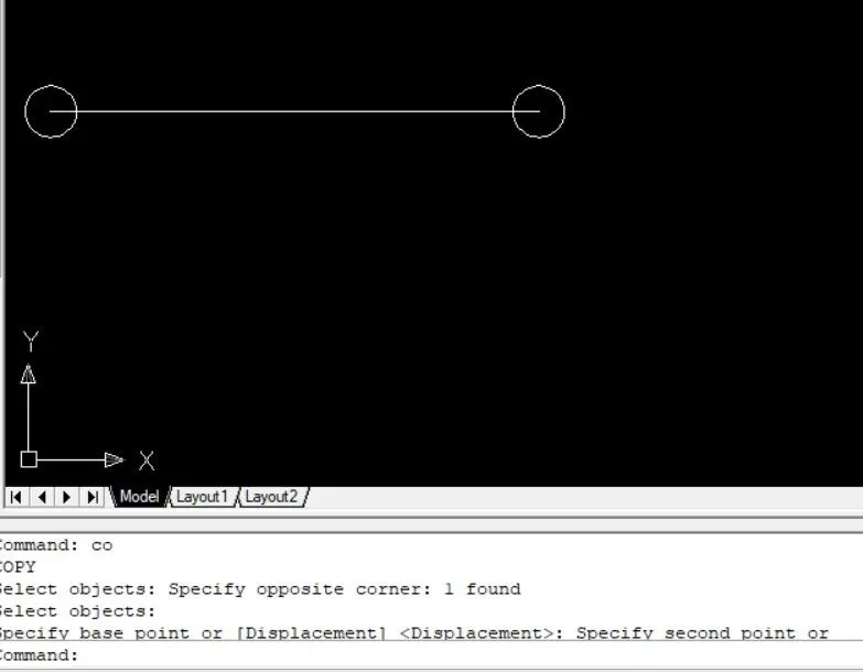
step-10: Type "C" circle to track and select center point of the line.
step-11: Select diameter of 4 and 5 to draw two circles.
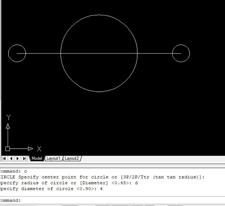
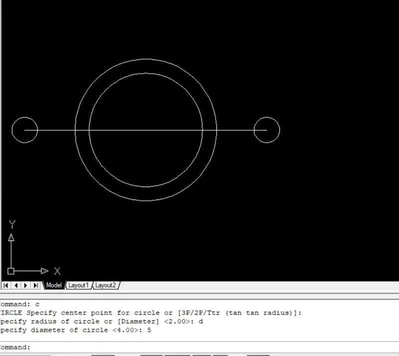
step-12: Type "ARC" to select edge of line.
step-13: Select center and with a radius of 0.9 and locate start and end point.
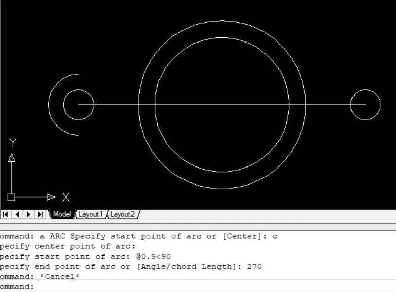
step-14: Type "MI" mirror that arc with reference to edge of the line and place it to other side.
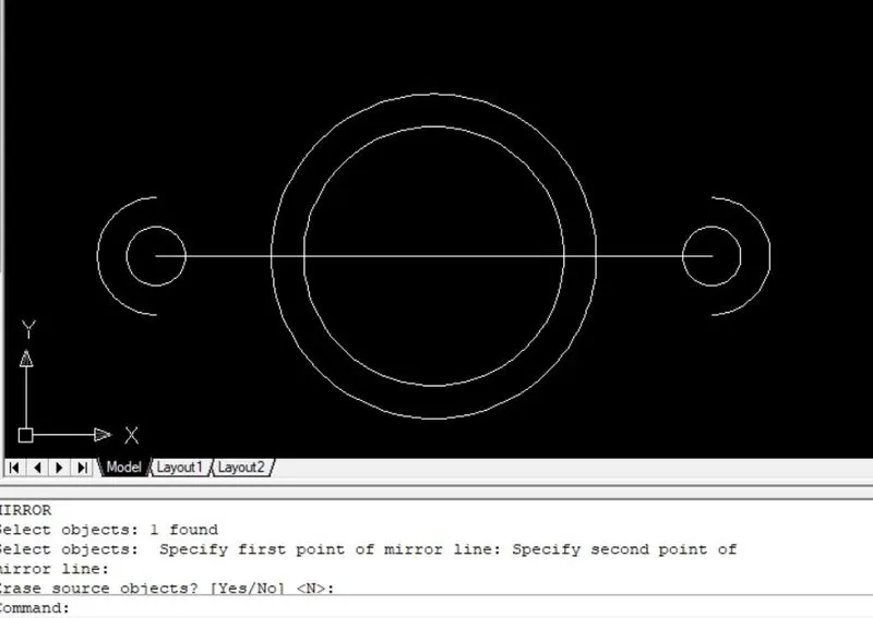
step-15: Type "L" line tool to select one edge of arc to the outer circle tangent edge.
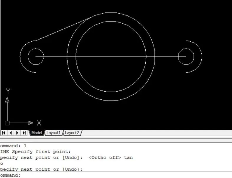
stpe-16: Type "MIRROR" to select that line and mirrored the object.
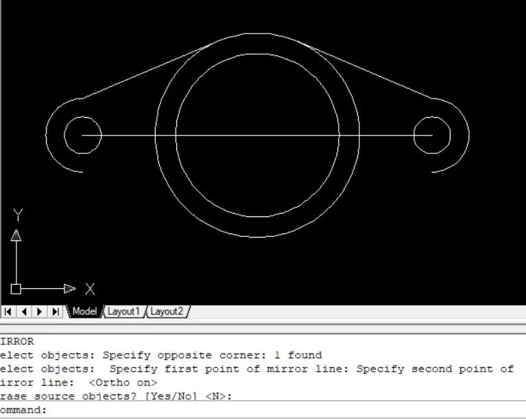
step-17: Type "MIRROR" now select two lines and mirrored both lines with respect to center.
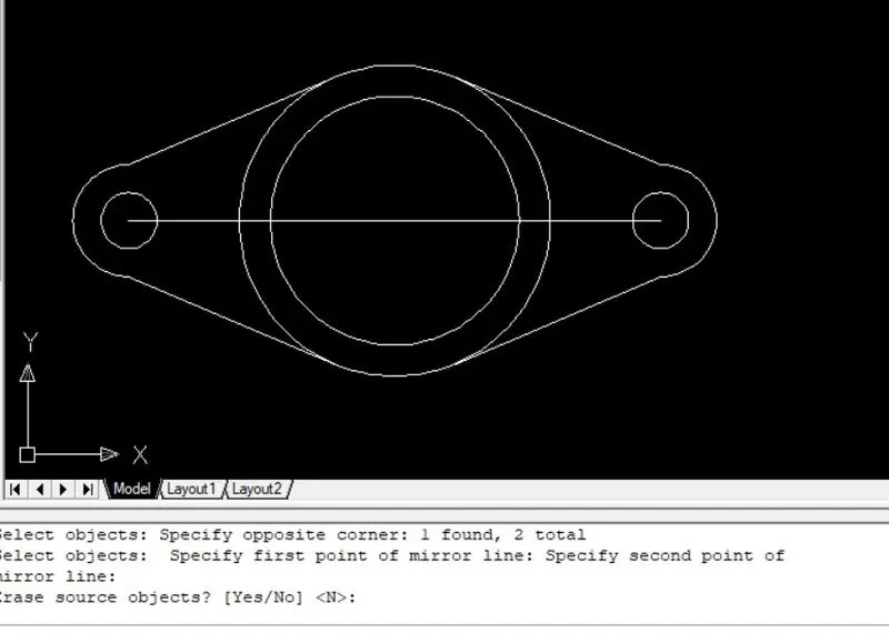
step-18: Type "ERASE" to erase the initial line of 8.55 distance.
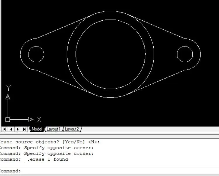
step-19: Type "DIMLIN" to mark the linear dimensions
step-20: Type "DIMDIA" to mark tha diameter of circle.
step-21: Type "DIMRAD" to mark the radius of the arc.
step-22: Type "ED" to edit dimension text to mention "2 Holes".
RESULT:
- Here is the final output of given geometry by using AutoCAD.
9. Drawing-9:
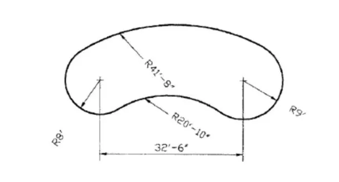
AIM: To draft given geometry using Engineering units.
INTRODUCTION:
ARC: It is used to draw arc in drawing sheet. with the helps of radius and direction and angle.
Dimlinear: To measure linear dimensions of all drawing elements.
PROCEDURE:
step-1: Go to Open new drawing sheet.
step-2: Type "UN" command to open a dialogue box of units. Over there we change units into "Architectural" and select the precision we required, here i select 0'0".
step-3: Type "LIMITS" command to set a limit of drawing sheet. when you enter limits, the command line asking left lower corner of the sheet, put 0,0 and press enter. Now command line asking right upper corner of sheet, we just put 100',100'. We can choose maximum value which we needed to plot the diagram.
step-4: Than click enter to close the command.
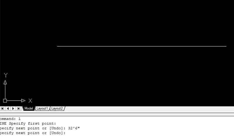
step-5: Type "L" Line tool to point in the sheet.
step-6: Specify next point of 32'6".
step-7: Type "ARC" to select edge of the line.
step-8: Select center and @8<135
step-9: End @315 degree.
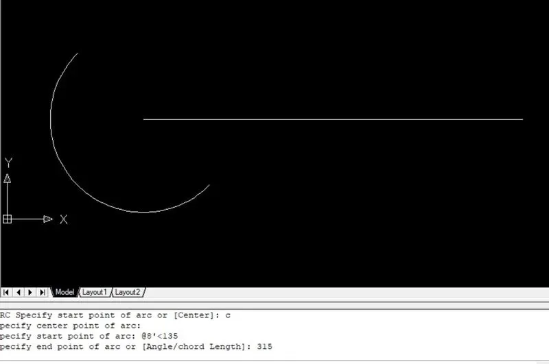
step-10: Type "ARC" to select edge of the line
step-11: Select center and @9<45
step-12: End @225 degree.
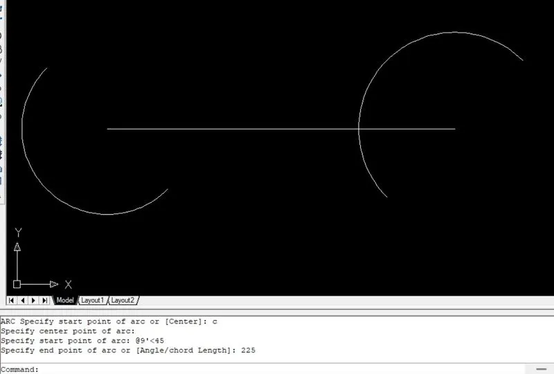
step-13: Type "MIRROR" to mirror the arc with respect to center and radius.
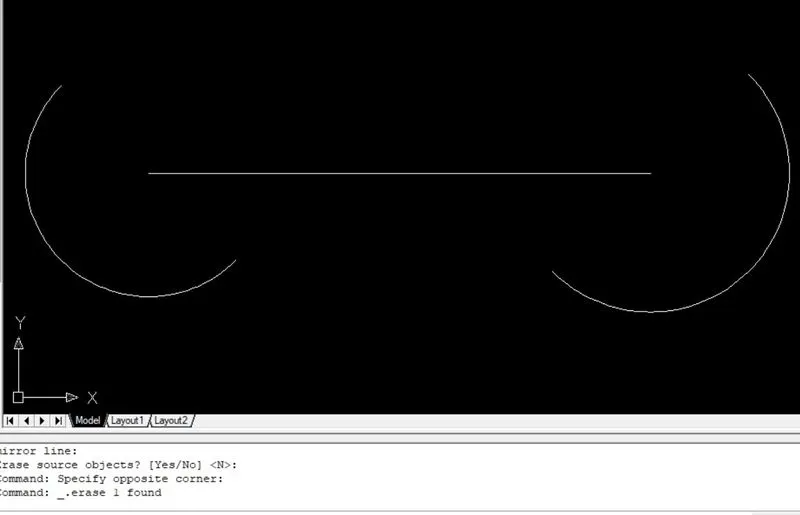
step-14: Type "ARC" to click one edge of arc
step-15: select End to click end of other side.
step-16: Enter input of arc radius 20'10" and give direction from cursor.
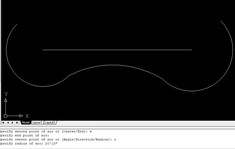
step-17: Type "ARC" to click one edge of arc
step-18: select End to click end of other side.
step-19: Enter input of arc radius 41'8" and give direction from cursor.
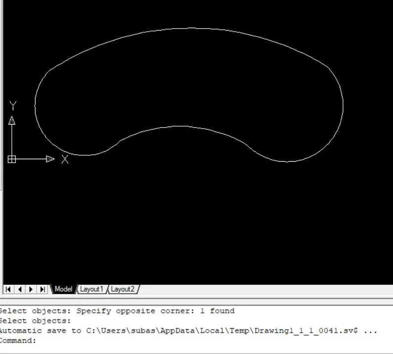
step-20: Type "DIMRAD" to mark all the radius of ARC
step-21: Type "DIMLIN" to mark the linear directions.
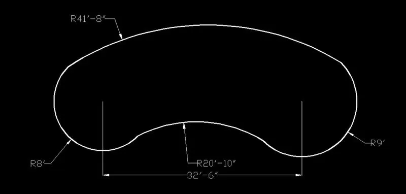
RESULT:
- Here is the final output of given geometry by using AutoCAD.
10. Drawing-10:
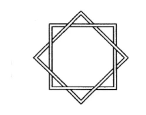
AIM: To draft given geometry using Engineeringunits.
INTRODUCTION:
Polygon: This tool helps to draw multiple sides of elements by entering "POLYGON" command.
Trim: It is one kind of a modification tool to trim extended edges from elements.
PROCEDURE:
step-1: Go to Open new drawing sheet.
step-2: Type "UN" command to open a dialogue box of units. Over there we change units into "Architectural" and select the precision we required, here i select 0'0".
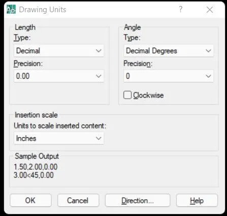
step-3: Type "LIMITS" command to set a limit of drawing sheet. when you enter limits, the command line asking left lower corner of the sheet, put 0,0 and press enter. Now command line asking right upper corner of sheet, we just put 100',100'. We can choose maximum value which we needed to plot the diagram.
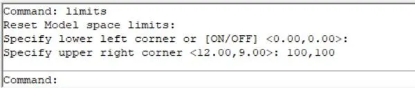
step-4: Than click enter to close the command.
step-5: Type "POLYGON" to enter four sides
step-6: Select Inscribed in circle
step-7: Select radius of 10<270
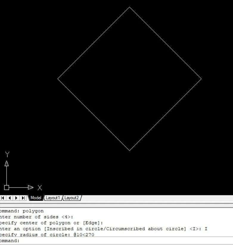
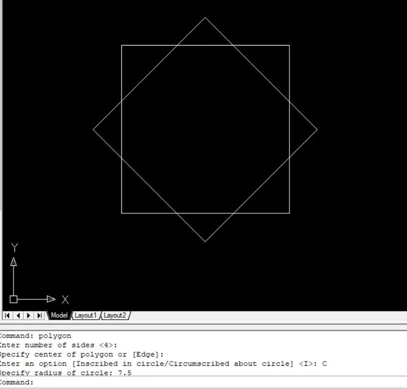
step-8: Type "POLYGON" to enter four sides
step-9: Select Circumscribed circle
step-10: Select radius of 7.5
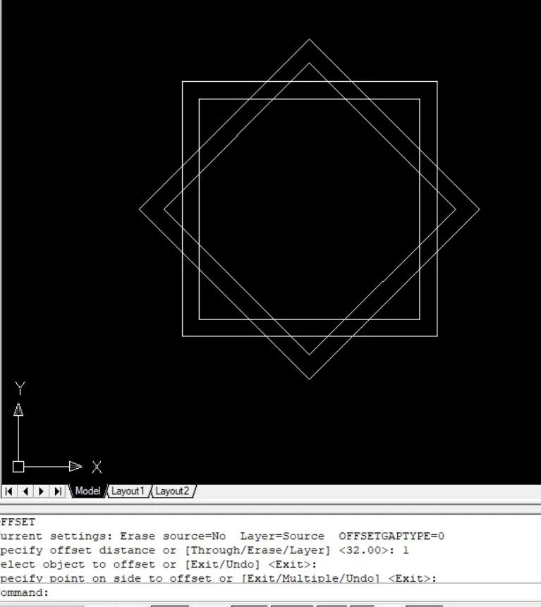
step-11: Type "OFFSET" with distance of 1 to offset both rectangles
step-12: Type "TRIM" to trim according to give geometry.
step-13: Change line weight to 0.3 and "LW" to select display of line weight.

RESULT:
- Here is the final output of given geometry by using AutoCAD.
11. Drawing-11:
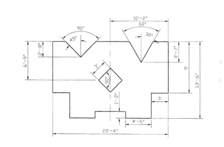
AIM: To draft given geometry using Engineeringunits.
INTRODUCTION:
Line: Specify the starting point of the line by clicking mouse then will be prompted to specify the second point. It can be used for making simple lines in the drawing.
Dimlinear: To measure linear dimensions of all drawing elements.
Dimaligned: It helps to measure aligned elements. "DIMALI" helps to envoke the tool.
Dimdiameter: It is used to measure diameter of circle.
Dimangular: It is used to measure angle of two elements
Text: Single line text and multi line text helps to write notes in the drawing for future reference.
PROCEDURE:
step-1: Go to Open new drawing sheet.
step-2: Type "UN" command to open a dialogue box of units. Over there we change units into "Architectural" and select the precision we required, here i select 0'0".
step-3: Type "LIMITS" command to set a limit of drawing sheet. when you enter limits, the command line asking left lower corner of the sheet, put 0,0 and press enter. Now command line asking right upper corner of sheet, we just put 100',100'. We can choose maximum value which we needed to plot the diagram.
step-4: Than click enter to close the command.
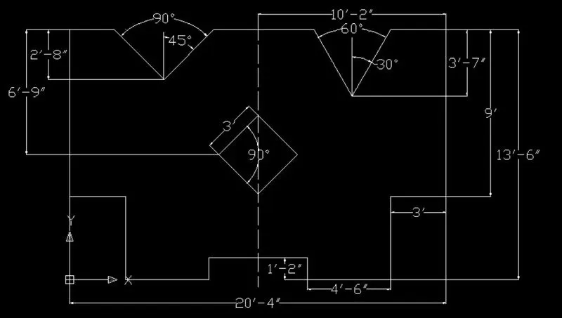
step-5: Type "L" command mention initial coordinate of 10'2",13'6"
step-6: Specify next point of 10'2" towards +ve X-direction
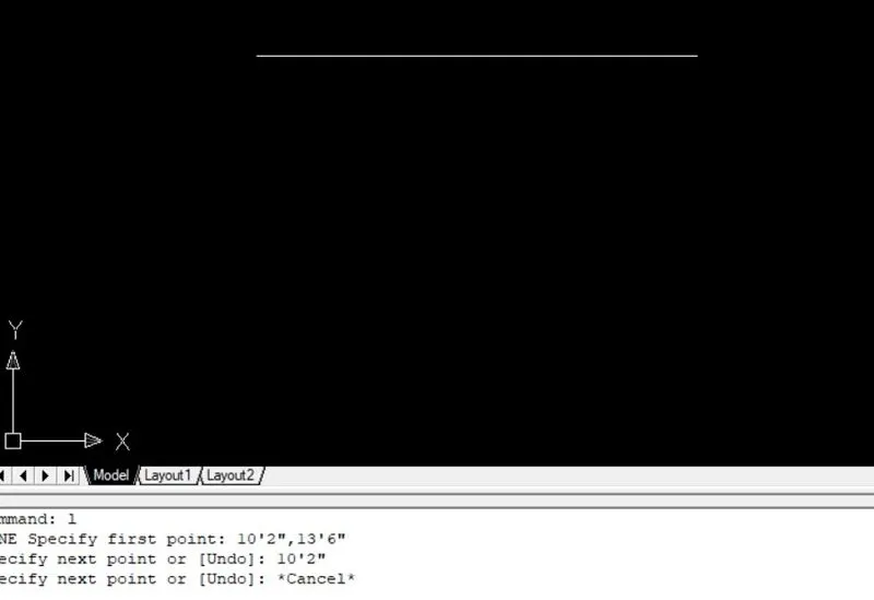
step-7: Specify next point of 9'0" towards -ve Y-direction
step-8: Specify next point of 3'0" towards -ve X-direction
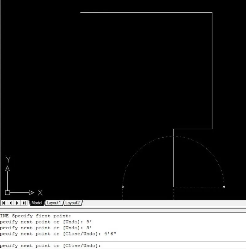
step-9: Specify next point of 4'6" towards -ve Y-direction
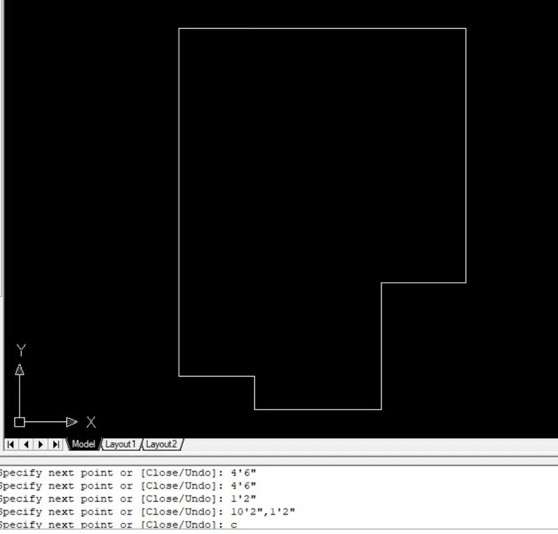
step-10: Specify next point of 4'6" towards -ve X-directoin
step-11: Specify next point of 1'2" towards +ve Y-direction
step-12: Specify next point of 10'2",1'2"
step-13: Type "c" to close the line tool where we initiate the drawing.
step-14: Type "POLYGON" tool to select 4 side and give center point of 10'2",6'9"
step-15: Select Incribed circle of radius @2'1.5" < 90
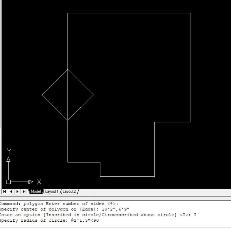
step-16: Type "OFFSET" to 3'7" and offset of 5'1" from center line.
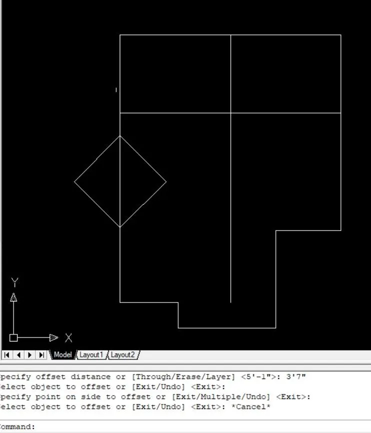
step-17: Type "L" to @5'<60, extended length have to be trimmed by using "TR" command.
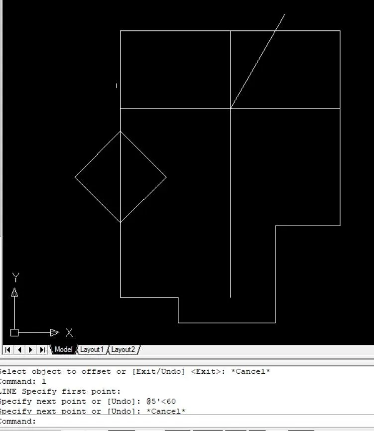
step-18: Type "MI" to mirror particular line to make triangle.
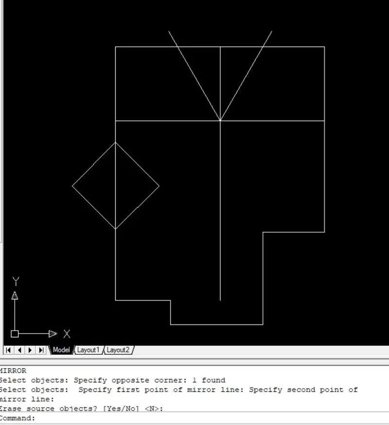
step-19: Type "MI" to mirror by selecting center line.
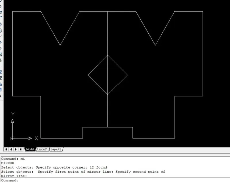
step-20: Type "ERASE" to erase triangle part.
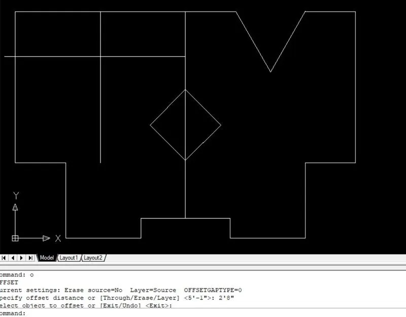
step-21: Type "OFFSET" to 2'8" and offset of 5'1" from center line.
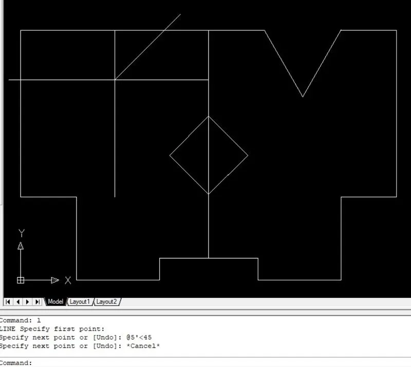
step-22: Type "L" to @5'<45, extended length have to be trimmed by using "TR" command.
step-23: Type "MI" to mirror particular line to make triangle.
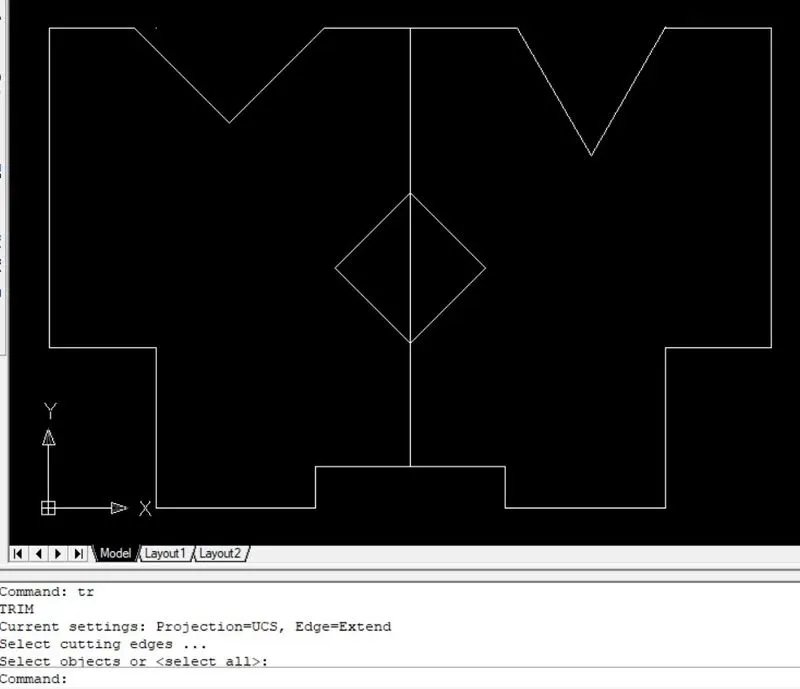
step-24: Type "DIMLIN" to measure all the dimensions
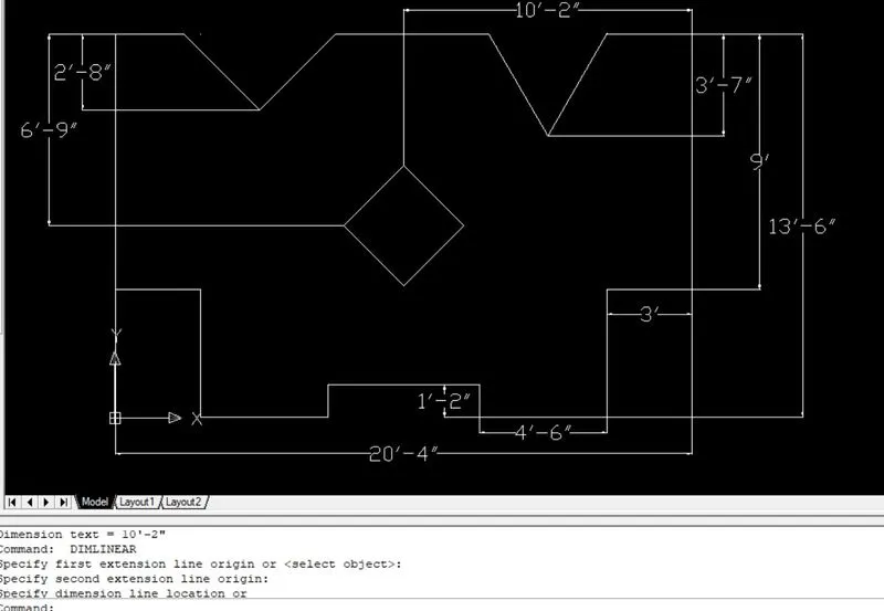
step-25: Type "DIMANG" to mark all the angles.
RESULT:
- Here is the final output of given geometry by using AutoCAD.