Creating a Floor plan, Footing detail and Isometric view using AutoCad
Aim:
To create a floor plan, footing detail and isometric view by using AutoCAD.
Introduction:
AutoCAD has so many tools that can used to build structural drawings and 3D models. Here, we used AutoCAD to draw floor plan, footing detail drawing and isometric view.
1.LINE:
We can invoke the Line tool by pressing "L" in the command box and will have to specify starting point of the object we are used to draw. And mention the next remaining points to draw the diagram. Finally, closing the tool by pressing enter. This tool used enormous way in plotting structural drawing.
2.POLYLINE:
It means a many line in single entity. To draw a polyline we just invoke the "PL" command in the command box and used to draw the objects. By pressing enter to close the tool. In this way we has single element with multiple lines.
3.RECTANGLE:
We can draw rectangles by using Rectangle command in the command box and we give corners of the objectsto plot rectangle in drawing sheet.
AutoCAD has modification tools alos. It used to modify, move, copy, trim, extend, stretch the existing objects and make things easily.
1.MOVE:
Type "MOVE" in command box to invoke the tool and it used to move existing sketched objects wherever we want to shift and by pressing enter to close the invoking tool.
2.COPY:
Type "COPY" in command box to wake this tool and it is used to copy the sketched objects where we need to draw and it is very helpful when we had to draw same element in different area's. So that we just draw one time and copied that to paste where we need to put.
3.TRIM:
Type "TRIM" to waking up this tool and it is used to cut the extended portion of drawing which sketched beyond the limit of actual dimensions.
4.EXTEND:
It is exactly opposite to Trim tool. We can use this to extend the drawings and some places we need to complete unfinished edges.
5.OFFSET:
This tool is helps to draw parallel lines, polylines, circle, etc., while we use this tool we enter the specific distance to offset the objects.
6.ARRAY:
In some cases, we need to draw same objects in multiples times and specific distance. So that, we use this tool to draw by mention the required distance and number of rows and columns we need.
7.FILLET:
The edges in a model are generally filleted to reduce the area of stress concentration. The fillet tool helps form round corners between any two entities that form a sharp vertex.
C.S. OF LOAD BEARING WALL OVER SPREAD FOOTING:
- Initially, we need to workout the given drawing and to think which tool is opt for draw in a fastest way.
- To select "Polyline" tool to draw the footing.
- Type specify point of 0.9 width of the footing.
- Type next specify point 0.25 depth of the footing.
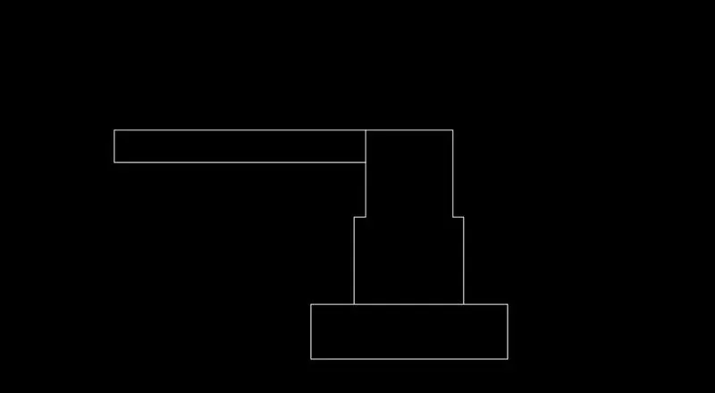
5. In the same way we used to draw the remaining elements in this object.
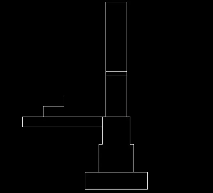
6. Enter the distance of rise and threads of steps to plot. and to give wall thickness for referring the wall in drawing.
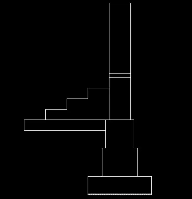
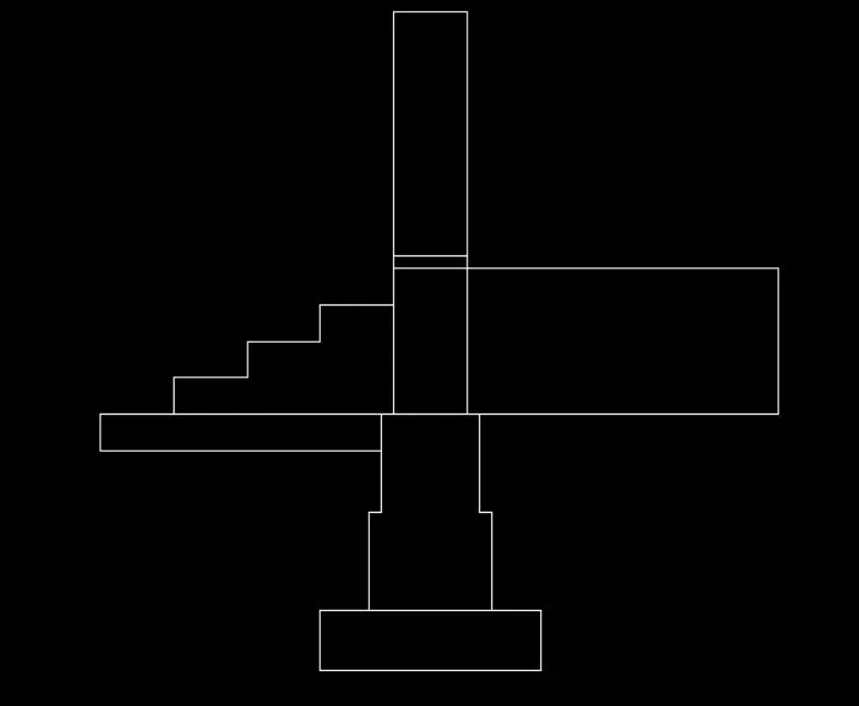
7. Finally, mention all the dimensions of a isolated footing and align a layout to plot the drawing.
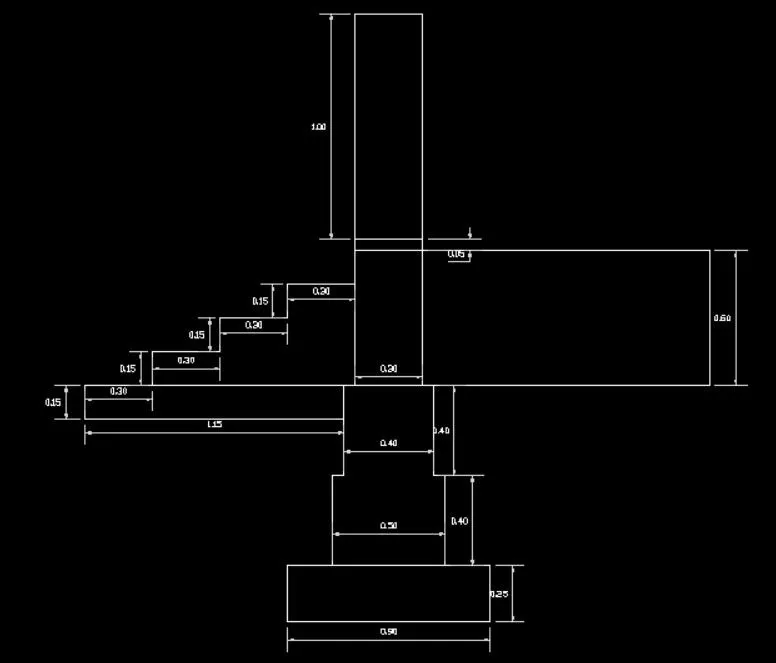
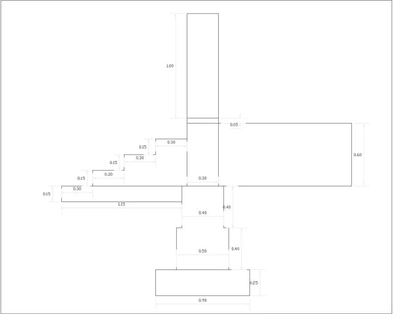
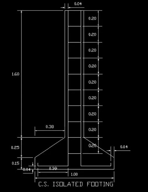
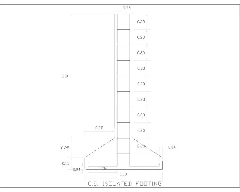
C.S. OF ISOLATED FOOTING:
- Type "L" in command box to invoke the line tool and point somewhere in sheet set to initiate the isolated footing drawing.
- Type the next specify point of 1 to draw footing width.
- Type the next specify point of 0.15 to draw footing depth.
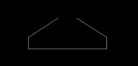
- In the same way footing is completed.
- Next to draw column portion has width of 0.24

- Type "OFFSET" tool to plot reinforcement detail with the distance of 0.04.
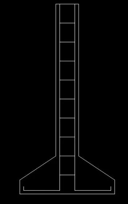
- Finally, mention the all dimensions to plot in layout.
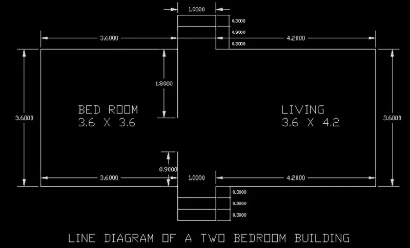
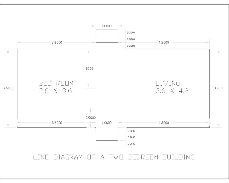
C.S.LINE DIAGRAM OF A TWO BEDROOM BUILDING:
- Type "Polyline" in command box to plot given bedroom building.
- Type next specify point 3.6
- Type next specify point 3.6
- Type next specify point 3.6

- Type next specify point 0.3 to plot entrance of the building.
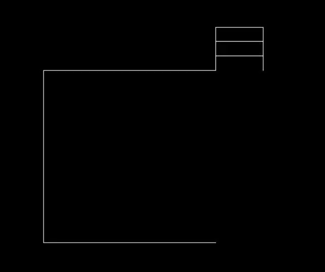
- Meanwhile in the same above way to create sketch for given drawing.
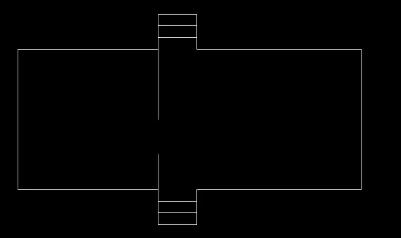
- Finally, mention the all dimensions of diagram and to plot in layout to take print.
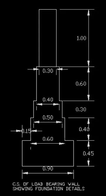
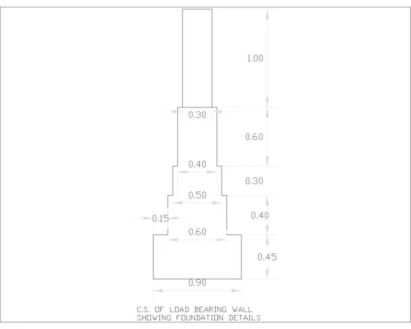
C.S OF LOAD BEARING WALL SHOWING OF FOUNDATION DETAILS:
- Type "L" to invoke line command point specific area in the sheet set.
- Type next specify point 0.9 of width of footing.
- Type next specify point 0.45 of depth of footing
- Type next specify point of 0.15 in the direction of -ve x-axis to plot next level of footing
- Type next specify point of 0.4 in the direction +ve y-axis to plot next step footing depth
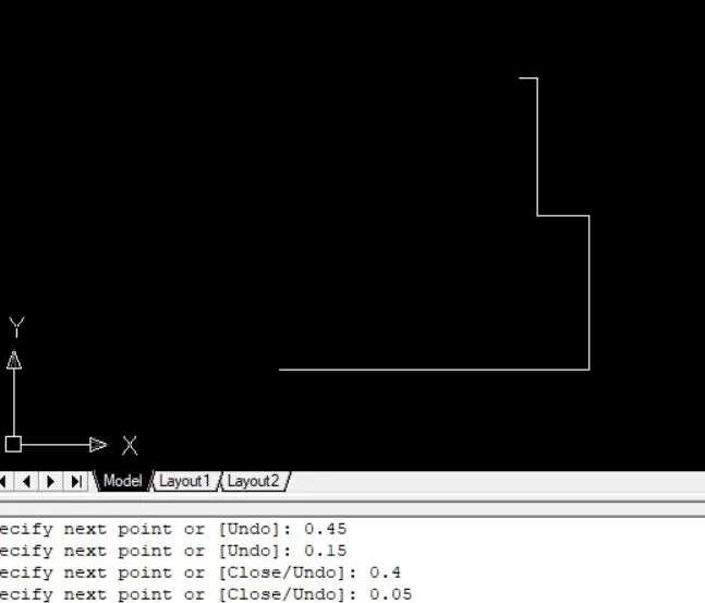
- Type next specify point of 0.05 in the direction -ve x-axis
- Type next specify point of 0.3 in the direction of +ve y-axis
- Type next specify point of 0.05 in the direction of -ve x-axis
- Type next specify point of 0.6 in the direction of +ve y-axis
- Type next specify point of 0.05 in the direction of -ve x-axis
- Type next specify point of 1.00 in the direction of +ve y-axis.
- Type next specify point of 0.3 in the direction of -ve x-axis
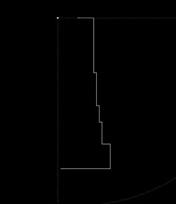
- Type "MI" in the command box to invoke the mirror tool select all elements and use cursor to point a mid level of 0.9 footing.
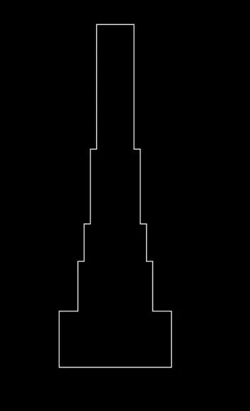
- Change the cursor and plot which direction of mirroring image we need, pressing enter button to close the tool and plot.
- Finally, mention all the dimensions of respective drawing and then plot into layout to take print.
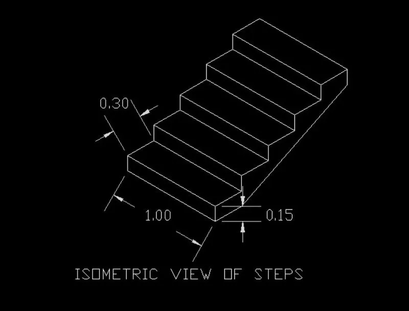
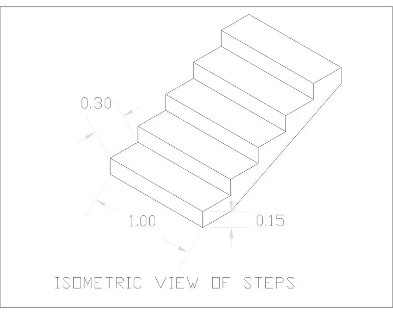
ISOMETRIC VIEW OF STEPS:
- To change Isometric view, Type "DS" in command section > Drafting settings Dialogue box open > Change snap type into Isometric snap.
- Type "L" in command box to invoke line tool and point anywhere in the sheet to initiate the drawing.
- Type next specify point 0.15 is rise of the step.
- Now change Isoplane left and type next specify point 1
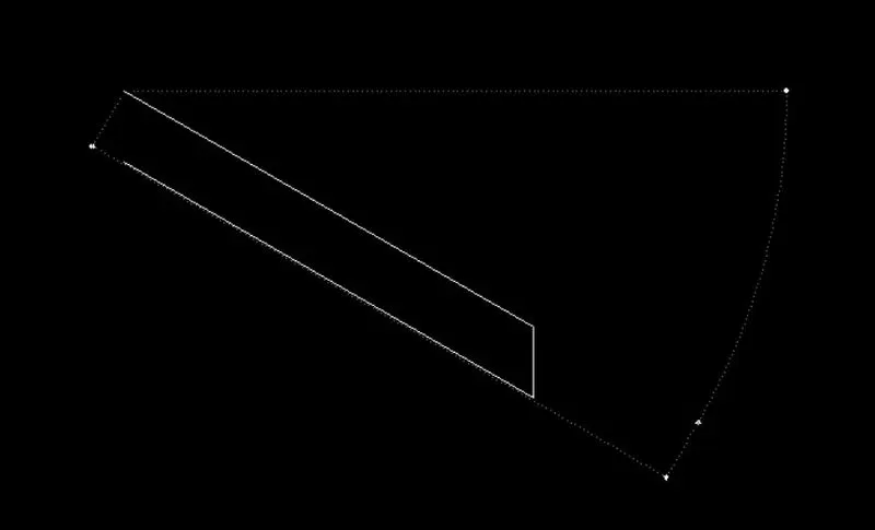
- Type next specify point 0.3
- Type next specify point 1
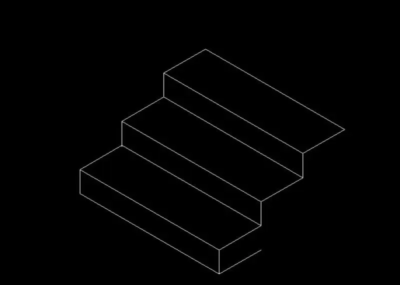
- Type next specify point 0.3 to close the first step.
- Change Isoplane right and type next specify point
- Repeat step 2 to step 8 upto end of steps.
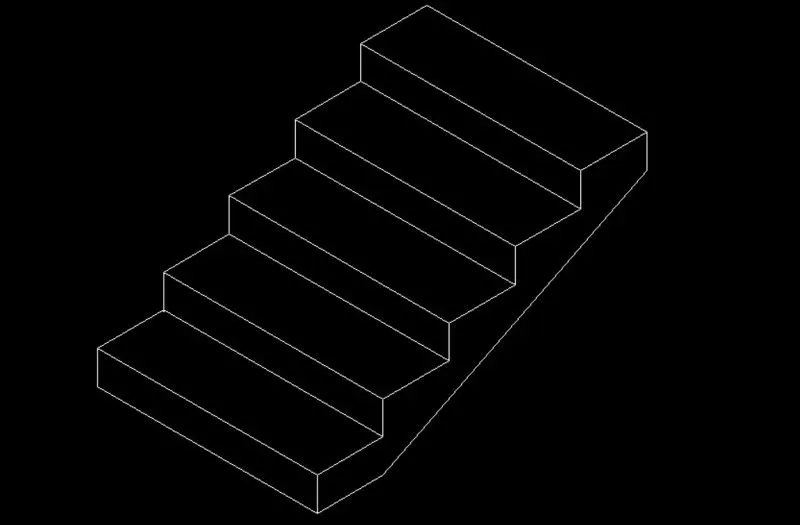
- Type "L" to close the waist slab from bottom to top.
- Finally, mention all the dimensions and then plot to layout to take print.
ISOMETRIC VIEW OF GABLE WALL:
- To change Isometric view, Type "DS" in command section > Drafting settings Dialogue box open > Change snap type into Isometric snap.
- Type "L" in command box to invoke line tool and point anywhere in the sheet to initiate the drawing.
- Type next specify point 1

- Type next specify point 2.42 in the direction of +ve y-axis.
- Type next specify point 1 in the direction +ve x-axis

- Type next specify distance 2.42 in the direction of -ve y-axis
- Type next specify point 1 in the direction of +ve x-axis
- Type next specify point 3 in the direction of +ve y-axis
- Type enter to close the tool
- Type "L" to pen line tool and point initial point and give value of 3 to draw a wall. and press enter to close line tool.
- Type "OFFSET" in command and give distance of 0.3 then select object required to offsetting.

- Type "L" command to draw roof portion of wall. Point cursor at right top of the wall and extend this to 1 point above.
- Type next point towards -ve x-axis plot somewhere to edge of boundary. Now take mid point of door top frame draw line towards +ve Y-axis. now we have intersection of both points. This should be our roof top, now draw other unfinished edges to complete given drawing.
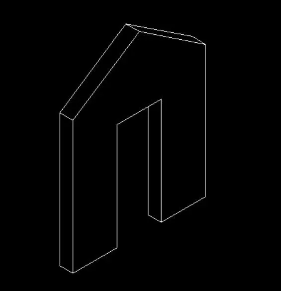
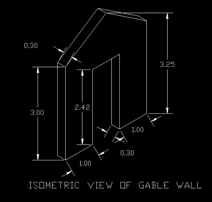
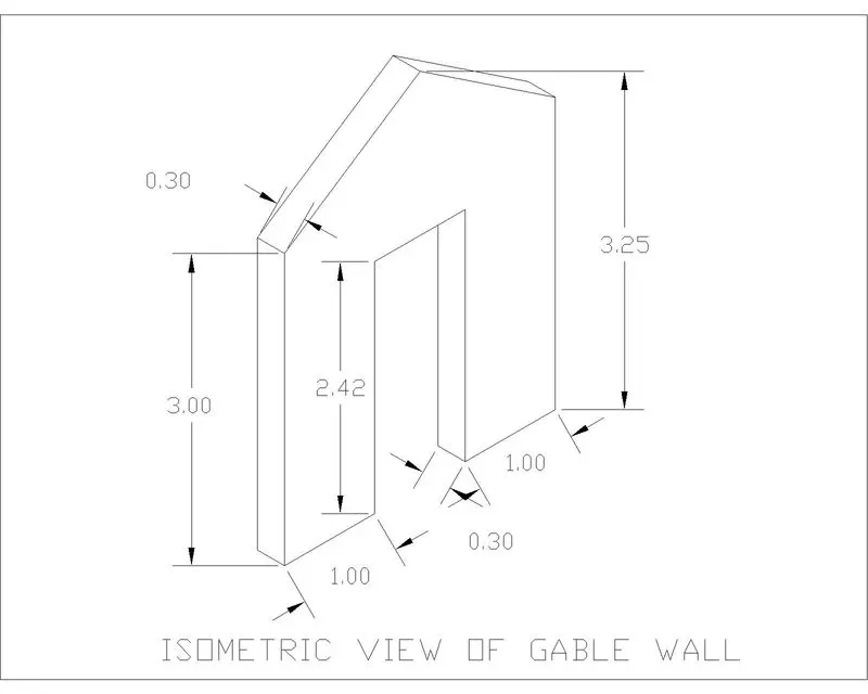
- Mention all the dimentions and then plot layout to take print.
RESULT:
C.S OF LOAD BEARING WALL OVER SPREAD FOOTING:
C.S ISOLATED FOOTING:
LINE DIAGRAM OF A TWO BEDROOM BUILDING:
C.S OF LOAD BEARING WALL SHOWING FOUNDATION DETAILS:
ISOMETRIC VIEW OF STEPS:
ISOMETRIC VIEW OF GABLE WALL: