Creating Levels, Grids, Layout and model elements for a residential unit using REVIT
ANS 1)
Aim: Defining BIM and Summarize the features of BIM and benefits of using BIM over 2D CAD tools.
- BIM stands for Building Information Modelling.
- It is a visual representation of physical and functional characteristics of a facility from inception onwards. such as, it serves as a shared informatonrepository for collaboration throughout a facility's life cycle. - Features of BIM:
-Easy access to information
-Making the process more expressive
-Comprehesive view of project. - Benefits of BIM
-Complete representation
-Instant updates
-Time constraint
-Resource tracking.
ANS 2)
Aim: Defining the concept of Categories, Families, Elements, Instances in Revit.
- Categories:
- Families:
- Elements:
- Instances:
Choosing a category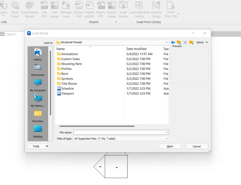
Picking a family and element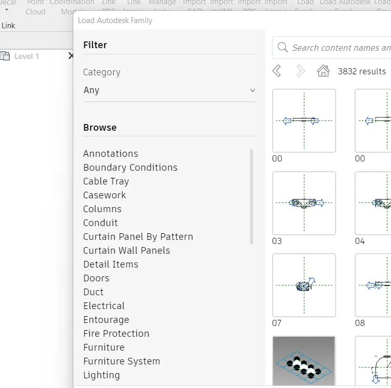
Inserting a instance in a REVIT model
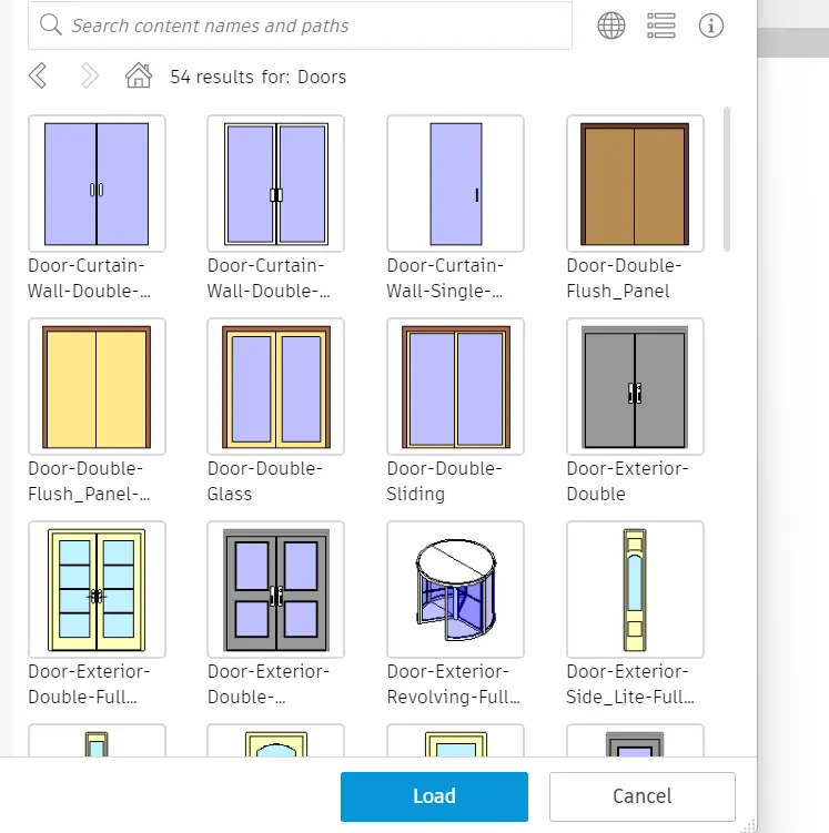
ANS 3)
Aim: Open a project file with architectural template. Save the file with appropriate name. Set up the project units to Imperial / Metric based on your convenience of modelling. Complete the project information under Manage tab. Set up the maximum backups for project file to 3.
Procedure:
- Open the REVIT software by double clicking on it.
- On the left side, in the models section NEW option is available click on it.
- Similiarly at the top left corner there is File menu click on it and select the new file.
- Select architectural template press ok.
- Again go to the file menu and select the Save option.
- Give the name to the project as "Challenge 2" and click on the save option.
Project information under manage tab:
- Select Manage Tab > Go to the Project information
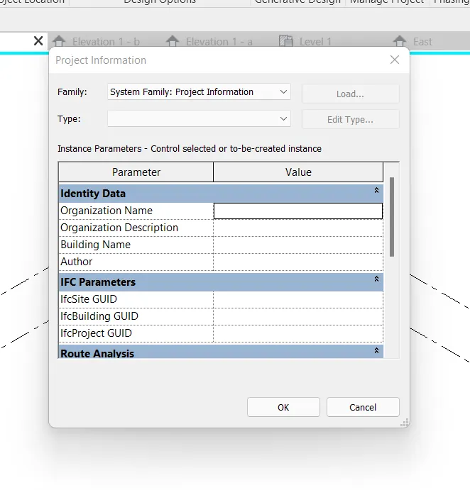
- Fill the details in this tab and press OK.
Set up the maximum backups for project file to 3:
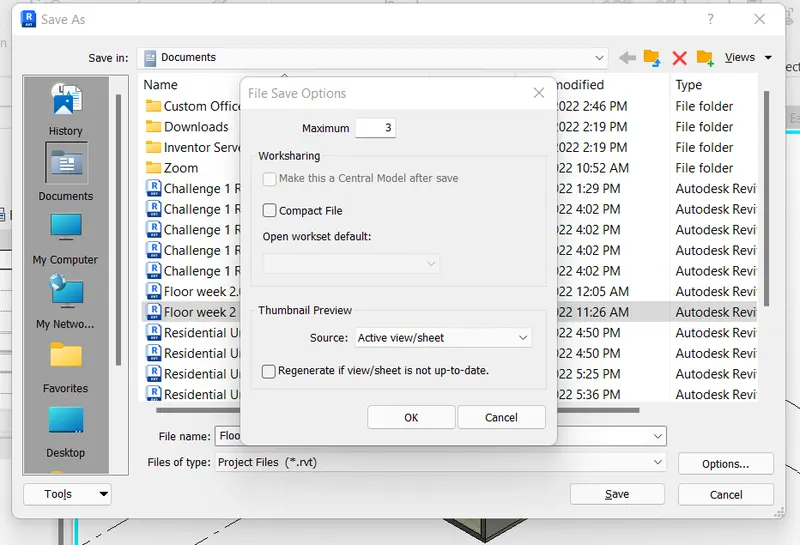
- Go to file tab> click on save as> click on option>Maximum backup.
- Set maximum backup as 3.
- Click Ok and than Click save.
ANS 4)
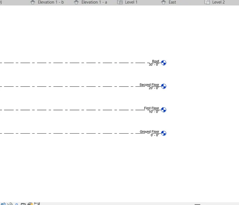
Aim: Understand the concept of Levels and Grids. Follow the naming and conventions. Create the following Levels.
Procedure:
- Select the elevation view first.
- In the architecture tab there is option for the level, click on it.
- Now select the option Pick line and give offset as 10'.
- Pick level 2 as option and click on it and level 3 is created.
- Again do same and pick level 3 as base line level 4 is created.
- Now rename all the level as per the requirements.
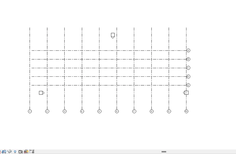
In the architecture tab select the Grid option
Click on the Line option and Draw the grid horizontally
Press ESC and rename the grid by double clicking on it as A.
Again Select the GRID option and now choose Pick line option and give offset as 10' and pick the lines.
Similiarly Select the GRID but now draw longitudinal Grids and Give the offset as 20' and press esc to finish.
ANS 5)
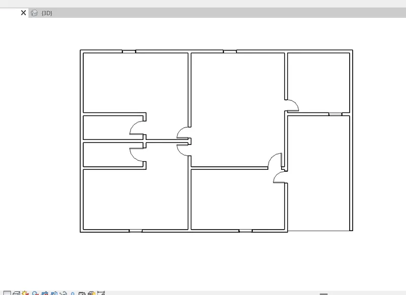
Aim: 3D modelling of residential unit.
Procedure:
- Select the Architectural tab and click on the floor option in it.
- After selecting the floor click on the rectangle option .
- Draw the floor 0f 60'x40' and press ESC.
- Now Select the WALL option and click on the line option.
- Draw the walls as per the requirements.
ANS 6)
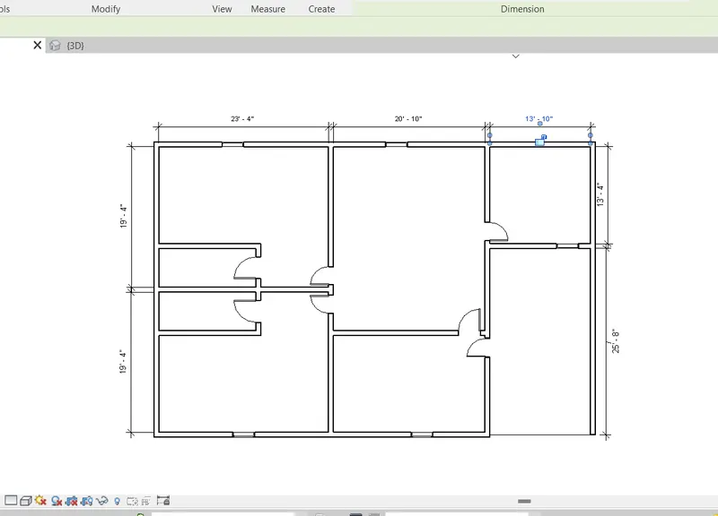
Aim: In the layout created draft the level of details you are planning to include – Dimensions of room, components you plan to add in the residential unit.
Procedure:
- Select the anotate tab for the dimensions.
- Select linear or angular any one of them.
- Now give the dimensions for the layout.
ANS 7)
Aim: Identify the residential model elements such as Door, Windows, Tables, Chair, Couch, Bed, Lamps from the library and insert them to the model .
Procedure:
- In the Architecture tab select the component option.
- In the component option select the place a component option.
- Now go to the Load family option and inside this go to the family select the component and place it in the drawing.
- Select the Table and move it to the model and press esc.
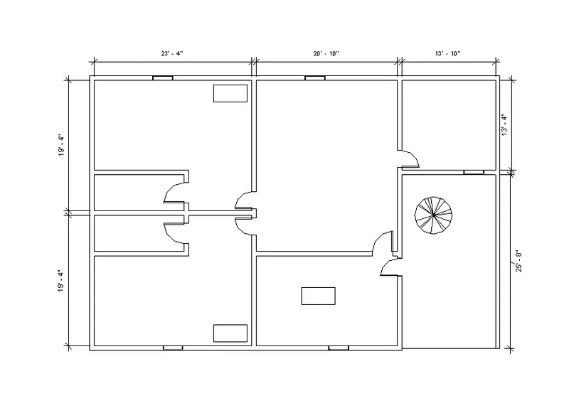
There is some Problem in my system as I am not able to find other components like bed and chair and other.