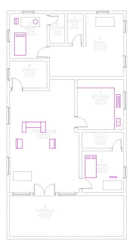
Creating Levels, Grids, Layout and model elements for a residential unit using REVIT
1. Building Information Modelling :
A ) BIM :
BIM is a visual representation of the physical and functional characteristics of a facility from inception onwards. As such, it serves as a shared information repository for collaboration throughout a facility's life cycle.
B ) FEATURES OF BIM :
a) Easy access to information :
- Using revit, we can access all the informations of the building such as,
- The area of the plan.
- Type of materials used in the construction of the building elements like walls and other structures.
- Type of building to be constructed.
- 2D & 3D view of the whole project.
- Interior & Exterior view of the building.
b) Making the process more expressive :
- Using revit, we can make the process of modelling building more expressive in such a way as,
- Through revit, we can work in 5 Dimensional such as Length, breadth, height, Time and cost.
- These helps to make the accurate time and cost required for for the completion of the project.
- Also it helps to create the schedule for the project
- We can express exactly, what type of materials are used in the construction of the building elements.
c) Comphrehensive view of the project :
- Using revit, we can make comphrehensive view of the project such as,
- It is the most important feature of the revit modelling, it enables every components of the project elements to be viewed comphrehensively.
- So, it can be viewed from the geometrical view of the building to the spatial view of the building.
- It also gives the provision of topography and quantity survey of the projects.
C ) BENIFITS OF BIM OVER 2D CAD TOOLS :
a) Complete representation :
- BIM allows to give complete representation of the building, such as
- Plumbing features.
- Electrical features and
- Mechanical features of a buildings.
b) Instant updates :
- In BIM the updates for all the components can be done instantly.
- Like whenever we want to change the existingly created components, then it will be updated instantly.
c) Time constraint :
- In BIM, it allows us to prefabricate the building models easily by adjust the model itself based on the building design.
- So, the time required to change the model as per the buiding model can be avoided.
d) Resource tracking :
- The resource tracking is a key model of a BIM model.
- It allows to figure out how much resources required during the design stage.
- It also helps to improve the flow and effeciency of constructions.
2. The concept of Categories, Families, Elements, Instances in Revit :
AIM :
To understand the concept of Categories, Families, Elements, Instances in Revit.
INTRODUCTION :
- In Revit, we can add the required DOORS, WINDOWS and other architectural elements as desired.
- For that, the concepts of Categories, Families, Elements, Instances should be understand.
- By understanding those concepts we can add the DOORS, WINDOWS and other architectural elements as desired.
PROCEDURE:
- First the building layout should be created in the desired level.
- To add Doors to the created layout, select the "ARCHITECTURE" in the tool bar and select Door < Load family < US < Door (family)
- Likewise to add Windows to the created layout, select the "ARCHITECTURE" in the tool bar and select Windows < Load family < US < Window (family)
RESULT :
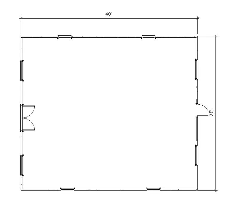
- Here in the result we can see the DOORS and WINDOWS are attached in the layout of challenge 1.
- The various types of elements have been attached from different families and categories in this layout.
3. Setting up a Project :
AIM :
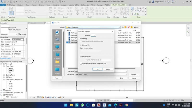
To set up a project by creating project in architectural template, completing project information, setting up maximum backups and saving it with appropriate name in Revit.
INTRODUCTION :
- In Revit, after creating project with architectural template the followings should be completed.
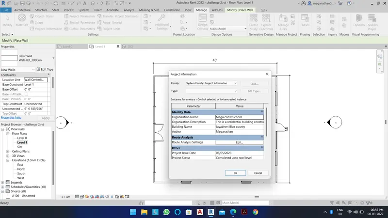
- The project information, here we can fill all the informations of the building which is going to be created.
- Then setting up a maximum backups and saving it with the appropriate name as desired.
PROCEDURE:
- First the building layout should be created in the desired level.
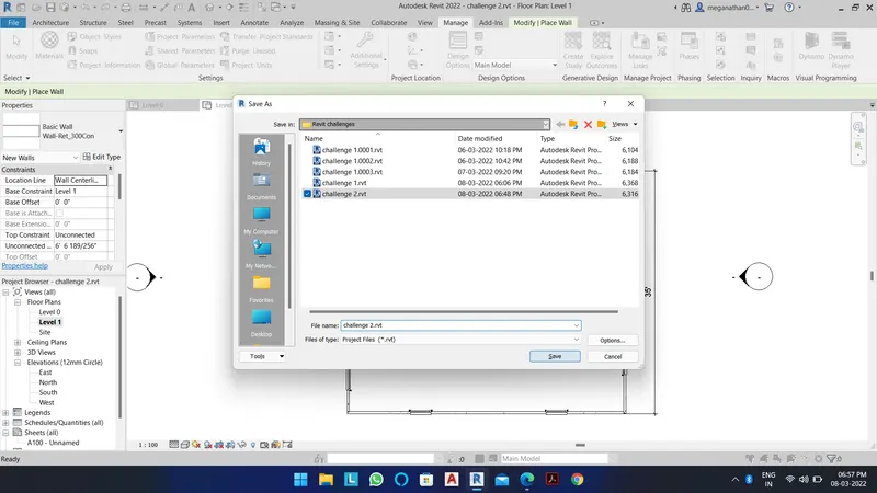
- Then from the MANAGE TAB
- Likewise from the from the FILE MENU
- Atlast the maximum backups of a project file to 3 should be set up.
RESULT :
- Here in the result we can see the project information filled in the created layout.
- Then the maximum backups of a project file to 3 is set up as required.
- At last the created layout is then allowed to save in the appropriate name.
4. The concept of Levels and Grids :
AIM :
To understand the concept of Levels and Grids by following the naming and conventions.
INTRODUCTION :
- In Revit, before the starting to create the building model, the floor levels of the buildings should be created as a transverse line.
- Likewise after completion of the building model then for to make the sections, the grids are made across the building model in both longitudinal and trasverse.
- By understanding those concepts we can create the building model easily with reference to both levels and grids.
PROCEDURE:
A ) LEVELS :
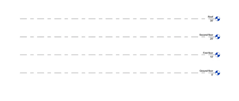
- First the levels should be created as a required heights and renamed as required names before start creating the building model.
- The creations of the levels can only be done in the ELEVATION < EAST and it will be selected from the project browser.
- After selecting the correct view to create the levels of the building, then select ARCHITECTURE TAB < LEVEL < PICK LINE .
- Here, by selecting the existing level line we will be creating the new level line upto the height of 10' from the ground level to the roof upto the 30'after we entering the offset value of 10'.
- These Levels are created only on trasverse direction and renamed as required such as GROUND FLOOR (0'), FIRST FLOOR (10') , SECOND FLOOR (20') and ROOF (30').
B ) GRIDS :
i ) TRANSVERSE GRID :
- To start create the Grid lines, we should change the view of the layout to the PLAN VIEW < LEVEL 1 and it will be selected fom the PROJECT BROWSER.
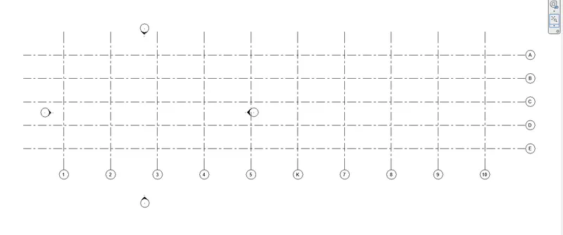
- After selecting the correct view to create the Grids lines, then select ARCHITECTURE TAB < GRID < LINE .
- Here the creation of the Grids should be done in both LONGITUDINAL and TRANSVERSE direction.
- Then we should create first Grid line from the desired point and the other Grids lines are created following by it with the offset of 10' in trasverse direction.
- Atlast the Trasversely created lines then allowed to rename as A,B,C,D,E by double clicking on it.
ii ) LONGITUDINAL GRID :
- Likewise we should create the Grid lines in the longitudinal direction.
- By selecting ARCHITECTURE TAB < GRID < PICK LINE, now by selectin the existingly created Grid line we can offset the other required Grids at the spacing of 20'.
- After selecting the line we should start creating the Grid lines from the desired point of the offset distance of 20'.
- Then the Longitudinaly created lines then allowed to rename as 1 - 10 by double clicking on it.
RESULT :
- Here in the result we can see the both LEVEL LINES and the GRID LINES in both Trasverse and Longitudianl directions.
- The Trasversely created LEVEL lines are allowed to renamed as A,B,C,D,E by double clicking on it.
- Likewise in both Trasversely and Longitudinaly created lines are allowed to renamed as 1 - 10 by double clicking on it.
5. 3D modelling of residential unit :
AIM :
To create a conceptual layout or 3D model of the residential unit in Revit.
INTRODUCTION :
- In Revit, we can create the layout and 3D model of the building.
- Here, we can add the architectural elements such as WALLS, DOORS, WINDOWS and other architectural elements with desired colors, types and dimensions.
- We can also convert the 2D layout to the 3D Model by changing it into the Default 3D view.
- Like we discussed before, we can make LEVEL LINES and the GRID LINES for the building models.
PROCEDURE:
- First the LEVELS of the building should be created upto the roof before starting of the building layout from the PROJECT BROWSER.
- Before start creating the layout of the building the Units of the project should be set as per the project requirements.
- The setting of the units are done by selecting MANAGE TAB < PROJECT UNITS and by selecting appropriate units as required.
- Then the layout should be start to be created from the Ground level to the Roof level by creating the both Exterior and the Interior walls.
- The walls are created after selecting different levels from the Floor plan view in PROJECT BROWSER.
- After creating both Exterior and Interior walls the Doors and Windows are then allowed to add in the walls.
- The Doors are added to the created layout, by selecting the "ARCHITECTURE TAB" in the tool bar and select Door < Load family < US < Door (family)
- Likewise the Windows are added to the created layout, by select the "ARCHITECTURE TAB" in the tool bar and select Windows < Load family < US < Window (family)
RESULT :
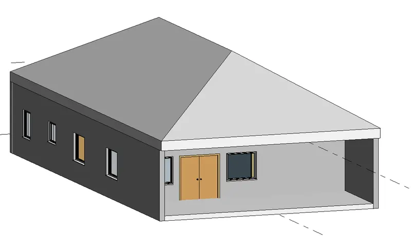
- Here in the result we can see the different types of architectural elements are created in the below model.
- The architectural elements such as WALLS, DOORS and WINDOWS are attached in the created layout.
- The various types of elements have been attached from different families and categories with desired dimensions.
6. Dimensions and components of a plan could be added in the residential unit :
AIM :
To create a the dimensions of the rooms and the components added to the layout of the residential unit in Revit.
INTRODUCTION :
- In Revit, we can create the layout and 3D model of the building.
- Here, we can add the architectural elements such as WALLS, DOORS, WINDOWS and other architectural elements with desired colors, types and dimensions.
- We can also convert the 2D layout to the 3D Model by changing it into the Default 3D view.
- Like we discussed before, we can make LEVEL LINES and the GRID LINES for the building models.
- The created rooms and the components in the layout are can be measured in its dimension with the Annotation Tab.
PROCEDURE:
- First the LEVELS of the building should be created upto the roof before starting of the building layout from the PROJECT BROWSER.
- Before start creating the layout of the building the Units of the project should be set as per the project requirements.
- The setting of the units are done by selecting MANAGE TAB < PROJECT UNITS and by selecting appropriate units as required.
- Then the layout should be start to be created from the Ground level to the Roof level by creating the both Exterior and the Interior walls.
- The walls are created after selecting different levels from the Floor plan view in PROJECT BROWSER.
- After creating both Exterior and Interior walls the Doors and Windows are then allowed to add in the walls.
- The Doors are added to the created layout, by selecting the "ARCHITECTURE TAB" in the tool bar and select Door < Load family < US < Door (family)
- Likewise the Windows are added to the created layout, by select the "ARCHITECTURE TAB" in the tool bar and select Windows < Load family < US < Window (family)
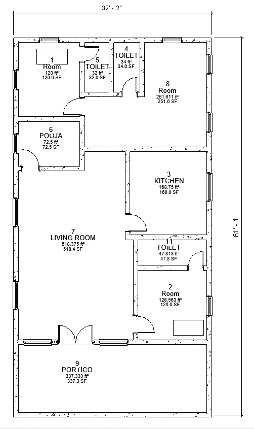
- Then after the complete creation of the building layout, it will be allowed to mark its dimensions of the rooms and the components which are added to it.
- It can be done by selecting the ANNOTATE TAB < LINEAR DIMENSION or ALIGNED DIMENSION.
- Then selecting the corner points of the all components such as walls, doors, windows the dimensions can be marked as required.
RESULT :
- Here in the result we can see the different types of architectural elements are created in the below model.
- The architectural elements such as WALLS, DOORS and WINDOWS are attached in the created layout.
- The various types of elements have been attached from different families and categories with desired dimensions.
- And all the added components and elements are measured and shown its dimension with the Annotation tools.
7. The residential model elements such as Door, Windows, Tables, Chair, Couch, Bed, Lamps from the library :
AIM :
To create residential model elements such as Door, Windows, Table, chair, couch, Bed, Lamps from the library in the created Layout in Revit.
INTRODUCTION :
- In Revit, we can create the layout and 3D model of the building.
- Here, we can add the architectural elements such as WALLS, DOORS, WINDOWS and other architectural elements with desired colors, types and dimensions.
- We can also convert the 2D layout to the 3D Model by changing it into the Default 3D view.
- Like we discussed before, we can make LEVEL LINES and the GRID LINES for the building models.
- The elements from the different families can also be added in the layout if required such as Furnitures .
PROCEDURE:
- First the LEVELS of the building should be created upto the roof before starting of the building layout from the PROJECT BROWSER.
- Before start creating the layout of the building the Units of the project should be set as per the project requirements.
- The setting of the units are done by selecting MANAGE TAB < PROJECT UNITS and by selecting appropriate units as required.
- Then the layout should be start to be created from the Ground level to the Roof level by creating the both Exterior and the Interior walls.
- The walls are created after selecting different levels from the Floor plan view in PROJECT BROWSER.
- After creating both Exterior and Interior walls the Doors and Windows are then allowed to add in the walls.
- The Doors are added to the created layout, by selecting the "ARCHITECTURE TAB" in the tool bar and select Door < Load family < US < Door (family)
- The Windows are also added to the created layout, by select the "ARCHITECTURE TAB" in the tool bar and select Windows < Load family < US < Window (family)
- Likewise the other elements such as furnitures and other landscaping elements can also be inserted inside the created layout.
- Those can be added by selecting ARCHITECTURE TAB < COMPONENT < PLACE A COMPONENT and selecting the required famility, category and instances.
- The required components families such as Table, chair, couch, Bed, Lamps .
RESULT :
- Here in the result we can see the different types of architectural elements are created in the below model.
- The architectural elements such as WALLS, DOORS, WINDOWS, TABLE, CHAIR, COUCH, BED, LAMPS are attached in the created layout.
- The various types of elements have been attached from different families and categories with desired dimensions.