Drafting of various geometries using Chamfer, Fillet tool in AutoCad
AIM AND INTRODUCTION :
AIM :
- To Create a various geometries with fillet, chamfer options in rectangle tool by using AutoCad.
INTRODUCTION :
- The creation of various Geometries are done by using tools such as line tool, fillet tool, chamfer tool, circle tool etc.
- And the required dimensions are mentioned as a start and endpoint of the line.
- For creating the geometry with curved and cross edge then we should enable fillet and chamfer options in rectangle tool, which will be displaying in the comment box after selecting a rectangle tool.
- The different dimensions used are Linear, angular, alignment etc.
PROCEDURE :
1.
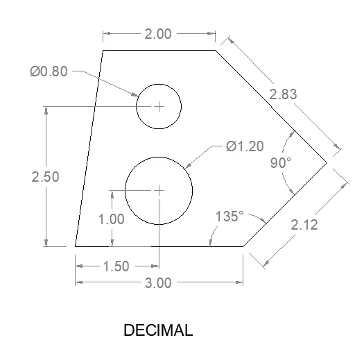
- To draw the above geometry, the starting point should be considered as 0 and end point of the line should be as per the given reference dimension of the line.
- When creating angles should specify symbol '<' with required degree value in Y axis and length value of the line as X axis. Eg: @2.83<225.
- The geometry will be drawn by using the fillet and chamfer options in rectangle tool, and the lengths, widths should be specified as per the required angle and dimensions of the geometry.
- While drawing geometry lines by using the rectangle tool, we should enter the starting and ending point of the rectangle.
- To know whethere the drawn angle and dimensions of the geometry are correct as per the required drawing, we should use the tool called 'Dimlinear' , Dimangular' , 'Dimalignment' etc.
- To save the geometry, we should use the key 'ctrl+s' .
2.
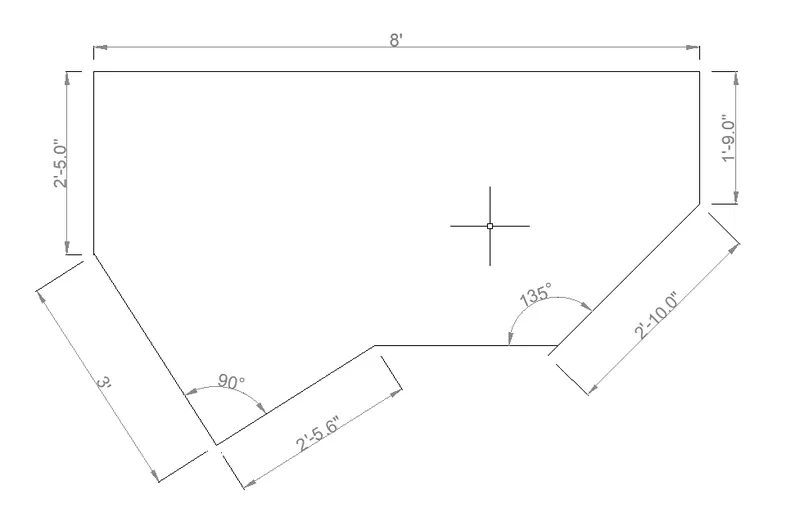
- To draw the above geometry, the starting point should be considered as 0 and end point of the line should be as per the given reference dimension of the line.
- When creating angles should specify symbol '<' with required degree value in Y axis and length value of the line as X axis. Eg: @2'10"<30.
- The geometry will be drawn by using the fillet and chamfer options in rectangle tool, and the lengths, widths should be specified as per the required angle and dimensions of the geometry.
- While drawing geometry lines by using the rectangle tool, we should enter the starting and ending point of the rectangle.
- To know whethere the drawn angle and dimensions of the geometry are correct as per the required drawing, we should use the tool called 'Dimlinear' , Dimangular' , 'Dimalignment' etc.
- To save the geometry, we should use the key 'ctrl+s' .
3.
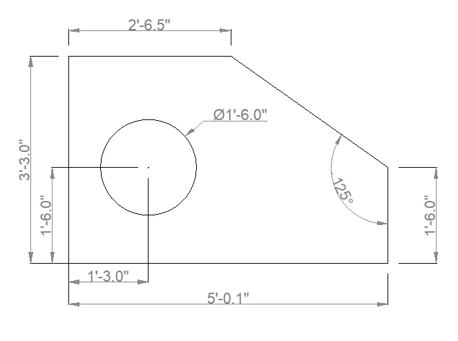
- To draw the above geometry, the starting point should be considered as 0 and end point of the line should be as per the given reference dimension of the line.
- When creating angles should specify symbol '<' with required degree value in Y axis and length value of the line as X axis. Eg: @2'10"<135.
- The geometry will be drawn by using the fillet and chamfer options in rectangle tool, and the lengths, widths should be specified as per the required angle and dimensions of the geometry.
- While drawing geometry lines by using the rectangle tool, we should enter the starting and ending point of the rectangle.
- To know whethere the drawn angle and dimensions of the geometry are correct as per the required drawing, we should use the tool called 'Dimlinear' , Dimangular' , 'Dimalignment' etc.
- To save the geometry, we should use the key 'ctrl+s' .
4.
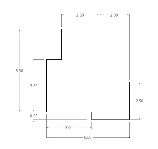
- To draw the above geometry, the starting point should be considered as 0 and and the everry end point of the line should be as per the given reference dimension of the line.
- The geometry will be drawn by using the line tool, and the lengths should be specified as per the required angle and dimensions of the geometry.
- While drawing geometry lines by using the line tool, we should enter the starting and ending point of the rectangle.
- To know whethere the drawn angle and dimensions of the geometry are correct as per the required drawing, we should use the tool called 'Dimlinear' , Dimangular' , 'Dimalignment' etc.
- To save the geometry, we should use the key 'ctrl+s' .
5.
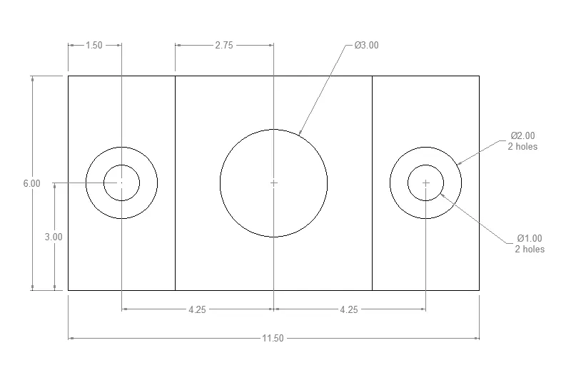
- To draw the above geometry, the starting point should be considered as 0 and end point of the line should be as per the given reference dimension of the line.
- The geometry will be drawn by using the fillet and chamfer options in rectangle tool and circle tool ,the lengths, widths, diameter, radius should be specified as per the required angle and dimensions of the geometry.
- While drawing geometry lines by using the rectangle tool, we should enter the starting and ending point of the rectangle,if it is circle then the center point should be specified.
- To know whethere the drawn angle and dimensions of the geometry are correct as per the required drawing, we should use the tool called 'Dimlinear' , Dimangular' , 'Dimalignment' etc.
- To save the geometry, we should use the key 'ctrl+s' .
6.
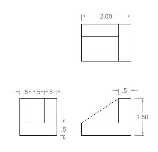
- To draw the above geometry, the starting point should be considered as 0 and end point of the line should be as per the given reference dimension of the line.
- The geometry will be drawn by using the fillet and chamfer options in rectangle tool, and the lengths, widths should be specified as per the required angle and dimensions of the geometry.
- While drawing geometry lines by using the rectangle tool, we should enter the starting and ending point of the rectangle.
- To know whethere the drawn angle and dimensions of the geometry are correct as per the required drawing, we should use the tool called 'Dimlinear' , 'Dimalignment' etc.
- To save the geometry, we should use the key 'ctrl+s' .
7.
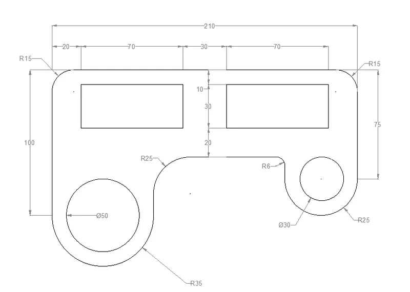
- To draw the above geometry, the starting point should be considered as 0 and end point of the line should be as per the given reference dimension of the line.
- The geometry will be drawn by using the fillet and chamfer options in rectangle tool and circle tool, the lengths, widths should be specified as per the required angle and dimensions of the geometry.
- While drawing geometry lines by using the rectangle tool, we should enter the starting and ending point of the rectangle, if it is circle then the center point should be specified.
- To know whethere the drawn angle and dimensions of the geometry are correct as per the required drawing, we should use the tool called 'Dimlinear' , Dimangular' , 'Dimalignment' etc.
- To save the geometry, we should use the key 'ctrl+s' .
8.
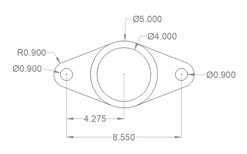
- To draw the above geometry, the starting point should be considered as 0
- The geometry will be drawn by using the fillet and circle tool, and the radius, diameter should be specified as per the required dimensions of the geometry.
- While drawing geometry lines by using the fillet option and circle tool, we should mention the center point of the circle.
- To know whethere the drawn angle and dimensions of the geometry are correct as per the required drawing, we should use the tool called 'Dimlinear' , 'Dimradius', 'Dimdiameter' etc.
- To save the geometry, we should use the key 'ctrl+s' .
9.
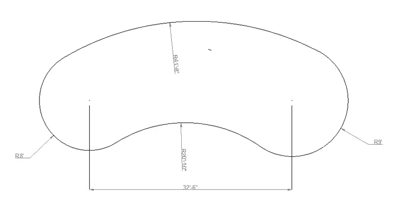
- To draw the above geometry, the starting point is considered and two circles are drawn as Radius 8' and 9' at a distance of 32' 6".
- The geometry will be drawn by using the circle tool, and the radius, diameter should be specified as per the required dimensions of the geometry.
- While drawing geometry circles by using a circle tool, we should enter the starting and ending point of the circle if the circle should be placed between two tangent.
- To know whethere the drawn angle and dimensions of the geometry are correct as per the required drawing, we should use the tool called 'Dimlinear', 'Dimradius', 'Dimdiameter' etc.
- To save the geometry, we should use the key 'ctrl+s' .
10.
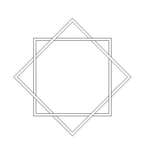
- To draw the above geometry, the length of the rectangle is specified as 30' and the width as 30' to make an square geometry.
- For the thickness of a rectangle, the offset option is used as value 1'.
- The rectangle which is drawn <45 and fitted in the same center point of the previous rectangle to get this following geometry.
- Also some of the Intersecting lines are trimed by using the trim tool.
- To save the geometry, we should use the key 'ctrl+s' .
11.
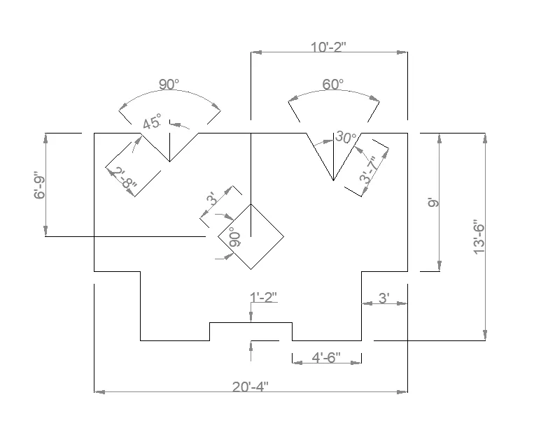
- To draw the above geometry, the starting point should be considered as 0 and end point of the line should be as per the given reference dimension of the line.
- When creating angles should specify symbol '<' with required degree value in Y axis and length value of the line as X axis. Eg: @3'7"<30.
- The geometry will be drawn by using the line tool, and the lengths should be specified as per the required angle and dimensions of the geometry.
- While drawing geometry lines by using the line tool, we should enter the starting and ending point of the line.
- To know whethere the drawn angle and dimensions of the geometry are correct as per the required drawing, we should use the tool called 'Dimlinear' , Dimangular' , 'Dimalignment' etc.
- To save the geometry, we should use the key 'ctrl+s' .
RESULTS :
1.
2.
3.
4.
5.
6.
7.
8.
9.
10.
11.