Creating a Floor plan, Footing detail and Isometric view using AutoCad
AIM AND INTRODUCTION :
i ) AIM:
To Create a Floor plan, Footing detail and Isometric view with line tool and isometric drafting option by using AutoCad.
ii ) INTRODUCTION :
The creation of the Geometries are mostly done by the tool called line tool.
And the required dimensions are mensioned as a start and endpoint of the line.
But while creating the isometric geometries, we should enable a isometric drafting tool, which will be located at the status bar.
To changing the isometric geometry view direction, we can change isoplane directions such as left,right,top.
PROCEDURE :
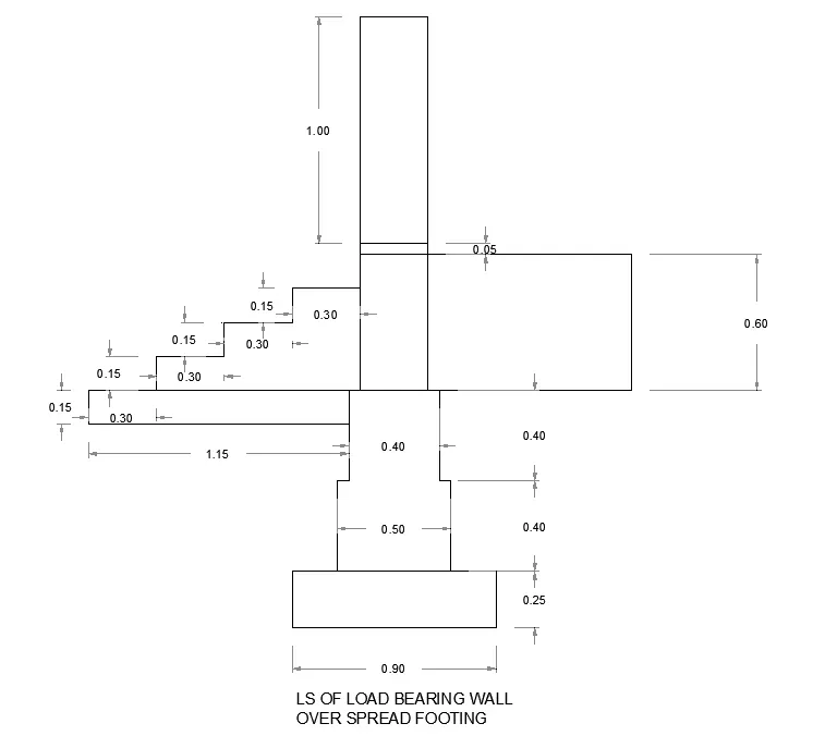
1. LS OF LOAD BEARING WALL OVER SPREAD FOOTING :
- To draw the 'LS OF LOAD BEARING WALL OVER SPREAD FOOTING' , the starting point should be considered as 0 and end point of the line should be as per the given reference dimension of the line.
- The geometry will be drawn by using the line tool and the lengths should be specified as per the required angle and dimensions of the geometry.
- While drawing geometry lines by using the line tool, we should enter the starting and ending point of the line. Eg: In this above drawing the base line start point is 0 and the end point value is 0.9 .
- To know whethere the drawn angle and dimensions of the geometry are correct as per the required drawing, we should use the tool called 'Dimlinear' , Dimangular' , 'Dimalignment' etc.
- To save the geometry, we should use the key 'ctrl+s' .
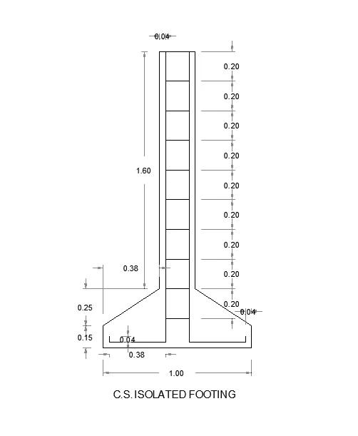
2. CS ISOLATED FOOTING :
- To draw the 'CS ISOLATED FOOTING' , the starting point should be considered as 0 and end point of the line should be as per the given reference dimension of the line.
- The geometry will be drawn by using the line tool and the lengths should be specified as per the required angle and dimensions of the geometry.
- While drawing geometry lines by using the line tool, we should enter the starting and ending point of the line. Eg: In this above drawing the base line start point is 0 and the end point value is 1.00 .
- To know whethere the drawn angle and dimensions of the geometry are correct as per the required drawing, we should use the tool called 'Dimlinear' , Dimangular' , 'Dimalignment' etc.
- To save the geometry, we should use the key 'ctrl+s' .
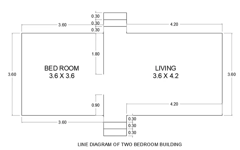
3. LINE DIAGRAM OF TWO BEDROOM BUILDING :
- To draw the 'LINE DIAGRAM OF TWO BEDROOM BUILDING' , the starting point should be considered as 0 and end point of the line should be as per the given reference dimension of the line.
- The geometry will be drawn by using the line tool and the lengths should be specified as per the required angle and dimensions of the geometry.
- While drawing geometry lines by using the line tool, we should enter the starting and ending point of the line. Eg: In this above drawing the base line start point is 0 and the end point value is 3.60,0.3,4.20 .
- To know whethere the drawn angle and dimensions of the geometry are correct as per the required drawing, we should use the tool called 'Dimlinear' , Dimangular' , 'Dimalignment' etc.
- To save the geometry, we should use the key 'ctrl+s' .
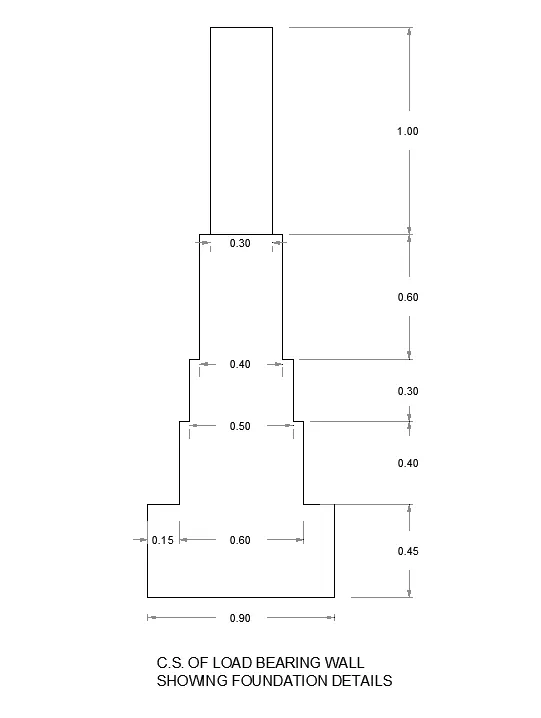
4. CS OF LOAD BEARING WALL SHOWING FOUNDATION DETAILS :
- To draw the 'CS OF LOAD BEARING WALL SHOWING FOUNDATION DETAILS' , the starting point should be considered as 0 and end point of the line should be as per the given reference dimension of the line.
- The geometry will be drawn by using the line tool and the lengths should be specified as per the required angle and dimensions of the geometry.
- While drawing geometry lines by using the line tool, we should enter the starting and ending point of the line. Eg: In this above drawing the base line start point is 0 and the end point value is 0.9 .
- To know whethere the drawn angle and dimensions of the geometry are correct as per the required drawing, we should use the tool called 'Dimlinear' , Dimangular' , 'Dimalignment' etc.
- To save the geometry, we should use the key 'ctrl+s' .
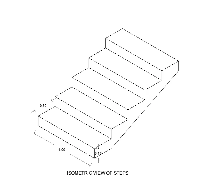
5. ISOMETRIC VIEW OF STEPS :
- To draw the 'ISOMETRIC VIEW OF STEPS' , the starting point should be considered as 0 and end point of the line should be as per the given reference dimension of the line.
- But while creating the isometric drawing, we should enable a isometric drafting tool, which will be located at the status bar.
- The geometry will be drawn by using the line tool and the lengths should be specified as per the required angle and dimensions of the geometry.
- While drawing geometry lines by using the line tool, we should enter the starting and ending point of the line. Eg: In this above drawing the base line start point is 0 and the end point value is 1.0 .
- To know whethere the drawn angle and dimensions of the geometry are correct as per the required drawing, we should use the tool called 'Dimlinear' , Dimangular' , 'Dimalignment' etc.
- To save the geometry, we should use the key 'ctrl+s' .
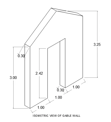
6. ISOMETRIC VIEW OF GABLE WALL :
- To draw the 'ISOMETRIC VIEW OF GABLE WALL' , the starting point should be considered as 0 and end point of the line should be as per the given reference dimension of the line.
- But while creating the isometric drawing, we should enable a isometric drafting tool, which will be located at the status bar.
- The geometry will be drawn by using the line tool and the lengths should be specified as per the required angle and dimensions of the geometry.
- While drawing geometry lines by using the line tool, we should enter the starting and ending point of the line. Eg: In this above drawing the base line start point is 0 and the end point value is 1.0, 1.0, 1.0 .
- To know whethere the drawn angle and dimensions of the geometry are correct as per the required drawing, we should use the tool called 'Dimlinear' , Dimangular' , 'Dimalignment' etc.
- To save the geometry, we should use the key 'ctrl+s' .
RESULT :
1.
2.
3.
4.
5.
6.