Creating Levels, Grids, Layout and model elements for a residential unit using REVIT
1) What is BIM? Summarize the features of BIM and benefits of using BIM over 2D CAD tools.
Building Information Modeling (BIM) is the foundation of digital transformation in the architecture, engineering, and construction (AEC) industry. As the leader in BIM, Autodesk is the industry's partner to realize better ways of working and better outcomes for business and the built world.
Building Information Modeling (BIM) is the holistic process of creating and managing information for a built asset. Based on an intelligent model and enabled by a cloud platform, BIM integrates structured, multi-disciplinary data to produce a digital representation of an asset across its lifecycle, from planning and design to construction and operations.
FEATURES OF BIM:
- COLLABORATION
- SUSTAINABILITY
BIM is a physical representation of the physical and functional characteristics of the building process, that provides every minute detail of the project. Every stakeholder makes their discipline-specific input to make it a comprehensive shared information resource about the structure. One can easily access the right information at the right time that provides a reliable basis for decision making during a structure’s entire lifecycle.
BIM models not only present 3D geometric view of the structure, they provide a more comprehensive overview of the entire building process. It covers every component of this process from geometrical aspect of the design to spatial relationships,from light analysis to provision of various services,from topographical information to quantities or properties of building components, and so on.
ADVANTAGES OF BIM OVER 2D CAD:
There are multiple advantages working with the BIM methodology and therefore by using BIM oriented software, let’s see some of those which are almost universally recognized:
- TIME SAVING
The great efficiency of using a BIM software means that the designer can concentrate more on the creativity aspects of a project without having to constantly worry about updating a multitude of line entities throughout the entire project. This translates into an incredible increase in productivity because each object, chosen from a BIM objects menu, already comes with a set of pre-defined information that can provide useful data for calculating project cost, thermal performance aspects, maintenance, structural, etc.).
All this leads to a considerable saving of time.
- Drastic reduction of Errors
Within a BIM design procedure, floor plans, elevation views and section views are simply different views of the same object. All views can be observed according to specific design phases. Whenever there's a change somewhere in the project, these changes seamlessly affect all other related documents.
As an example, by simply changing the external finish of a facade element, this causes a modification in the wall's transmittance value, its cost and even its structural load.
This allows the technician to avoid mistakes and be sure to have all drawings aligned with the latest project revisions wherever and whenever they are introduced.
- Simplicity at its best
Thanks to the use of BIM technology, even complex models become easy to generate.
Architects can start to push their design capabilities even further proposing ideas that they wouldn't even have imagined doing using traditional 2D CAD tools.
- Integration with other design aspects
BIM definitely expands design horizons. The 3D BIM model can in fact be enriched by a series of additional information that allow full integration with:
• structural calculation
• energy performance calculations
• construction estimating
• technical installations
• maintenance and facility management
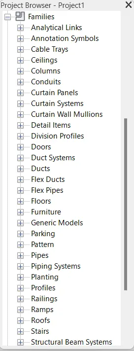
2) Understand the concept of Categories, Families, Elements, Instances in Revit. Go to Insert Tab, choose a category. Pick a family and element. Understand the instances and insert it to Revit model.
CATEGORY:
A category is the one which controls the organization, visibility, graphical representation, scheduling options of family in parent project.
FAMILY:
Family os a group of 2D/3D information that serves to represent a building or documentation element in the project.
INSTANCE:
Instance is an individual representation of a type in the project defined by unique parametric, graphical, and documentation characteristics which makes it unique from other instances in the project.
ELEMENT:
Everything in the revit is classified has Element.
FAMILY IS FURTHUR CLASSIFIED INTO THREE TYPES:
i. ELEMENTS
ii. CLASSES
iii. SUB-CLASSES
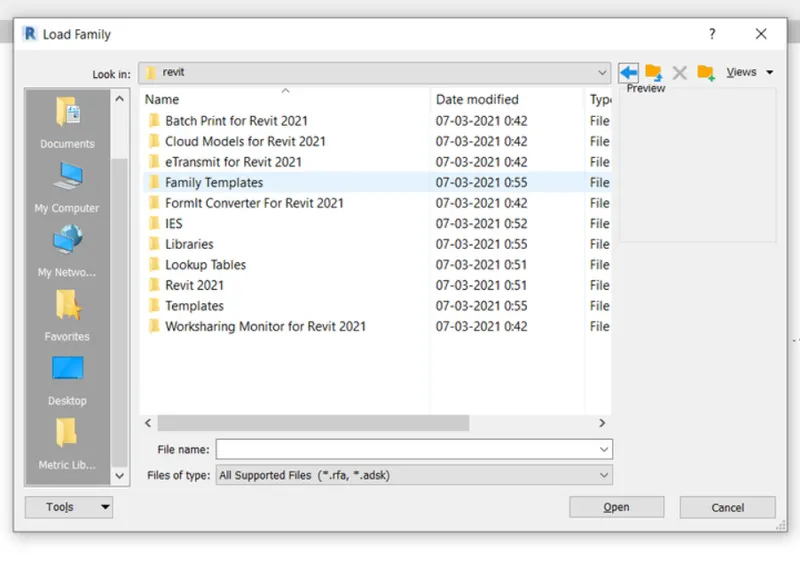
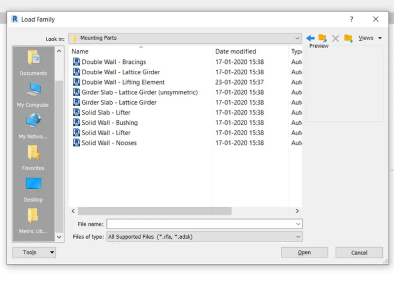
To load the family in REVIT is shown below,
Select Insert tab.

Select option load family.

Select the family to load in revit.
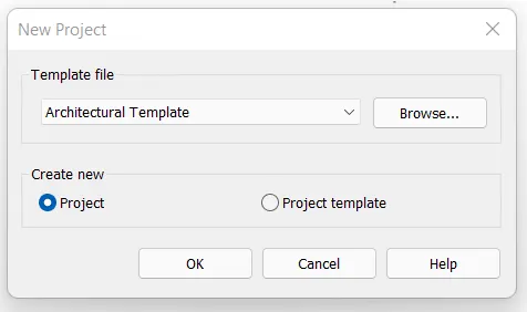
3) Setting up a Project – Open a project file with architectural template. Save the file with appropriate name. Set up the project units to Imperial / Metric based on your convenience of modelling. Complete the project information under Manage tab. Set up the maximum backups for project file to 3.
Architecture template:
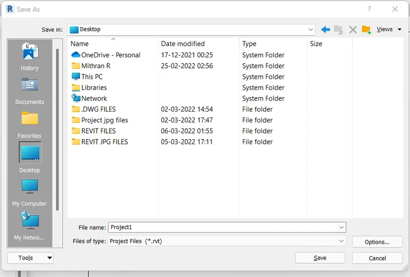
Saving an project with appropriate name - PROJECT1:
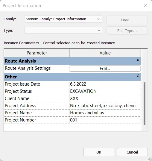
Project information:
Go to manage toolbar.
Select project information.
4) Understand the concept of Levels and Grids. Follow the naming and conventions. Create the following Levels: ( Convert to metric equivalents if metric is your units)
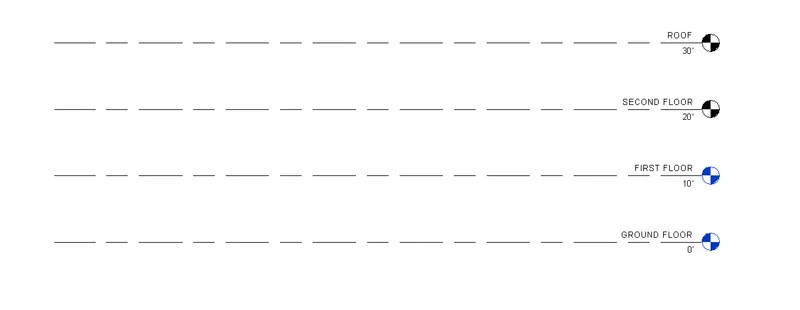
Ground Floor @ 0’
First Floor @ 10’
Second Floor @ 20’
Roof @ 30’
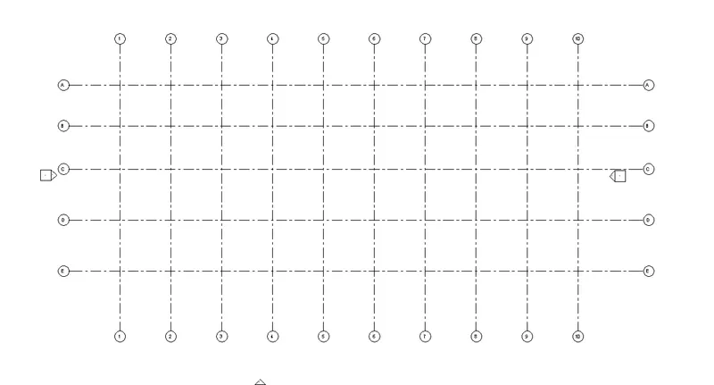
Grids Transverse Grids A, B,C,D, E @ 10’ spacing
Longitudinal Grids from 1 to 10 @ 20’ spacing.
Creating different levels in REVIT.
Open Revit.
Open Architecture template and select project.
Change units to feet and inches.
Now go to view tab - select elevation.
In project browser select - elevation - east.
Two basic level will be displayed on screen.
Keep the bottom level and delete the other one.
Rename it as Groung level.
Now go to modify tab - select copy.
Copy the source line to 10', 20', 30' respectively.
Rename the others levels as first floor, second floor, roof.
Creating grids in REVIT:
Open Architecture template and select project.
Change units to feet and inches.
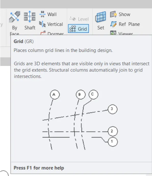
Go to Architecture tab and select grid options.
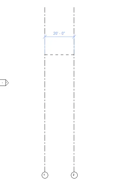
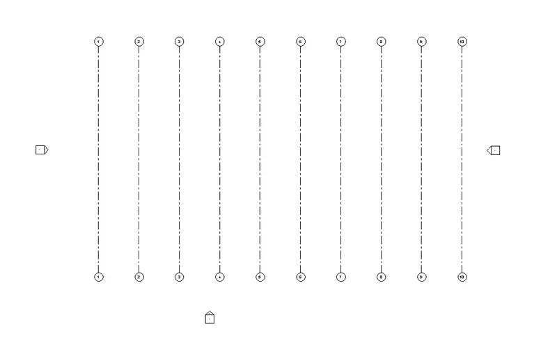
Draw the grid in vertical manner and name it has 1.
Copy the grid from modify tab and paste it at spacing of 20'.
Draw the grids inserting the vertical grids in same manner and name it as A,B,C,D,E.
Vertical Grids at 20' spacing.
5) 3D modelling of residential unit – From looking at your house / or a place you aspire. Create a conceptual layout of the residential unit. You can measure using a tape or
you can access your residential plan to create a similar layout.
Open REVIT with architecture template.
Use feet as desired units.
Type UN for units dialogue box.
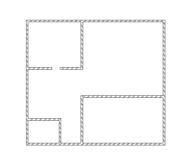
Go to Architecture tab - select wall.
Draw External walls and internal walls by changing the properties of wall settings.
6) In the layout created draft the level of details you are planning to include – Dimensions of room, components you plan to add in the residential unit.
Open REVIT with architecture template.
Use feet as desired units.
Type UN for units dialogue box.
Go to Architecture tab - select wall.
Draw External walls and internal walls by changing the properties of wall settings.
Go to Annotate tab - select text to name the rooms.
Go to modify and selection linear dimension for dimension.
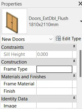
For Doors - Go to Architecture tab - select door.
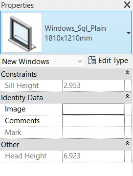
For Windows - Go to Architecture tab - select window.
In view tab - select 3D VIEW.
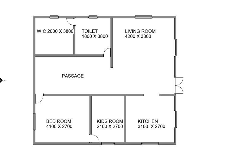
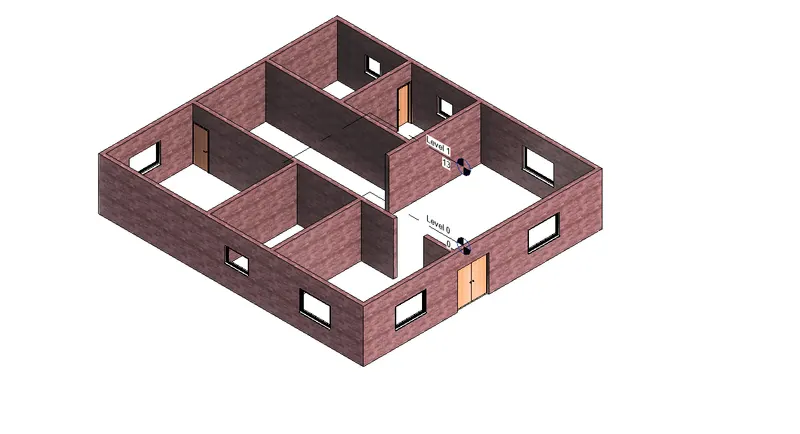
7) Identify the residential model elements such as Door, Windows, Tables, Chair, Couch, Bed, Lamps from the library and insert them to the model . Save the project for use
for Assignment 3.
DOOR DETAILS:
WINDOW DETAILS:
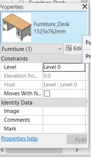
FURNITURE DETAILS:
FINAL OUTPUT: