Creating a Floor plan, Footing detail and Isometric view using AutoCad
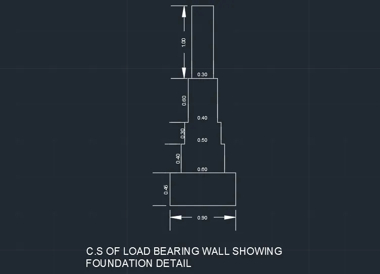
CROSS SECTION OF LOAD BEARING WALL SHOWING FOUNDATION DETAILS
AIM:
To draw c/s of load bearing wall showing foundation details.
COMMANDS USED:
- Line
- Offset
- Trim
PROCEDURE:
- Create line by typing “L” in command box.
- Point the cursor at any desired point for length and type @0.90,0 and offset it at opposite side
- Again, for width mention @0,0.45 and offset it at opposite side
- Specify next points and use offsets for required segments
- Use trim option by typing “TR” command box, erase the unwanted segments where ever it is necessary
- Create dimensions by selecting in Ribbon section or by typing “Dim” in command box for the required length, width and spacing.
RESULT: The c/s of load bearing wall showing foundation details is drawn.
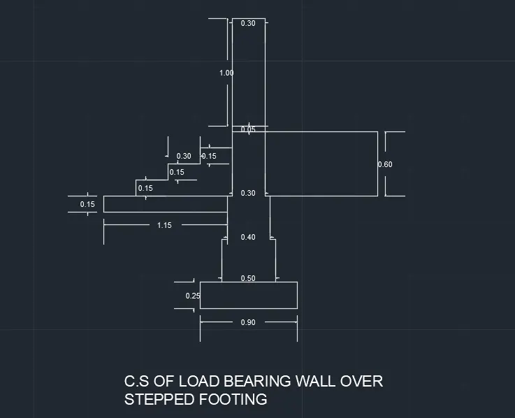
CROSS SECTION OF LOAD BEARING WALL OVER STEPPED FOOTING
AIM:
To draw c/s of load bearing wall over stepped footing
COMMANDS USED:
- Line
- Rectangle
- Trim
PROCEDURE:
- Create rectangle by typing “rec” in command box.
- Specify length of rectangle as 0.9 units in command box
- Specify width of rectangle as 0.25 units in command box
- Create another rectangle of desired length and width as required in command box and repeat the process
- Draw lines by typing “L” in command box or from tool bar where ever line is required to be drawn.
- Use trim option by typing “TR” command box, erase the unwanted segments where ever it is necessary
- Create dimensions by selecting in Ribbon section or by typing “Dim” in command box for the required length, width and spacing.
RESULT: The c/s of load bearing wall over stepped footing is drawn
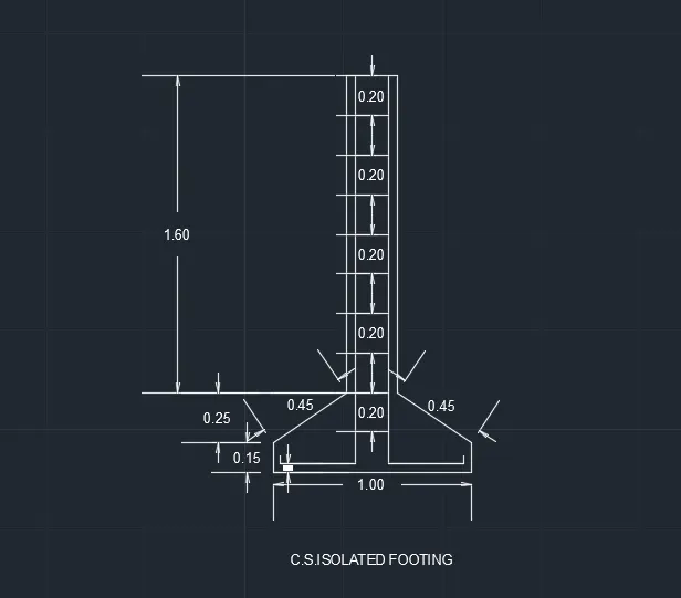
CROSS SECTION OF AN ISOLATED FOOTING
AIM:
To draw c/s of an isolated footing
COMMANDS USED:
- Line
- offset
- Trim
PROCEDURE:
- Create line by typing “L” in command box and give 1 units
- By using relative coordinates by typing ‘L’ in command box and enter @0,0.15
- Give the next command as @0.38,0.25
- Next coordinate is given as @0,1.6
- Repeat the same process until bottom portion is attained
- Draw offset by typing ‘O’ in command box and offset the segments where ever it is necessary
- Trim the unwanted lines.
RESULT: The c/s of an isolated footing is drawn.
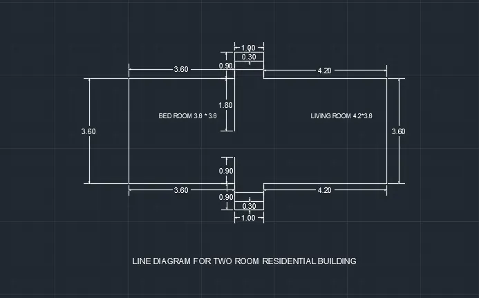
LINE DIAGRAM FOR TWO BEDROOM BULIDING
AIM: To draw line diagram for two bedroom building
COMMANDS USED:
- Line
- Rec
- offset
- Trim
PROCEDURE:
- Create a rectangle of size (8.2*3.6)
- Type ‘o’ in command box and specify the distance of 3.6 units for left bottom end
- Draw an offset using command ‘o’ and specify the distance of 4.2 units from left bottom end.
- For steps offset for value 0.3 and 1 units respectively for both top and bottom of the rooms.
- Trim the unwanted lines.
- Using command line draw a line at a distance of 3.2 units from left bottom end to upwards 0.9 units
- Using command line draw a line at a distance of 3.2 units from left bottom end to downwards 1.8 units
RESULT: The line diagram for two-bedroom building is drawn.
ISOMETRIC VIEWS FOR STEPS
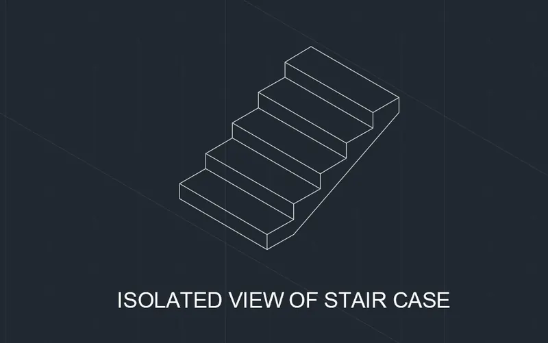
AIM:
To draw isometric views for steps.
COMMANDS USED:
- Line
- Isometric planes
PROCEDURE:
- To work with isometric view, in command type ‘ds’ - snap off, grid off. Put isometric view on.
- Ortho mode should be on
- Now by ‘l’ command move the cursor to x- axis and give one unit and offset it at a distance above for 0.15
- From that point take line command and use polar coordinates of @30<30
- Repeat the process until 4 steps are achieved.
RESULT: The steps are drawn in isometric view.
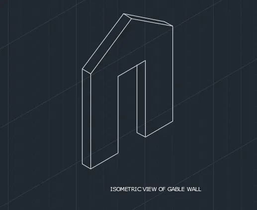
ISOMETRIC VIEWS FOR GABLE WALL
AIM:
To draw isometric views for gable walls.
COMMANDS USED:
- Line
- Isometric planes
PROCEDURE:
- To work with isometric view, in command type ‘ds’ - snap off, grid off. Put isometric view on.
- Ortho mode should be on
- Now by ‘l’ command move the cursor to x- axis and give one unit
- Pointing the cursor upward give 3units.
- Draw 0.3 units to left and 3 units downwards and 0.3 units to left.
- Draw 0ne unit towards right side and 2.42 units downwards.
- Using line command draw 0.3 units to left side and draw a line which intersects the top side.
- Repeat the process until right downward is achieved
- Draw vertical line with ortho on @0.3 and join vertical line using line from left and right end same the process explained above
- Remove unwanted lines by using trim or erase.
RESULT: The Isometric views for gable wall is drawn.