Creating a Residence Layout, Seating plan, Toilet and Utility room plan using AutoCad
1. Creating a Residence Layout, Seating plan, Toilet and Utility room plan using AutoCAD
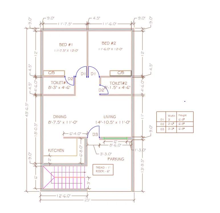
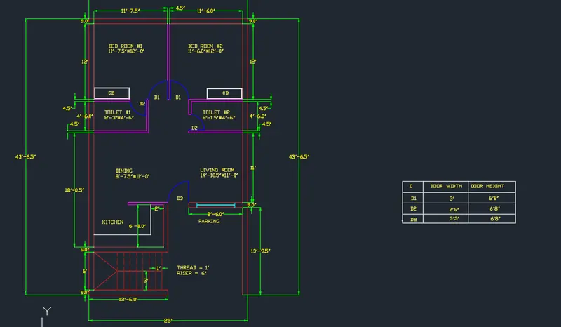
- AIM: To draw the layout of the residential plan as shown below
- INTRODUCTION:
The above fig. Consists of following units such as,
Two Bedrooms
Two Toilets
A living room
A kitchen
A dining room
Parking Area
Staircase Area
- PROCEDURE:
Click on AutoCAD application and run the file
Type QNEW in command box
Select default settings as Imperial (Feet and Inches) and press enter
Keep ortho on
Type UN in command box for unit's settings
Select Engineering as unit type
Precisions as 0’-0.0”
Type limits in command box and enter 0,0 as first left corner values
And 50’,50’ as upper right corner values
Enter Z and A enter in command box for zoom all
Now draw the required length in X line and Y line respectively as shown in fig.
Offset the areas where ever it is required
Trim the unwanted lines
Leave the places for door and windows as per its dimension shown in fig.
Give the offsets for Stair case as shown in fig.
Give the text and dimensions as per the fig.
To draw the door
Take the parallel line at the distance of 1”
Take offset of that line to 0.5”
Take a circle and draw as per the required width
Trim the unwanted part
Then the doors of required rooms will be ready
Similarly draw for all the doors
Cupboards are created by giving offset of 5” at all the corners by assuming size of 5’7.3” x 1’9.6”
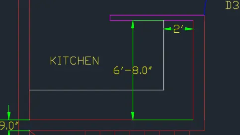
Kitchen slab is created by giving offset of 2’ and unwanted portions are trimmed
Click on layer properties
Color can be automatically selected for required sections such as boundary line, partition walls, doors, windows, text, dimensions, staircase, cupboards, etc.
Click on line type and line color to change the color and type of the required portion
Select load
Select line type as ACAD_ISO02W100 and press ok
Select the stairs which have to be shown as dotted line type as ACAD _ISO02W100
Keep all the layers on for displaying the color of all regions
The layout of the residential plan is ready
- RESULTS:
FOR BEDROOM AND TOILET

FOR REMAINING PART
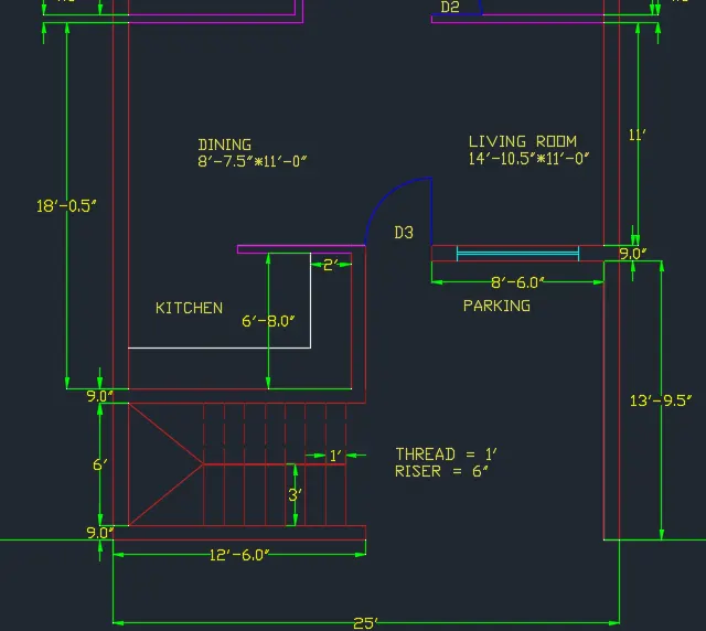
FOR STAIRCASE
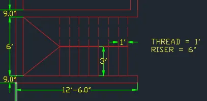
FOR KITCHEN
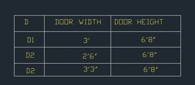
FOR DOOR SCHEDULE
FOR TOTAL RESIDENTIAL PLAN
2 . OUTDOOE SEATING WITH CANOPY
- AIM: To sketch the seating plan for an outdoor canopy
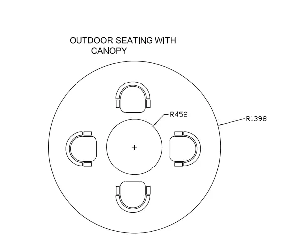
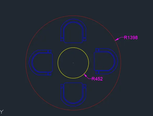
- INTRODUCTION: The outdoor canopy seating consists of one round table of radius 452mm and another and four chairs around the radius of 1398mm
- PROCEDURE:
Click on AutoCAD application and run the file
Type QNEW in command box
Select default settings as METRIC and press enter
Keep ortho on
Type UN in command box for unit's settings
Select Decimal as unit type
Precisions as 0
Type limits in command box and enter 0,0 as first left corner values
And 2000,2000 as upper right corner values
Enter Z and A enter in command box for zoom all
Keep all the object snaps on
Take circle command
Specify and draw two circles of radius 452mm and 1398mm respectively
Now for chair assume the size and copy the image for others
Rotate the chair at 90dg, 180dg, 270dg respectively
Now draw the required length in X line and Y line respectively as shown in fig.
Offset the areas where ever it is required
Trim the unwanted lines
Now move all these chairs at required positions as shown in result
- RESULT:
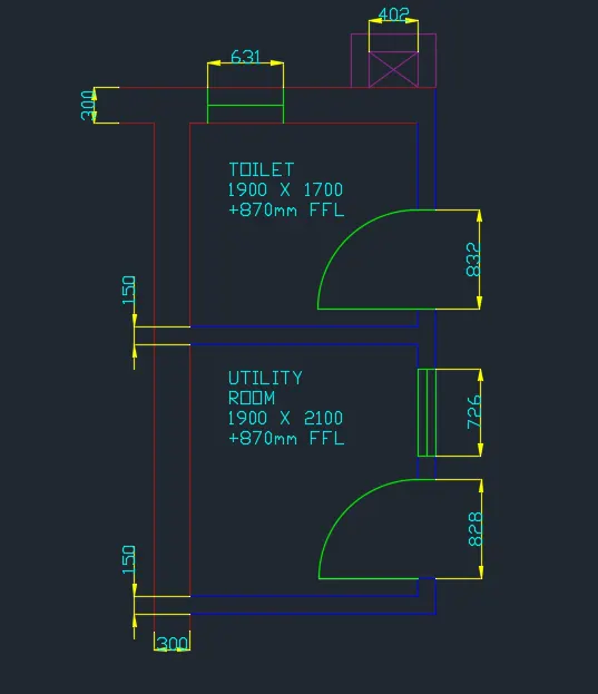
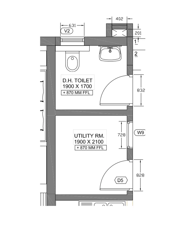
3 . Sketch the part plan for the toilers and utilities room. Consider the outer wall thickness as 300mm and inner wall thickness as 150mm. Also, assume the missing dimension, Texts, dimensions, and hatches are only for references. Also, symbols for toilets and w/c are also for references.
- AIM: To sketch the part of plan for toilet and utilities room
- INTRODUCTION:
The above plan consists of a toilet and utility room
The outer wall thickness is 300mm
Whereas the inner wall thickness is 150mm
- PROCEDURE:
Click on AutoCAD application and run the file
Type QNEW in command box
Select default settings as Imperial (Feet and Inches) and press enter
Keep ortho on
Type UN in command box for unit's settings
Select Decimal as unit type
Precisions as 0
Type limits in command box and enter 0,0 as first left corner values
And 2500,5000 as upper right corner values
Enter Z and A enter in command box for zoom all
Now draw the required length in X line and Y line respectively as shown in fig.
Offset the areas where ever it is required
Trim the unwanted lines
Leave the places for door and ventilators as per its dimension shown in fig.
Give the offsets as shown in fig.
Give the text and dimensions as per the fig.
To draw the door
Take the parallel line at the distance assumed as per wish
Take a circle and draw as per the required width
Trim the unwanted part
Then the doors of required rooms will be ready
Similarly draw for all the doors
Click on layer properties
Color can be automatically selected for required sections such as boundary line, partition walls, doors, windows, text, dimensions, etc.
Click on line type and line color to change the color and type of the required portion
Select load for required portions
It will automatically select the color given by self
Keep all the layers on
Select all the units as per layer
The plan for utility room and toilet is ready
- RESULT: