Creation of geometries by Coordinate system methods using AutoCad
- AIM:
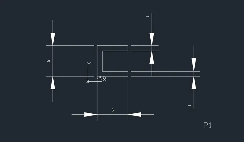
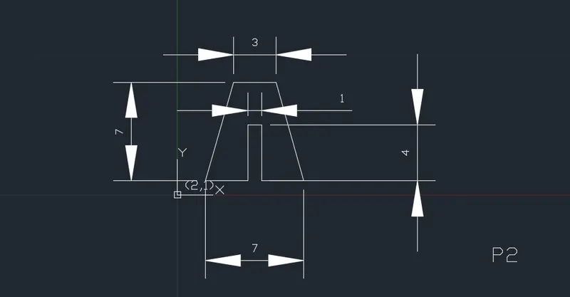
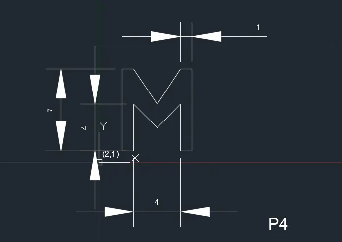
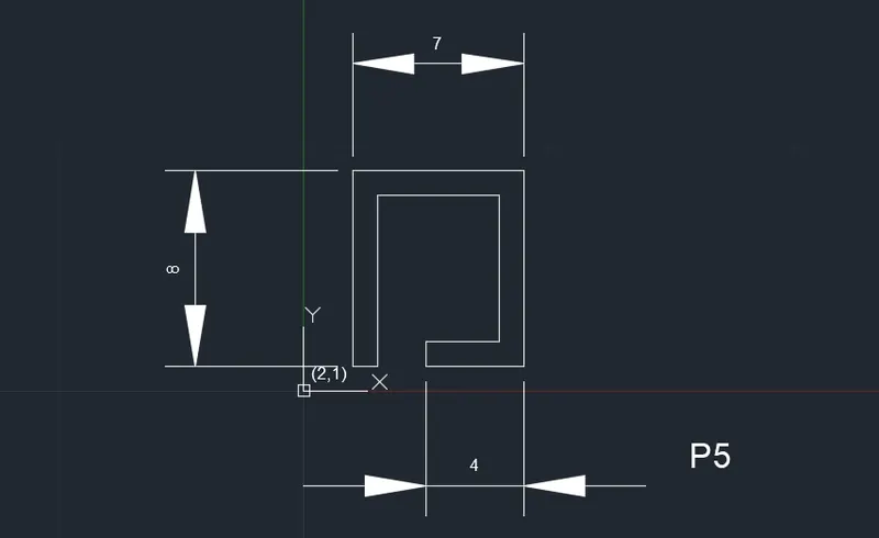
To Create the geometries for Given Diagrams using all the coordinates system methods. By using the Line tool to create the geometries.
- PROCEDURE:
There are four types of coordinates systems.
# Absolute Coordinate system
# Relative Rectangular Coordinate system
# Relative Polar Coordinates
# Direct Entry Method
STEP 1: Enter the first point, by using line command
STEP 2: Click Enter, While the line is drawn enter the next point by using any of the coordinates system
STEP 3: Draw the next point from previously drawn point by using Relative coordinate system
STEP 4: Such as for example, after first point is given and drawn, the second point is drawn with respect to X and Y
STEP 5: In command box, mention the length with @ for x axis along with length for y axis, ex: @4,0 - The line moves 4 to positive direction and y axis doesn't have a coordinate here.
STEP 6: If angle is required, use of Polar coordinate is required by typing in command box as @desiredlength<desiredangle for the creation of angle with respect with to its length
STEP 7: For example, an angle of 45degree for the length of 5 is given by using Polar coordinates such as - @5<45 in line command.
STEP 8: Direct Entry method, by using keyboard and direction along the mouse the values are provided and it is the easiest method.
- RESULTS:
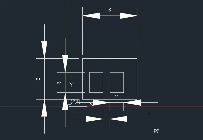
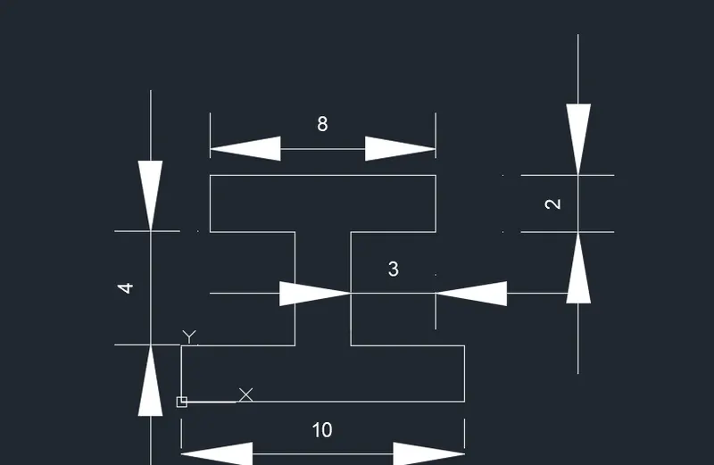
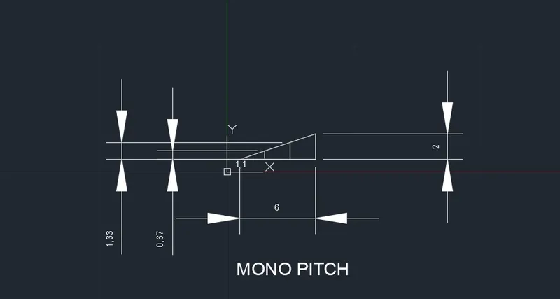
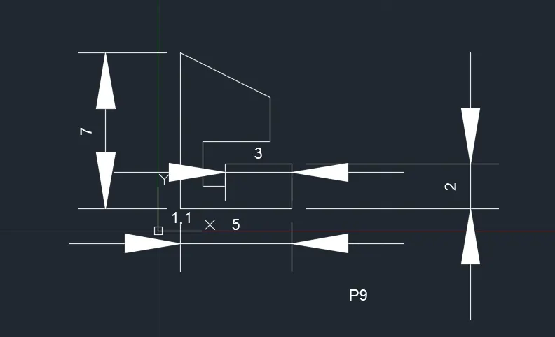
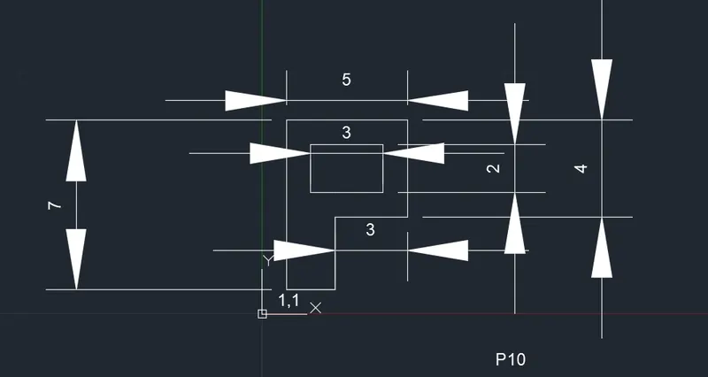
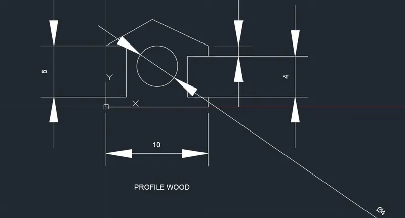
The Below given Geometrics are drawn by using AUTOCAD 2022 and diagrams are drawn by using coordinates system.