Creating Kitchen layout, Hatching of Architectural elements and sectional view of an Industrial Building in AutoCad
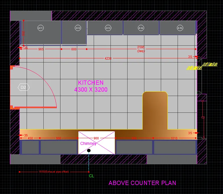
Create the layouts of the Kitchen and provide hatches pattern as shown. Also, use blocks wherever required. Provide appropriate dimensions in the plan. Assume the size of doors, appliances, and others as per the standards.
AIM:
To Create the layouts of the Kitchen and provide hatches pattern as shown
REQUIRED TOOLS:
LAYERS
XLINE
LINE
RECTANGLE
OFFSET
TRIM
CIRCLE
DIMENSIONS
TEXT
HATCH
PROCEDURE:
SETOUT THE DRAWING:
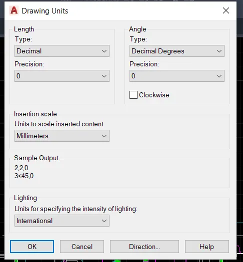
UNITS:
COMMAND: UN> Decimal >
Insertion scale > MM
LIMITS:
COMMAND: LIMMAX >
Set the maximum limits for the drawing.
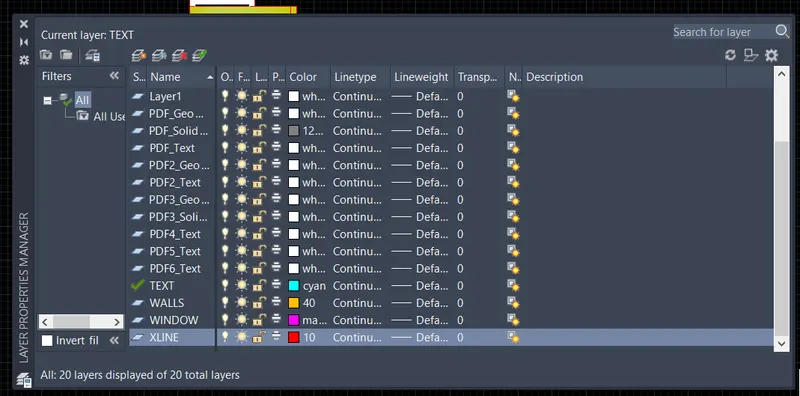
Creating New LAYERS
Invoking the Tool:
RIBBON: Layers > Layer Properties > New layer
XLINE:
Command: XL>
Creating the one Horizontal and Vertical XLINE then Offset the Xlinnes based upon the dimension of the drawing.
OFFSET:
Command: OFF>
Offset all vertical lines, the thickness of the wall 230mm and
Offset 4230mm of the internal room length and 230mm wall thickness. then
Offset all Horizontal lines, the thickness of the wall 230mm and
Offset 3130mm of the internal room length and 230mm wall thickness.
TRIM:
Trim all the extended lines around the plan.
OFFSET:
Creating the inside of the kitchen room things by using the offset command with their respective dimensions and Trimed all extended lines.
Creating the DOOR & WINDOW:
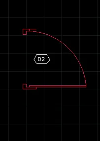
The opening of the door was taken as 1000mm and created the Frames on both sides.
BLOCK:
Command: B>
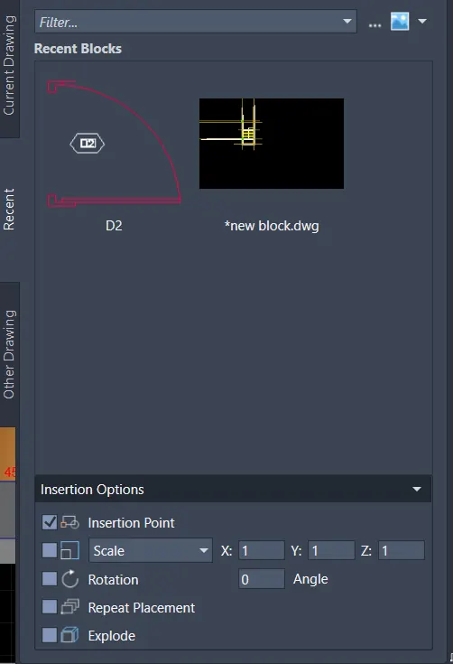
Converting the door object into the BLOCK and INSERT the block at the Door position.
INSERT:
Command: I>
DIMENSION:
Command: DIMLIN>
Plot the dimension of the room and the object inside of the kitchen.
HATCH:
CREATING THE FLOORING OF THE KITCHEN:
Command: H>
Go to the OPTION >
Select the HATCH >
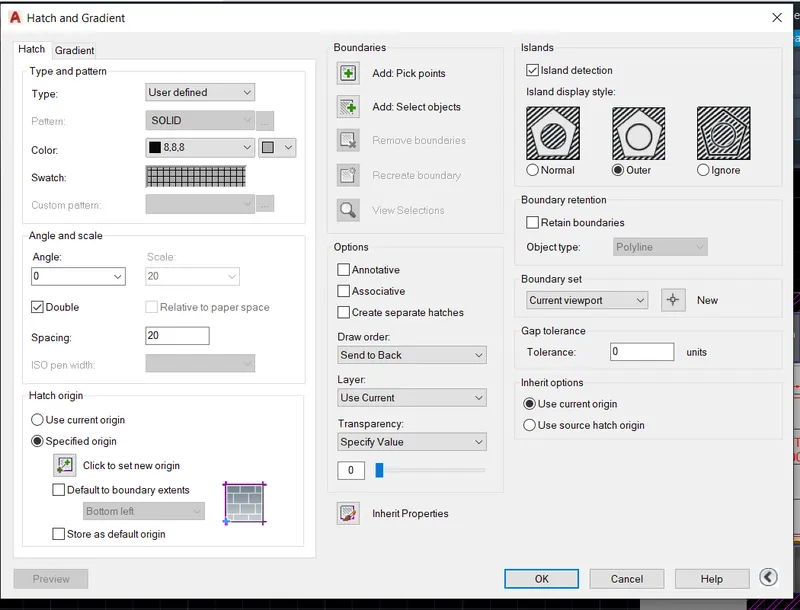
TYPE AND PATTERN:
TYPE > Select User-defined >
Color> select the colors of the line and background
Angle and scale >
select the DOUBLE (Fro the flooring as a grid pattern.)
Hatch Origin:
Select the origin of the Hatching to start the Flooring hatch. I selected the origin at the corner of the room.
Boundaries:
Select the Add pick point and select the internal point to hatcH and press the ESC button, it brings back to the Hatch and Gradient dialogue box.
Remove Boundaries:
By this option we can remove the boundaries of the dimensions and the text and the background of the text and dimension will be cover the hatch.
Option:
Select the ASSOCIATIVE For Associating the Hatch with the Boundary line.
Draw Order:
When we are hatch multiple hatches on the object, In Draw Order many options will be there for showing the hatch
Like, send back, Bring front, Do not Assign, send behind the boundary, bring in front of the boundary.
Layer:
With this layer option, we can change the layer as required of the created layers.
Transparency:
we can adjust the level of transparency of the hatch.
Islands:
Island detection
Select the island-style OUTER for ignoring the hatches inside of the boundary.
OK>
Creating the GRADIENT:
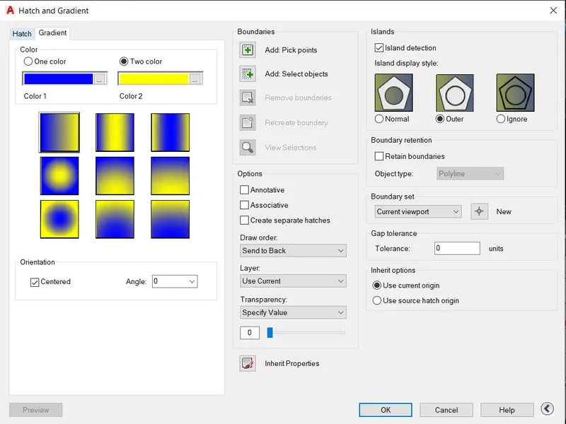
Color:
It is similar to the hatch options, the difference will the color
the hatch will come as a solid with a combination of the multi-colors.
Hatching the walls:
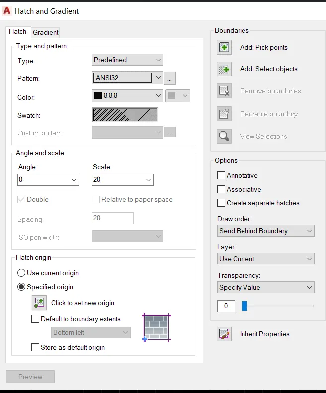
Select the hatch pattern ANSI32 for showing the BRICK work and in some places, SOLID patterns will be hatched.
Hatching to the Snacks counter:
Selected the gradient type and select the color, then pick the internal point of the Hatch area and REMOVE BOUNDARIES of the dimensions and text for the hatch will be spread entire area.
Preview the Hatch style and check the mistake anywhere on the hatch
Press OK>
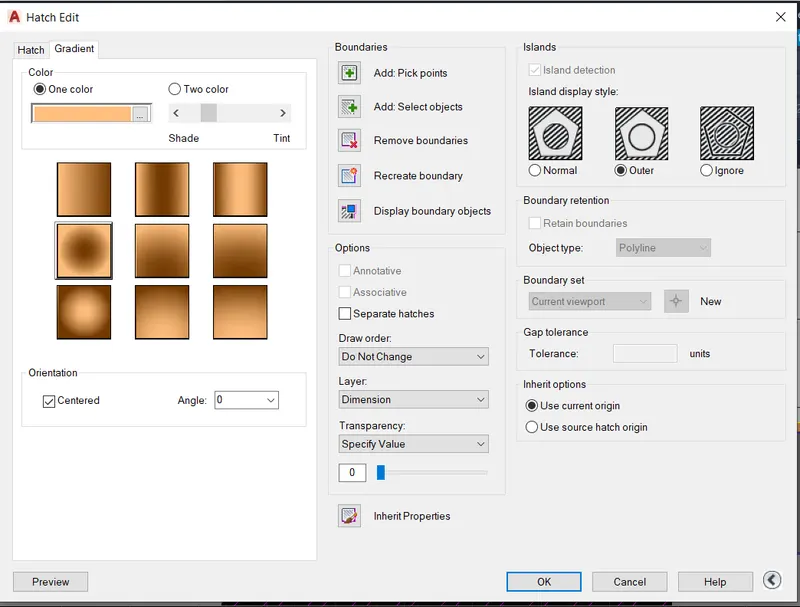
Hatching at the HOOB area
by choosing the gradient and selecting one color and adjusting the Shade and Tint
Pick the internal point of the Hatching area and Remove the Boundaries of the text and circles.
Preview the Hatch
Press OK>
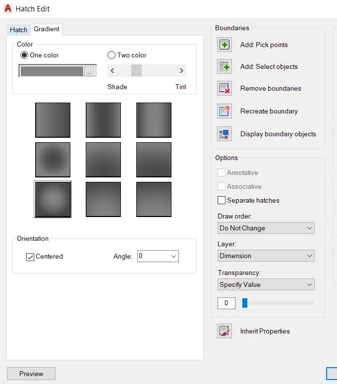
HATCHING to the Fridge:
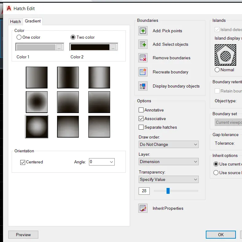
Selected the Gradient with two colors and choose the two different colors and
selected the orientation of the Hatch and pick the internal points of the hatch area
ADD: Select-Object:
By using this option we can Add more Hatching areas as to where we required them.
Invoking the tool
Select Object> Pick internal point> select the internal points of the object to hatch
Press OK>
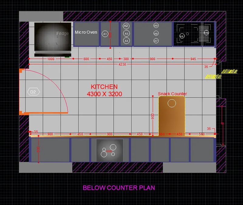
RESULT:
A similar procedure is used for sketching both Counter plans.
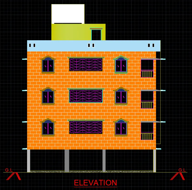
2. Create the elevation of the plan created in Challenges 7 and apply proper hatch in the walls, doors, windows, and other architectural elements. Refer to the dimensions in Plans and sections in Challenges 7.
AIM:
To Create the elevation of the plan created in Challenges 7 and apply proper hatch in the walls, doors, windows, and other architectural elements.
REQUIRED TOOLS:
LAYERS
XLINE
LINE
RECTANGLE
OFFSET
TRIM
ARC
TEXT
PROCEDURE:
XLINE:
Creating the X lines over the loan for projection of the columns, window, door, walls, etc.,
Command: XL>
Create one horizontal X line and offset the Horizontal line dimensions are referred from the section of challenge 7 plan,
OFFSET:
Command: off>
Creating the floors with a given dimension in the section-AA and creating the sill level of the window by offsetting 900 from the floor level,
TRIM:
Trimmed all extended lines over the elevation and create the proper elevation as shown in the given drawing.
Creating the Windows:
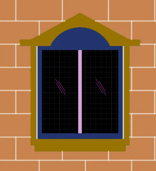
The size of the W2 window was chosen as 900x900 and the W3 window size is 1500x900
Creating the rectangle with a dimension of 900x900
Create the coping of the window by assuming the dimension,
Trim the extended lines by TRIM command, and make it as proper window model, and copy to all their respective places.
Then create W3 with a RECTANGLE command by taking the dimension of 1500x900mm and offset the panel thickness and creating the Groove of the window.
then by using the LINE command creating the bars on the window.
Creating the BALCONY
By using the LINE command created the Balcony by assuming the dimensions of the rails and jambs.
Creating the Sunshades:
The width of the sunshade is taken as 450mm and front side thickness is 75mm and the Rear side thickness is 100mm and copied to all places where the window projection is required.
HATCH:
Type and Patterns:
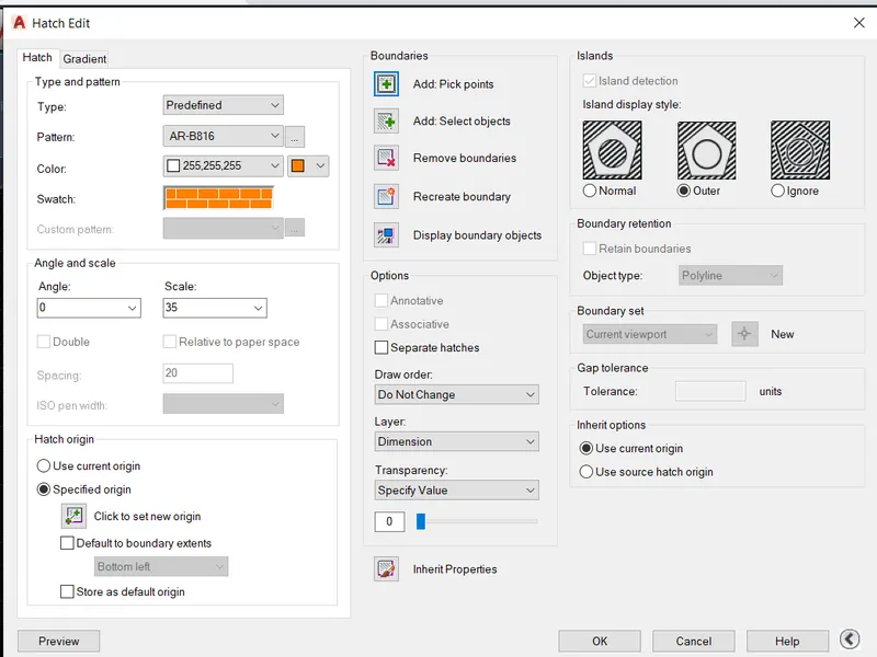
The pattern will be Selected as the AR-B816 and
Type > Selected as predefined (Already define the brick pattern in AUTOCAD)
Color > selected as the brick color
Hatch origin:
Specified origin at the corner of the wall.
Boundaries:
select the Add pick point on the wall and press ESC>
Islands: select the island display style OUTER >
PREVIEW:
Preview the hatch how it's coming and if any changes are required then press ESC> again it will bring back the Hatch Dialogue box and we change as per our requirements.
Press OK>
CREATING THE HATCH TO THE PARAPET WALL:
COMMAND: H>
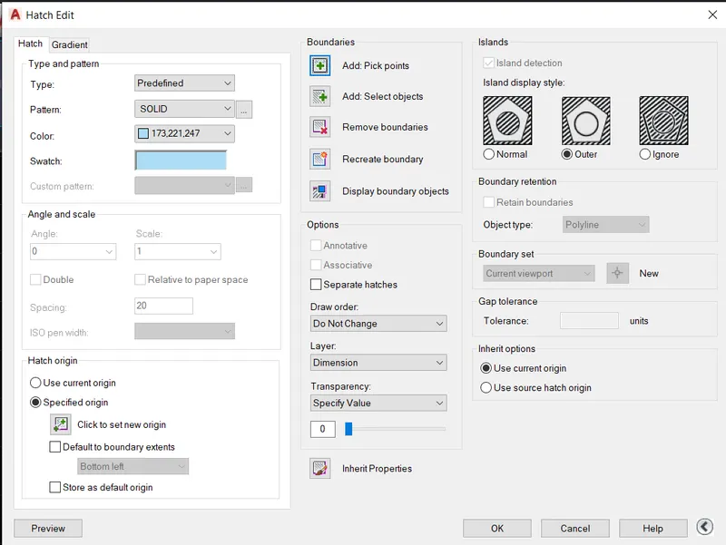
For the parapet wall select the solid pattern, and cyan color selected.
Pick the point on the drawing and press ESC.
Press OK>
CREATING THE HATCH FOR HEAD ROOM:
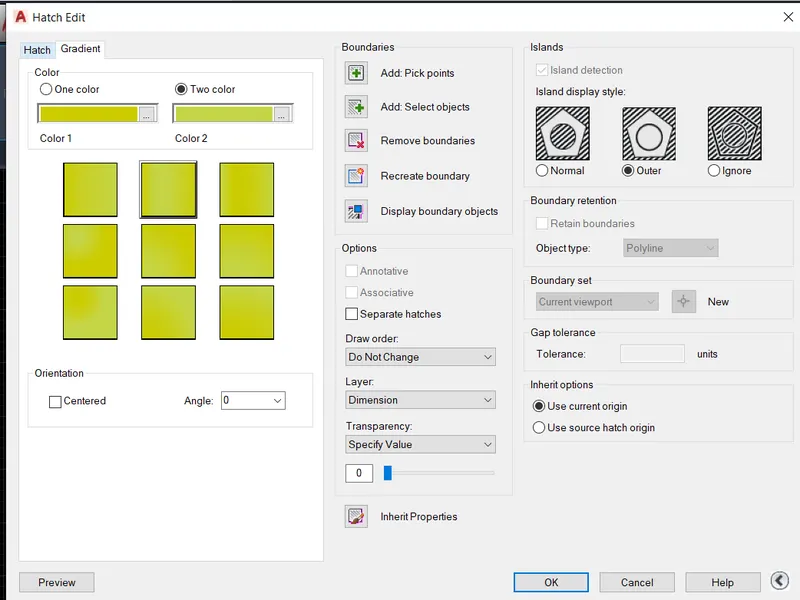
For Headroom, I choose the gradient for good looking
Select the Gradient:
The color type selected the Two-color and choose both the similar color and select the orientation of the pattern
Pick the point on the model and press ESC.
PREVIEW:
preview the hatch on the drawing for checking the appearance and press ESC>
if it's good then press OK or edit the Hatch as we required styles.
Hatching the Overhead tank:
Selected the solid pattern for the Overhead tank hatch and
pick the point of O.H.T on the drawing
PREVIEW:
Preview the hatch and press ESC>
then Press OK>
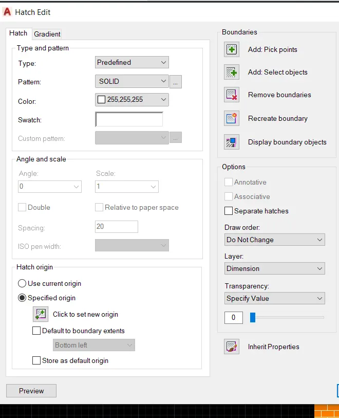
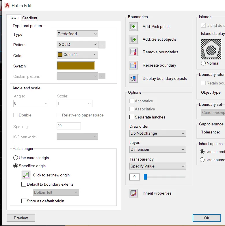
HATCHING TO THE WINDOWS:
For window hatching, The FRAME of the window hatch with solid pattern and color chosen as color -44
pick the internal point of the window frames
and Preview the hatch
then Press OK>
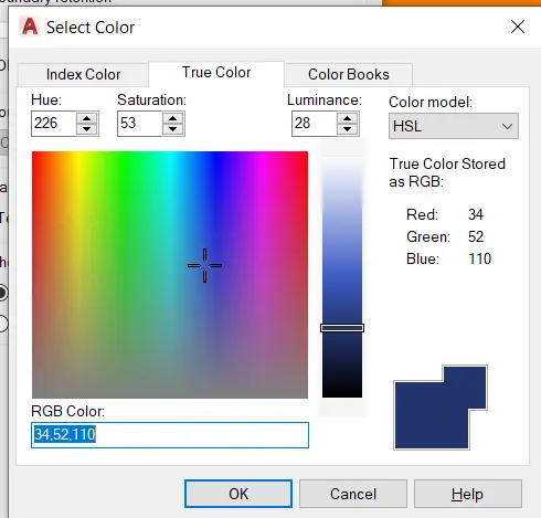
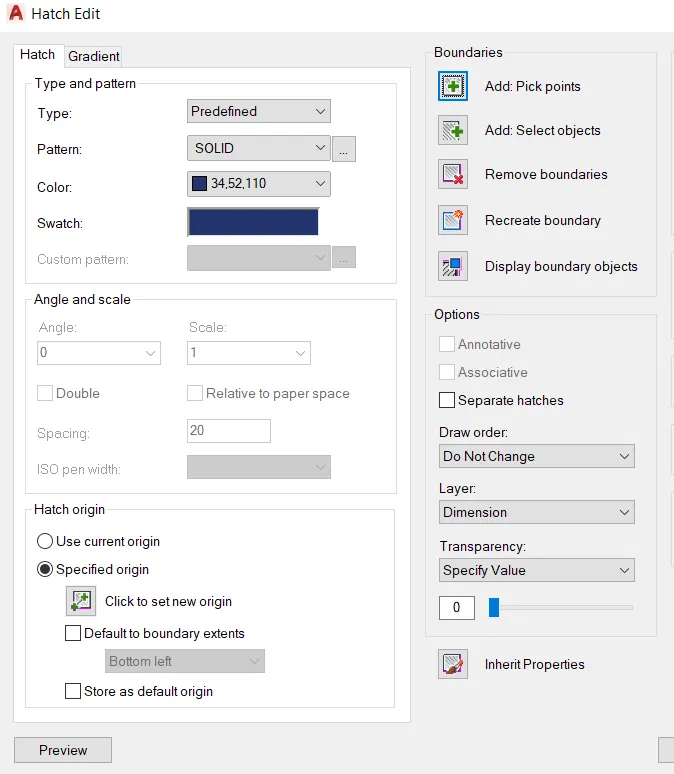
window inside hatch with solid pattern and color chosen as color -34.52 choose by select color tab
pick the internal point of the window frames
and Preview the hatch
then Press OK>
RESULT:
Sketch the ELEVATION by using various Commands and Tool.
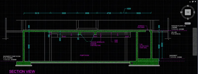
3. Create the section view of an industrial building as shown in Figure. Provide appropriate hatches and dimensions wherever required. Also, provide annotations to the drawing.
AIM:
To create the section view of an industrial building as shown in Figure. Provide appropriate hatches and dimensions
USED TOOL:
XLINE
OFFSET
TRIM
RECTANGLE
DIMENSIONS
TEXT
MULTILEADER
HATCH
PROCEDURE:
XLINE:
Creating the Horizontal and Vertical Xline.
Invoking the tool
Command: XL>
OFFSET:
Offset the height of the building 5850mm from Floor level and offset the 100mm floor thickness, then 300mm of the basement over the 100mm P.C.C, and 500mm footing over the 100mm P.C.C, and width of the footing 1000mm on both side from the column face.
Creating the centerlines of the column with given dimensions, and offset the 175mm on both sides of the centerline, and making the 350 mm width of the column.
Creating the combined footing at the filter feed tank and creating a manhole with a 750x750mm size at top of the roof.
Created the Floor beam with a depth of 300mm and 100mm thickness slab over the beam.
creating the False ceiling details as shown in the figure by taking the dimensions, and creating the DUCT portion in the False ceiling.
TRIM:
Trim all the extended lines over the section and around the section.
Invoking the tool:
COMMAND: TR>>
Dimensions:
Command: DIMLIN>
plotted the dimension of the room and thickness of the slab and showed the levels of the basement, flooring, slab.
MultiLeader:
Creating the Multi leaders at the required places for showing the details of manhole and duct.
Invoking the tool:
RIBBON: Annotate > Multileader
TEXT:
Text the Room names and other requirements by using the MText command.
Invoking the tool:
Command: MT>
HATCH:
Creating the Concreting Hatch to the beams, column, and footings
Command: H>
Pick the internal point of the hatching areas then press ENTER>
For EDITING THE HATCH:
Double click on the HATCH or right-click the mouse and select the HATCH EDIT option it brings to the HATCH EDIT dialogue box.
Change the Pattern which we required, I choose the concrete pattern for showing the concrete of the Beams, columns, Footing, and P.C.C below the flooring.
choose the color of the pattern and background.
Scale the pattern for better visibility, and Press OK
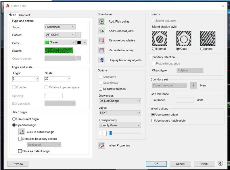
Another way also is there to hatch By directly we can use the hatch pattern a RIBBON and pick point also available to select the Hatching points, We can change the properties of the hatch like color, scale, angle, etc., Option called Hatch edit,
we can match the properties of the hatch with one hatch to another hatch by selecting the Match Properties.

Hatching the P.C.C below the Footing and Basement.
COMMAND: H>
Choose the solid pattern with a grey color for showing the concrete structure.
Select the pick point and pick the internal point of the P.C.C below the footing and basement.

RESULT:
Sketch out the section view of an industrial building by using various commands and tools,