Creating Kitchen layout, Hatching of Architectural elements and sectional view of an Industrial Building in AutoCad
QUE-1
Create the layouts of the Kitchen and provide hatches pattern as shown. Also, use blocks wherever
required. Provide appropriate dimensions in the plan. Assume the size of doors, appliances and others
as per the standards.
AIM- create kitchen layout and give hatches pattern to the layout.
COMMAND USED IN FIGURE 1:-
- line
- layer
- hatch
- offset
- trim
- dimsy
- style
- circle
- rectangular
- text
- fillet
PROSEDURE FOR KITCHEN LAYOUT :-
- first open autocad set limits and units.
- now take layer command make 5-6 layer of different component in kitchen layout give different coloure code to each layer.
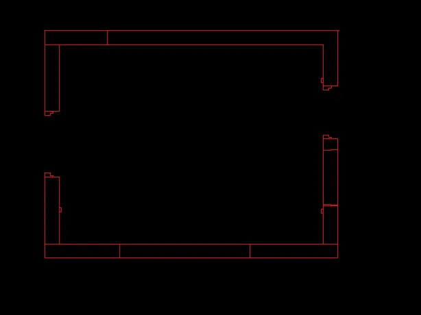
- now take line command draw outer wall of kitchen with thickness of 9 inches.
- create kitchen room of 4300x3200.
- trim unnecessary part in drawing.
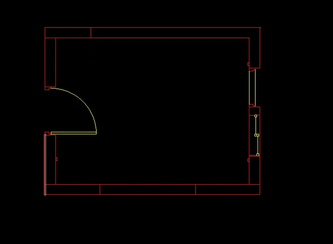
- now we have to draw window and door in the kitchen with different layer .
- assume the dimension for door.
- now with line command and offset command draw all inner kitchen assembly in the figure with different layer.
- now take text command and write all reqired text in drawing and using dimension tool give reqired dimension .
- now use hatch command give hatch where it is reqiread.
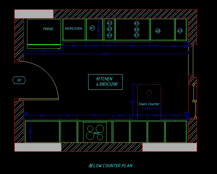
PROSEDURE FOR FIGURE 2
- for figure 2 we have to follow prosedure of figure 1.
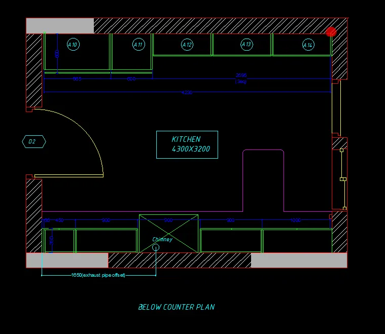
RESULT :- BOTH LAYOUT DRAWEN IN AUTOCAD.
QUE :- 2
Create the elevation of the plan created in the Challenges 7 and apply proper hatch in the walls, doors,
windows, and other architectural elements. Refer to the dimensions in Plans and sections in Challenges 7.
Refer to the elevation that needed to be created
AIM- create elevation of plan and give hatch to them
COMMAND USED IN FIGURE 2:-
- line
- layer
- hatch
- copy
- move
- offset
- trim
- dimsy
- style
- circle
- rectangular
- text
- fillet
PROSEDURE FOR ELEVATION DRAWING :-
- first open auto cad and set the liimits.
- now first we have to draw all outer lines using line command.
- assume the dimension for drawing.
- for reference insert pdf of this drawing into autocad.
- in the left side draw balcony by assuming dimension.
- in the top draw elevated water tank.
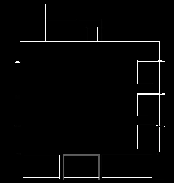
- now draw upper windows in the drawing and railings to the balcony.
- use trim command for remove unnecessary part.
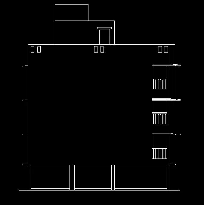
- now we have to draw inside windows and other parts into the building and give hathes to them.
- for window give hatches of glass type .
- for the wall give the hatches of solids type.
- now using text command give required text.
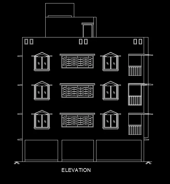
RESULT :- GIVEN DRAWING IS DRAWEN IN AUTOCAD.
QUE :- 3
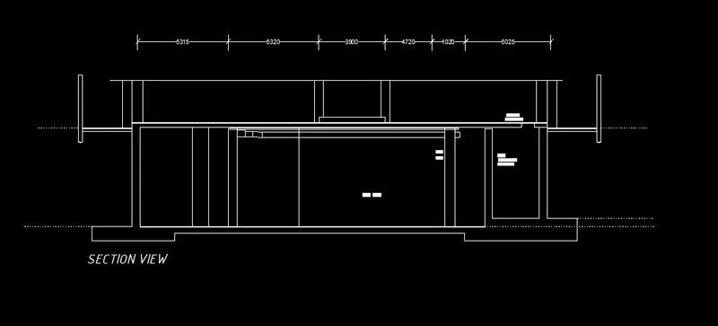
Create the section view of an industrial building as shown in Figure. Provide appropriate hatches and dimensions wherever required. Also, provide annotations to the drawing
AIM:- To create section view of an industrial building .
COMMAND USED IN FIGURE 3:-
- line
- layer
- hatch
- copy
- move
- offset
- trim
- dimsy
- style
- circle
- rectangular
- text
- fillet
PROSEDURE FOR DRAWING :-
- first open auto cad and set the liimits.
- now take line command draw all outer line as given dimension.
- using offset command give proper offset to the outer wall.
- for any reference import pdf file to the autocad .
- using text command give text where reqired.
- using hatch command give hatches where required.
 .
.