Creating Kitchen layout, Hatching of Architectural elements and sectional view of an Industrial Building in AutoCad
1) AIM :Draw a kitchen layout
Introduction : we create kitchen layout in AUTOCAD . we provide screenshots of every steps.we are using decimal,architectural and engineering units as required in plan. we use proper layers to show the dimension and text of elements. use wall thickness 230mm and door and window size are assumed.
Procedure :
- first choose units and limits before creating any figure.
-
for units, Type command - "UN"
for limits, Type command - "LIM"
- First create below counter plan and we use line,fillet,offset command. set the dimension size using 'D' command and use door or window block used previously.
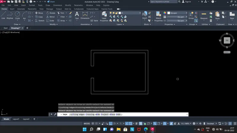
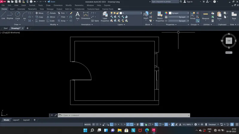
- for section part we use hatching and design center is used to get some default kitchen blocks such as refrigerator, wash basing etc.
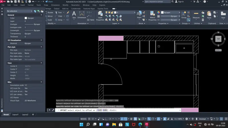
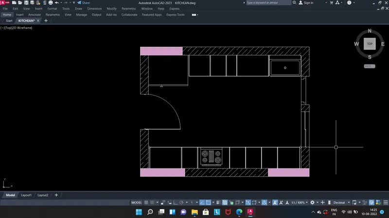
- now copy this lower counter plan and paste it and make some changes as per drawing
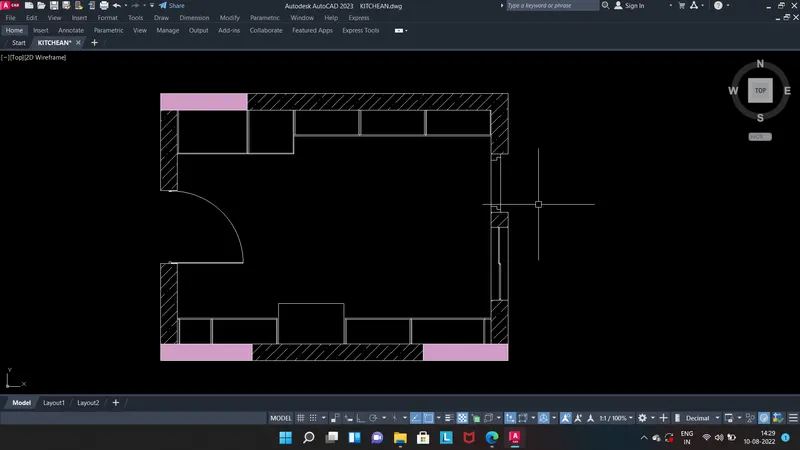
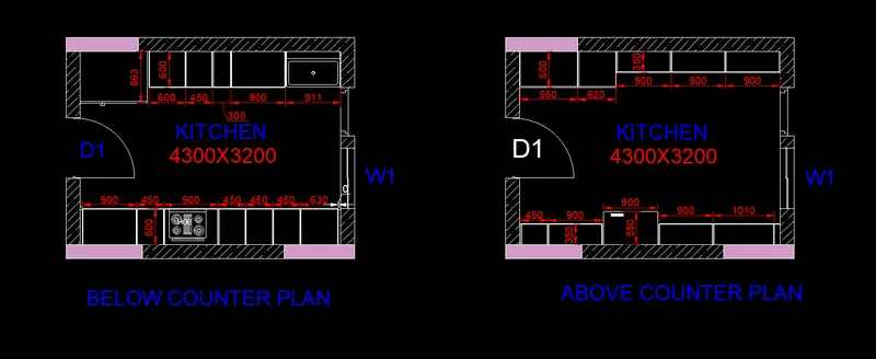
- now dimensioning the both plan and layer on of the both text and dimension:
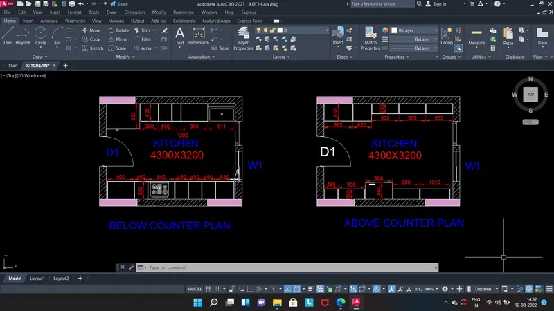
FINAL RESULT :
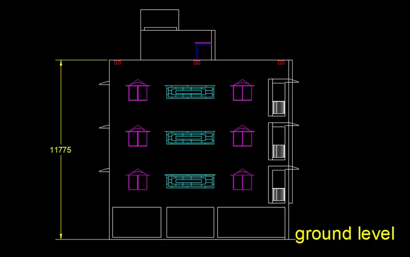
2) AIM : Create the elevation of the plan.
INTRODUCTION : Create the elevation of the plan created in the Challenges 7 and apply proper hatch in the walls, doors, windows, and other architectural elements. Refer to the dimensions in Plans and sections in Challenges 7.
PROCEDURE:
- type x line in front of plan to get the width of the building and position and dimension of windows and balcony of building.
- using the section of building ,we get the height of building and position of floor and head room.
- using section and plan, first create the boundary of elevation
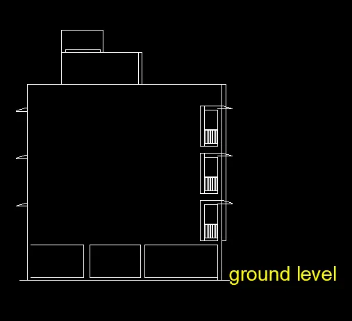
- now start creating windows in building.
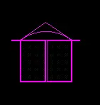
- now place this window in the building.
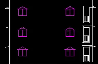
- now start creating balcony with grillls. For that use simple tool line,offset and trim.
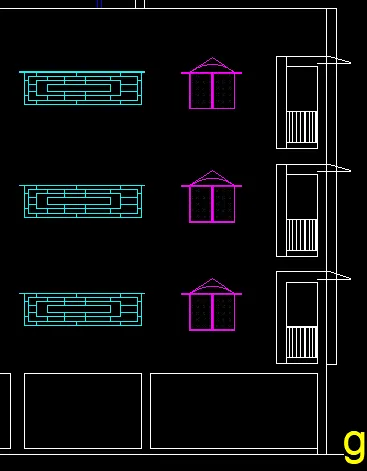
RESULT: Final front elevation of week 7 challange.
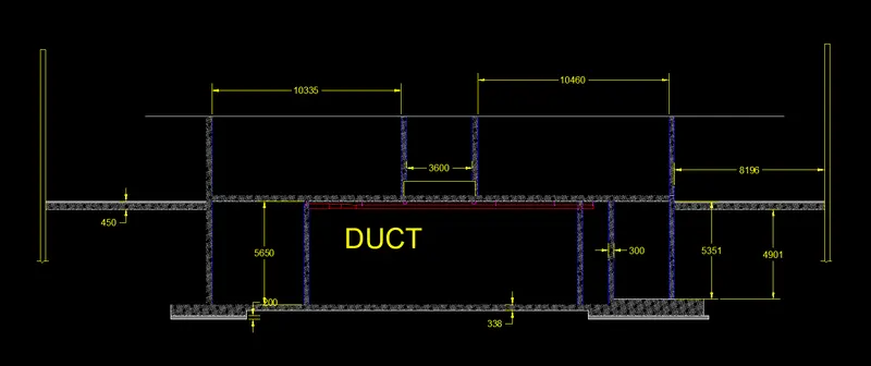
3) AIM : Create the section view of an industrial building as shown in Figure.
INTRODUCTION: Draw the section view and Provide appropriate hatches and dimensions wherever required. Also, provide annotations to the drawing.
PROCEDURE :
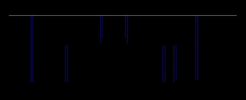
- first create grid for references as shown in the figure.
- draw the column as per given references.
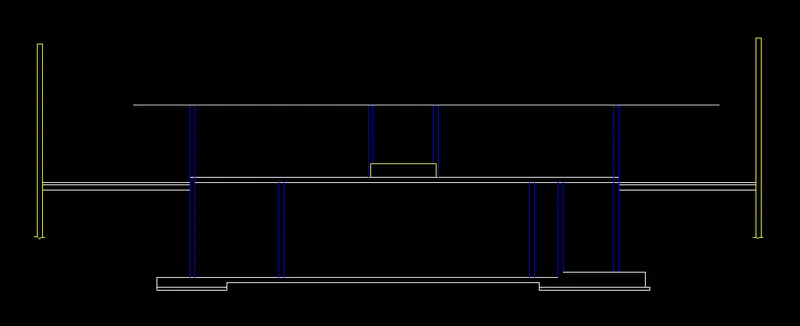
- after that create the floor and basement floor as per given in dimension and some dimension is assumed.
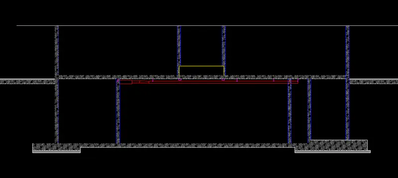
- now creating HVAC unit in this section.

- now hatching the area as per needed.
RESULT :
THANK YOU.