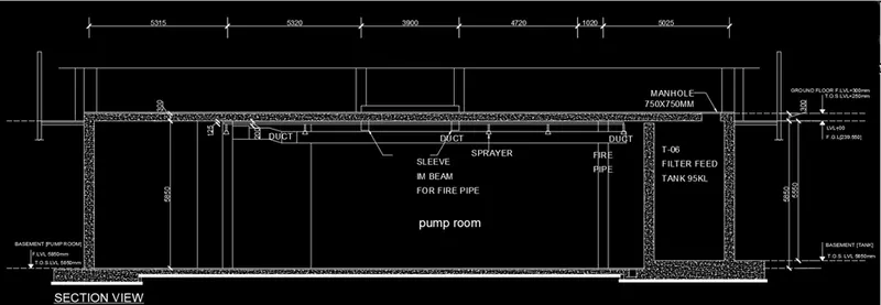
Creating Kitchen layout, Hatching of Architectural elements and sectional view of an Industrial Building in AutoCad
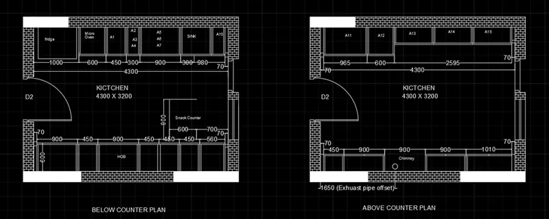
Create the layouts of the Kitchen and provide hatches pattern as shown. Also, use blocks wherever required. Provide appropriate dimensions in the plan. Assume the size of doors, appliances and others as per the standards.
AIM:
To create the layout of kitchen by using the drafting tools in AutoCAD.
PROCEDURE:
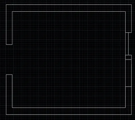
Step-1:
- First, we sketch the layout of kitchen.
- Select the command LINE and draw the outer line of kitchen.
- Use the command OFFSET to sketch the parallel lines for outer lines.
- Use command TRIM to eliminate the unwanted lines.
STEP-2:
- After completing the outer layer, we should draw the furniture area.
- Select the command LINE and draw the interior space for required dimensions.
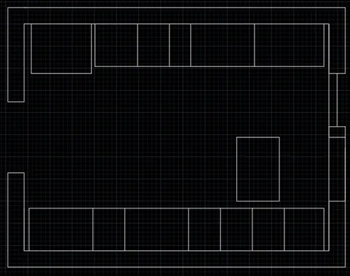
- Use the command OFFSET to sketch the parallel lines.
- Select the command CIRCLE to sketch the door.
- Use command TRIM to eliminate the unwanted lines.
- Then use the command HATCH and select the pattern BRICK, SOLID for highlight the sketch.
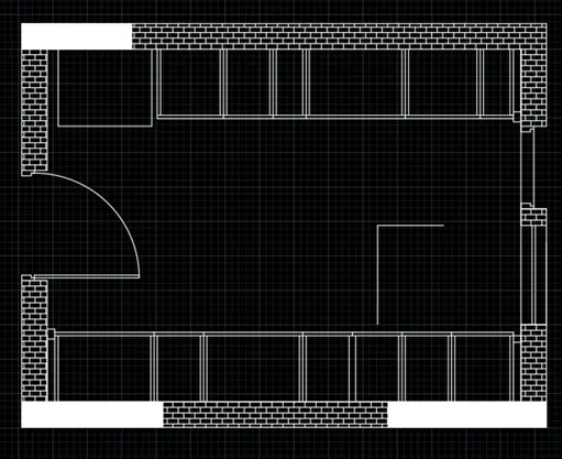
STEP-3:
- After completing the drawing, we should mention the dimensions and labelling fo sketch.
- Select the command DTEXT and write the required text.
- Use command DIMLIN to specify the dimensions by using the options Continue and Baseline for required dimensional specifications.
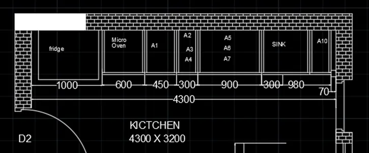
- Follow the same process for above counter plan.
RESULT:
Create the elevation of the plan created in the Challenges 7 and apply proper hatch in the walls, doors, windows, and other architectural elements. Refer to the dimensions in Plans and sections in Challenges 7.
AIM:
To create the elevation of the plan by using the tools in AutoCAD.
INTRODUCTION:
ELEVATION:
Elevation drawings are a specific type of drawing architects use to illustrate a building or portion of a building. An elevation is drawn from a vertical plane looking straight on to a building façade or interior surface. This is as if you directly in front of a building and looked straight at it.
Elevations are a common design drawing and technical architectural or engineering convention for graphic representation of architecture. Elevation drawings are orthographic projections means they are not drawn in perspective and there is no foreshortening.
PROCEDURE:
Step-1:
- Sketching elevation of a building is takes place after the completing the plan of building.
- To draw the elevation, we should extend the vertical lines from the plan by using the command XLINE at every corner, columns, windows and doors.
- using the command XLINE draw the horizontal line.
- Select the command OFFSET and draw the parallel lines for the mentioned horizontal line for plinth level, sill level, lintel level, slab level, parapet wall level etc.
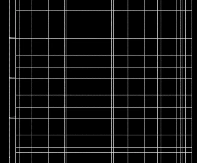
- Use the command TRIM to eliminate the unwanted lines to show the sketch of windows, doors, columns etc.
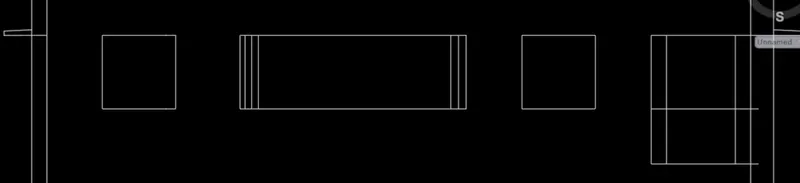
STEP-2:
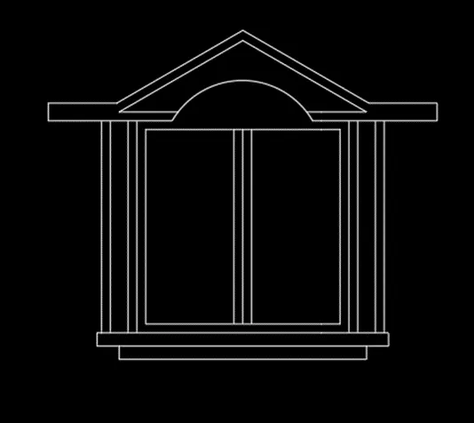
- After completing the outer sketch of windows, balcony etc, we should draw the remaining parts of the building.
- Select the command OFFSET to draw the parallel lines to sketch the window.
- Use the command ARC to draw the arc for window architecture.
- Use the command LINE for draw the lines and joining the lines for completing the sketch of window architecture.
- Use the command TRIM to eliminate the unwanted lines.
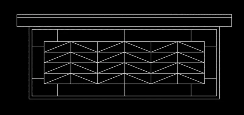
- After completing the sketch of window now we have to sketch of veranda.
- Select the command OFFSET to draw the parallel lines in vertical and horizontal direction.
- Use the command LINE for extending the lines and for joining the lines for complete the sketch of veranda.
- Use the command TRIM to eliminate the unwanted lines.
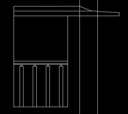
- To draw the sketch of balcony, we have to use the command LINE to draw the sketch of balcony.
- Use the command OFFSET to draw the parallel lines.
- Use the command TRIM to eliminate the unwanted lines.
Step-3:
- The completed sketches of window, veranda and balcony now we have to copy the sketches in other floors at specified places.
- Select the command COPY to copy the sketches in different places.
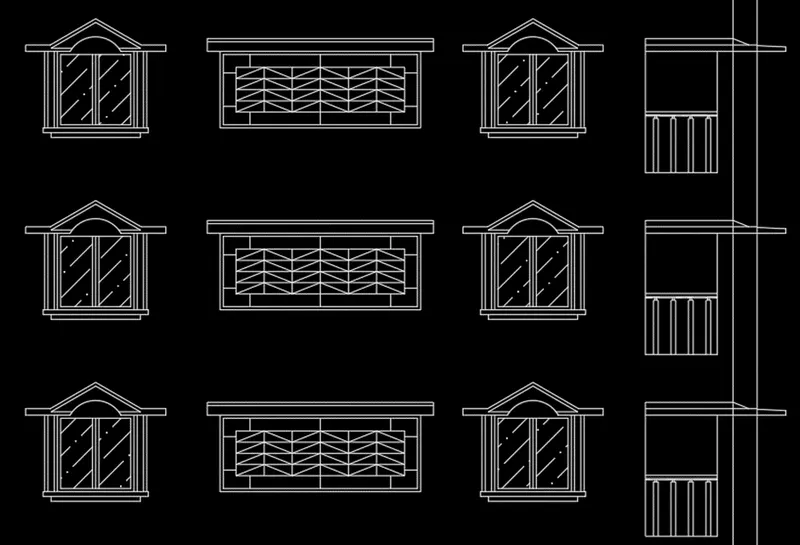
- After completing the sketch, now we have to hatch the sketch.
- Select the command HATCH and use the pattern BRICK for brick work and pattern ANSI36 for highlighting glass.
- Use command HATCH and pattern SOLID for highlighting the projections.
- Select the command GRADIENT to give colours for the building.
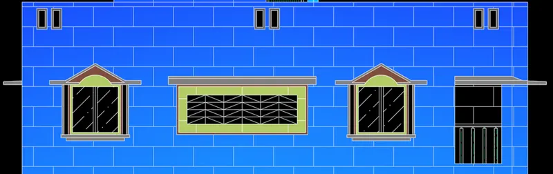
- Continue the same procedure for entire sketch.
RESULT:
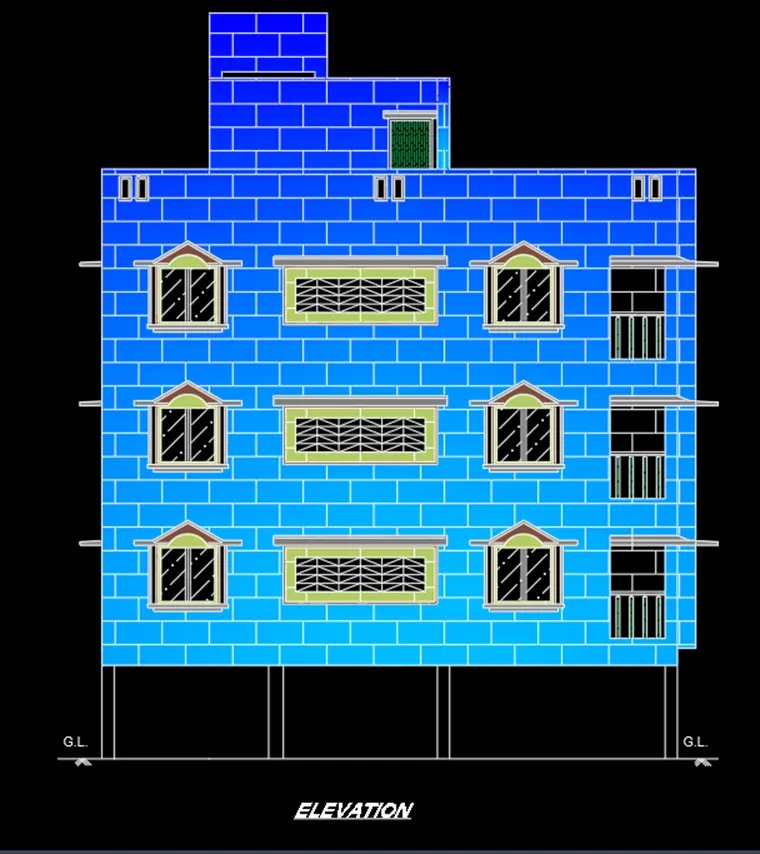
Create the section view of an industrial building as shown in Figure. Provide appropriate hatches and dimensions wherever required. Also, provide annotations to the drawing.
AIM:
To create the sectional view of an industrial building by using the tools in AutoCAD.
INTRODUCTION:
SECTION:
Section drawings are a specific type of drawing architects use to illustrate a building or portion of a building. A section is drawn from a vertical plane slicing through a building this is as if you cut through a space vertically and stood directly in front looking straight at it.
Sections are common design drawing and technical architectural or engineering convention for graphic representation of architecture. Section drawing are orthographic projections means they are not drawn in perspective and there is no foreshortening.
PROCEDURE:
Step-1:
- To draw the sketch of section of the industrial building, first we have to draw the left side sketch by using the command
- Then use the command OFFSET to draw the parallel lines in horizontal and vertical direction.
- Use the command EXTAND for joining the lines.
- Use the command TRIM to eliminate the unwanted lines.
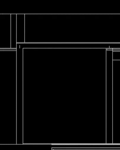
- After completing the sketch of left portion of industrial building, now we have to draw the middle portion.
- Select the command LINE to draw the lines as per the required dimensions.
- Use the command OFFSET to draw the parallel lines in horizontal and vertical.
- Use the command EXTAND for joining the lines.
- Use the command TRIM to eliminate the unwanted lines.
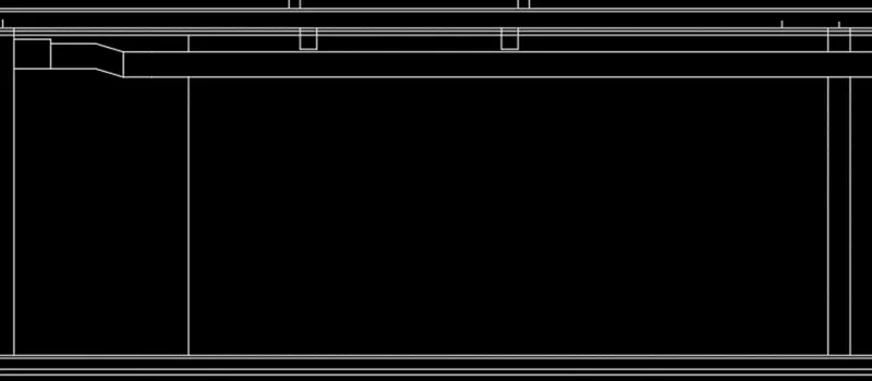
- After completing the sketch of middle portion of industrial building, now we have to draw the right portion.
- Select the command LINE to draw the lines as per the required dimensions.
- Use the command OFFSET to draw the parallel lines in horizontal and vertical.
- Use the command EXTAND for joining the lines.
- Use the command TRIM to eliminate the unwanted lines.

Step-2:
- After completing the sketch of section of industrial building, now we have to hatch and annotate the sketch.
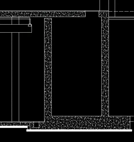
- Select the command HATCH and pattern AR-CONC for highlighting the concrete part and use the pattern SOLID in required places.
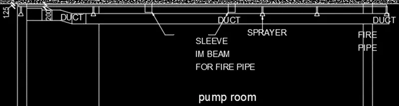
- After complete the hatching, now we have to label the sketch by using the command DTEXT, label the sketch at required places.
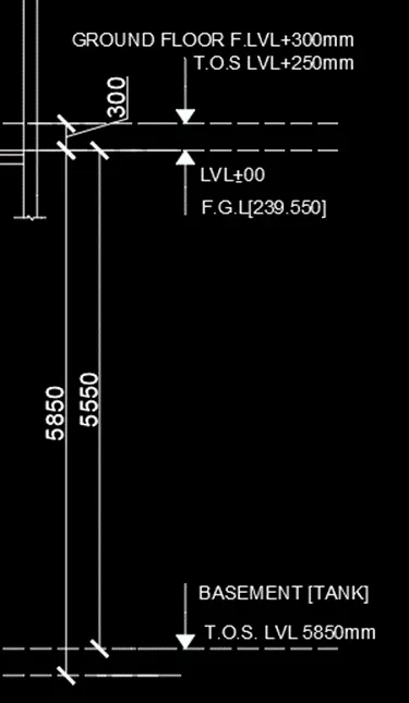
- After complete the labelling, now we have to give the dimensions for the sketch.
- Select the command DIMLIN to gave the dimensions for the sketch.
- Use the command LEADER to point the specific places.
- Continue the same procedure for entire sketch.
RESULT: