Creating Kitchen layout, Hatching of Architectural elements and sectional view of an Industrial Building in AutoCad
Aim 1 :
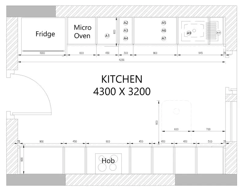
Create the layouts of the Kitchen and provide hatches pattern as shown.
Introduction:
Create the layouts of the Kitchen and provide hatches pattern as shown. Also, use blocks wherever required. Provide appropriate dimensions in the plan. Assume the size of doors, appliances and others as per the standards.
Procedure :
- Use Commands:
- Line
- Fillet
- Offset
- Trim
- Dim
- Mtext
- Hatch
- leader
- Steps:
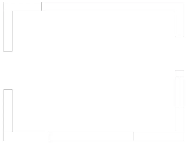
- Using all command first Draw the Kitchen plan.
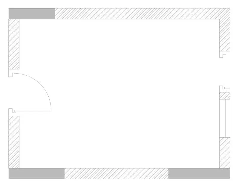
- Hatch the wall & draw the door as given.
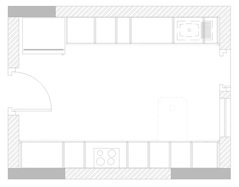
- Now draw Below counter plan furniture layout of the kitchen.
- Dimensioning the kitchen as given and annotating the text required.
- Using all command first Draw the Kitchen plan.
- Hatch the wall & draw the door as given.
- Now draw Above counter plan furniture layout of the kitchen.
- Dimensioning the kitchen as given and annotating the text required.
- Using all command first Draw the Kitchen plan.
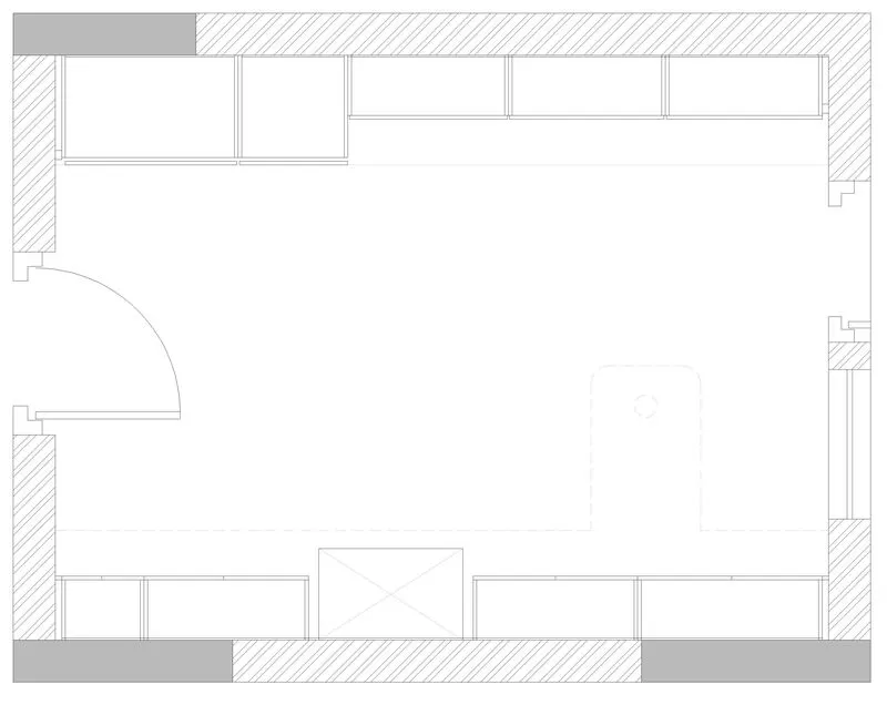
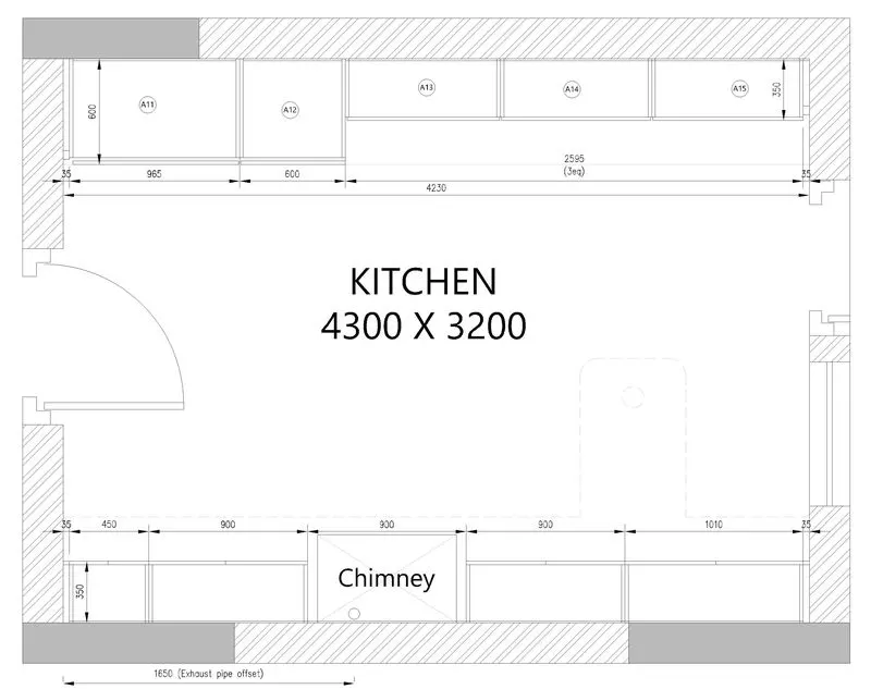
Result:
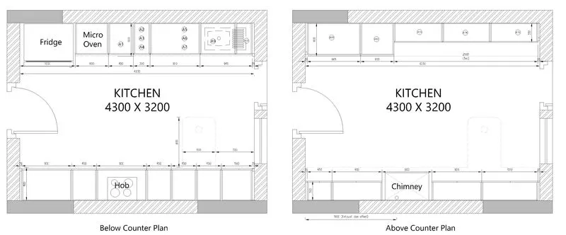
Aim 2 :
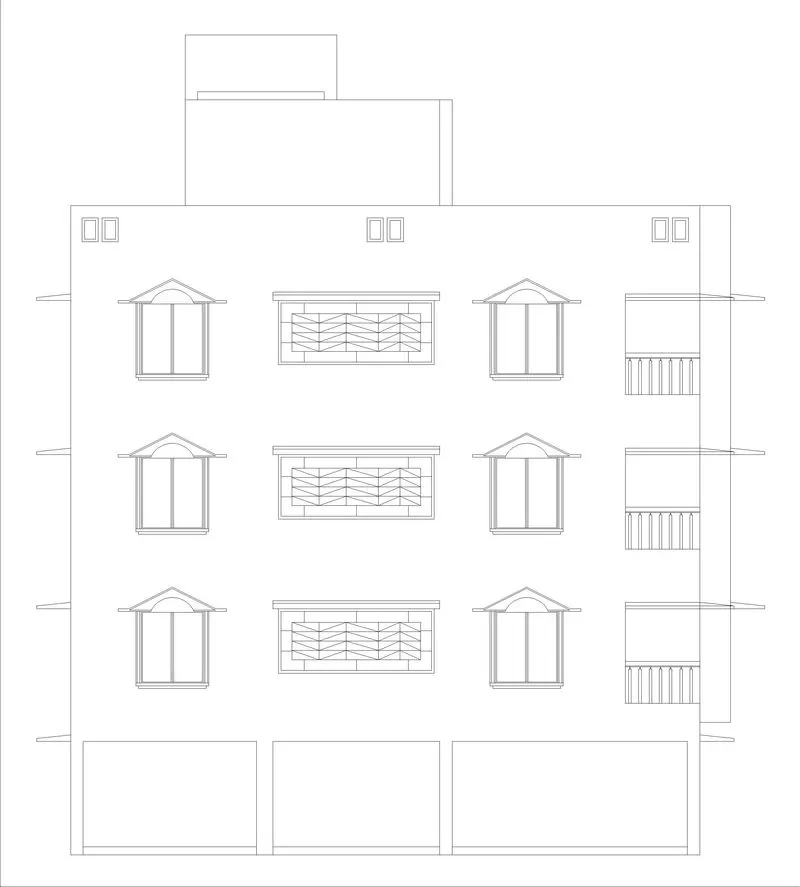
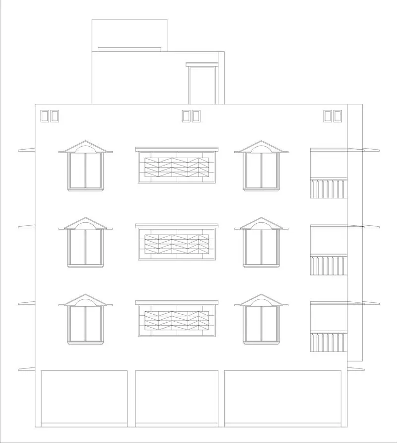
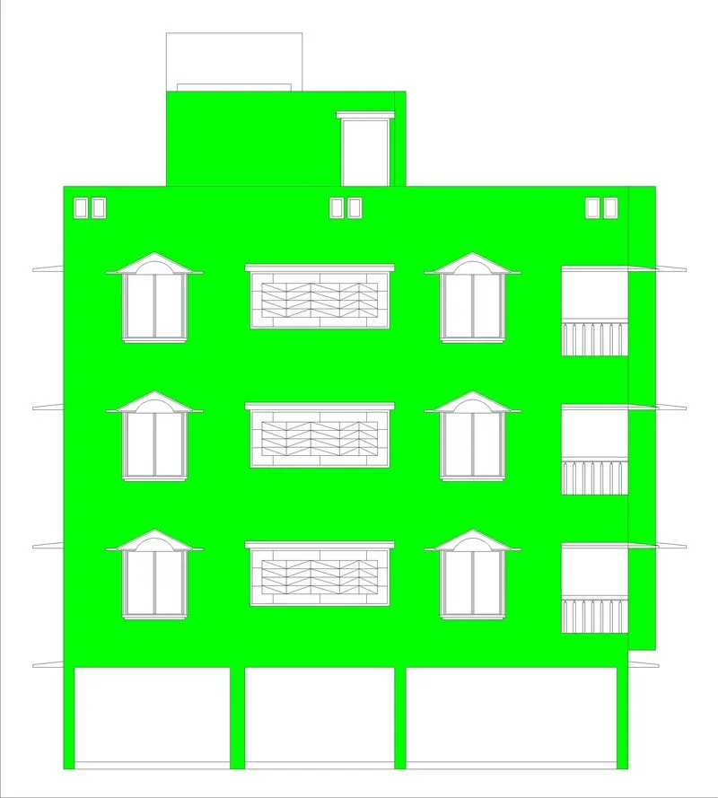
Create the elevation of the plan.
Introduction:
Create the elevation of the plan created in the Challenges 7 and apply proper hatch in the walls, doors, windows, and other architectural elements. Refer to the dimensions in Plans and sections in Challenges 7.
Procedure :
- Use Commands:
- Line
- Fillet
- Offset
- Trim
- Dim
- Hatch
- Arc
- Rectangle
- Array
- move
- Copy
- Steps:
- Using line draw the Ground Level.
- Now draw the elevation outline.
- Now draw the side shades of the windows in the elevation.
- Draw the front Balcony Elevation.
- Draw the Balcony and Window elevation of the building.
- Draw the Parapet wall elevation.
- Draw the terrace elevation top building structure.
- Now draw the top elevation door.
- Now using hatch command hatch the wall area.
- Now hatch the Corner balcony and side shades of the elevation.
- now hatch the Corner balcony railing.
- Now hatch the Front Balcony Gril.
- Now hatch the top Building structure Door Elevation.
- Now hatch the windows.
- Hatch the Parapet wall elevation.
- Hatch the top Structure (Tank).
- Using line draw the Ground Level.

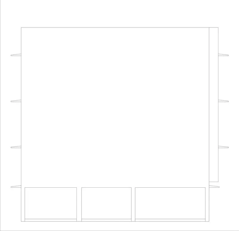
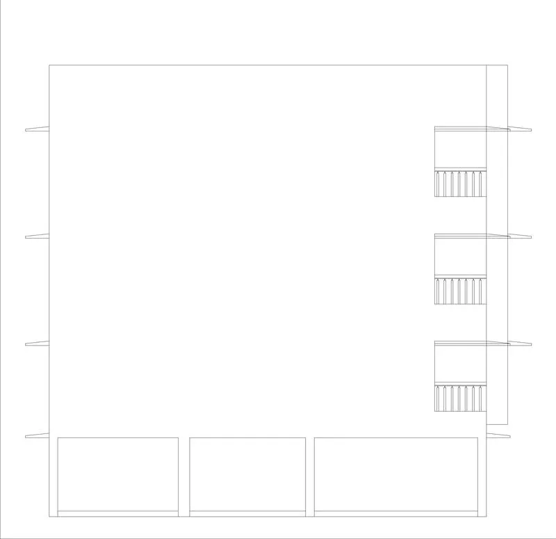
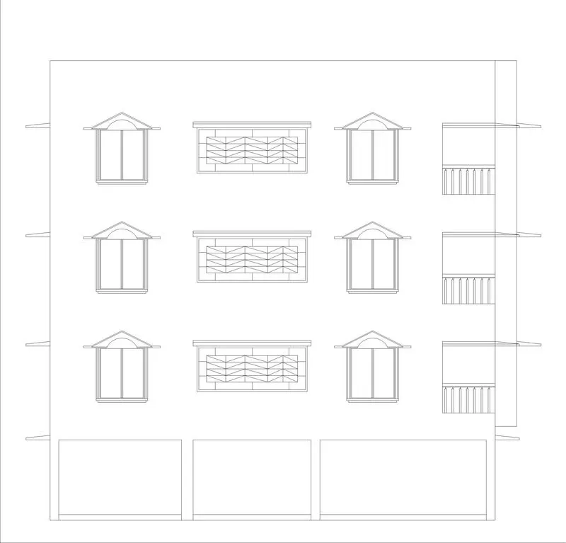
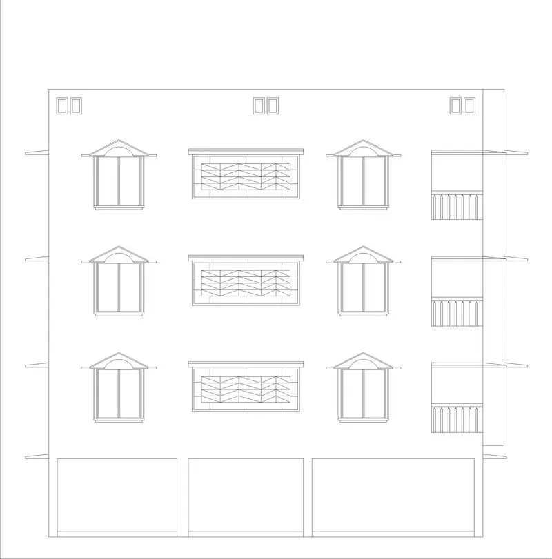
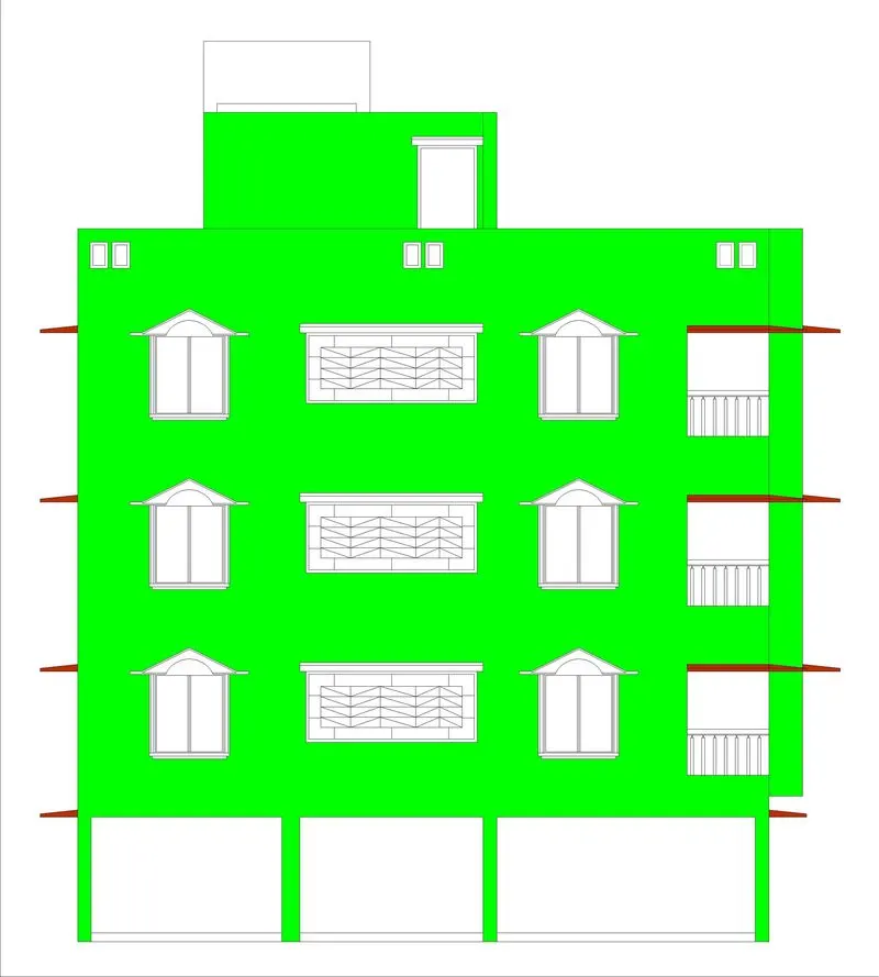
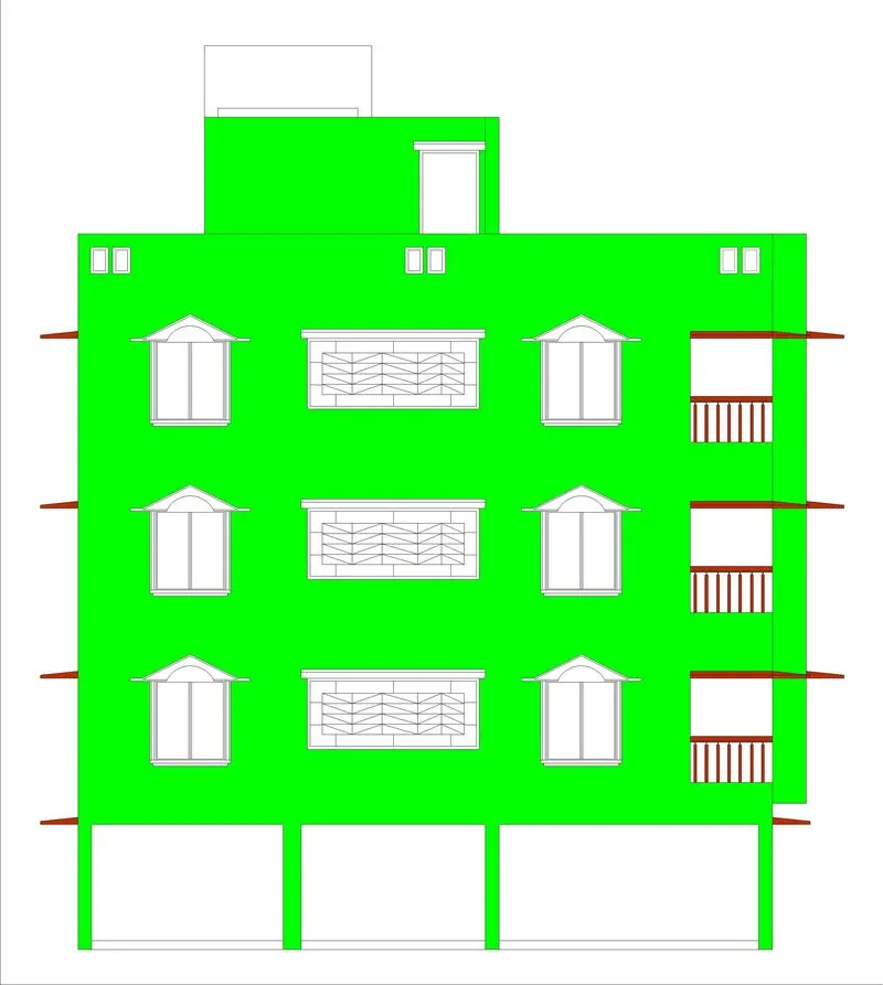
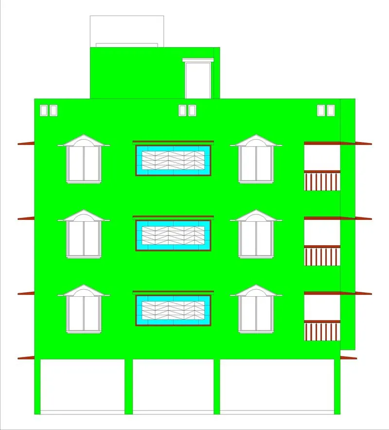
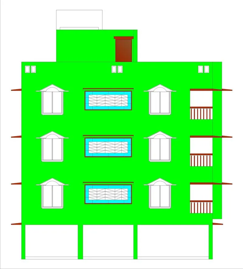
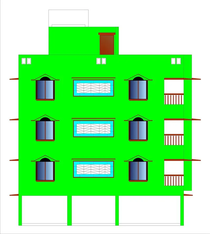
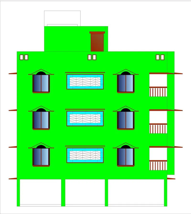
Final Result:
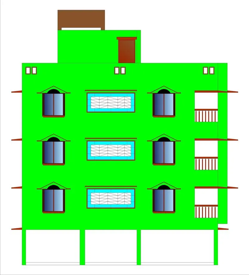
Aim 3 :
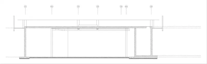
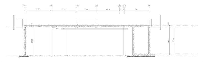
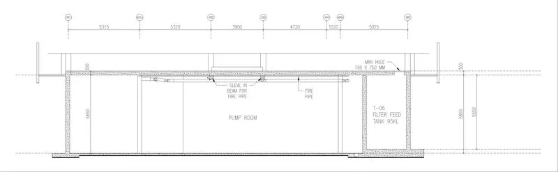
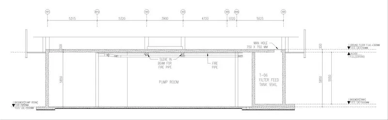
Create the section view of an industrial building as shown in Figure.
Introduction:
Provide appropriate hatches and dimensions wherever required. Also, provide annotations to the drawing.
Procedure :
- Use Commands:
- Line
- Fillet
- Offset
- Trim
- Dim
- Hatch
- Leader
- Array
- move
- Copy
- Mtext
- Steps:
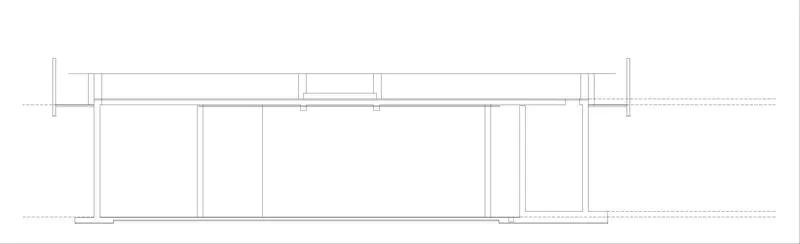
- Draw the different levels as per the given figure.
- Now draw the structure given in the figure. on the levels.
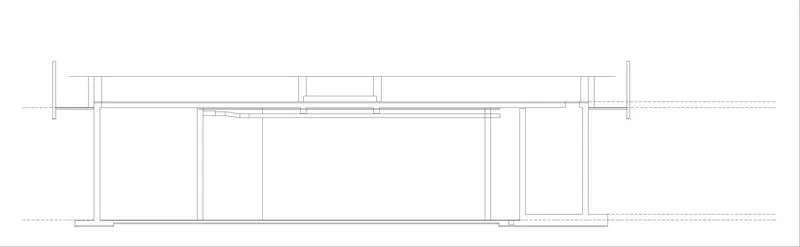
- Now draw the fire pipe as given in the figure.
- Now draw the Duct as given.
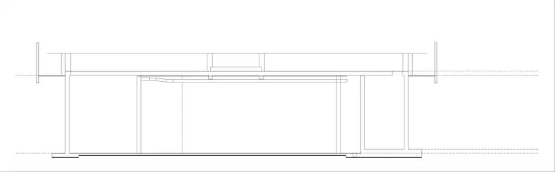
- Now solid hatch the bottom of the structure.
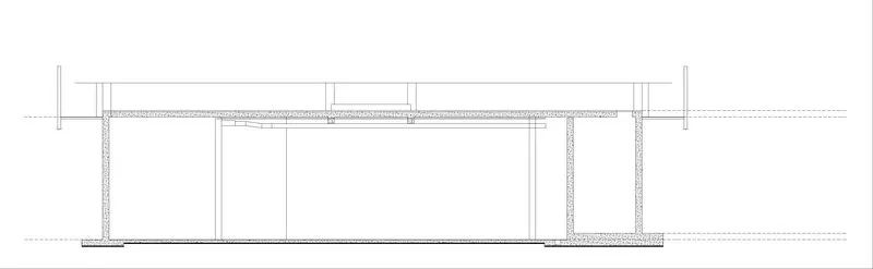
- Now hatch the Structure as area provided in the given figure.
- Now draw the Vertical reference grids as given.
- Now Dimension all the lengths as per the given figure.
- Now annotate all the leaders & Text as mentioned in the figure.
- Now annotate all the levels references.
- Draw the different levels as per the given figure.
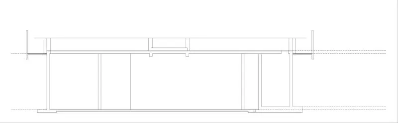
Final Result:
**All the Aims has been drawn successfully and completely**