Creating Kitchen layout, Hatching of Architectural elements and sectional view of an Industrial Building in AutoCad
AIM:- To Create the layouts of the Kitchen and provide hatches pattern as shown. Also, use blocks wherever required. Provide appropriate dimensions in the plan. Assume the size of doors, appliances and others as per the standards.

INTRODUCTION:-
To draw the Plan and Sections according to the provided Figures, I have used several autocad commands like- line,circle, rectangle, extend , offset, trim,erase,hatch, block, etc., and I set dimension (Decimal) and select milimeter in Autocad. Moreover, I set limits with command "Limits", specify the left corner points ans right corner points and then enter zoom all("z-a") in this drawing. Also, I used dimesion command for measuing the dimensions in Autocad along with text command to write drawing name. Apart from that, I have assumed several data for drawing this sketch.
PROCEDURE:-
Open Autocad and type a command "Unit" and press enter, then set unit as Decimal and set angle in degree- base angle is east -mark angle direction as anticlockwise. Type a command "DIMSTYLE" and press enter, then click to modify and go to primary unit tab and set it Decimal and set the precision to 0.0 and cick ok.
DRAWING PROCEDURE FOR LAYOUT OF KITCHEN:-
Import kitchen drawing from project-6.
- Cover blocks (Hobs and Chimney) using block.
- Provide hatch in walls and windows as per your own conception and given sketch.
- Insert Chimney and hobs in drawing.
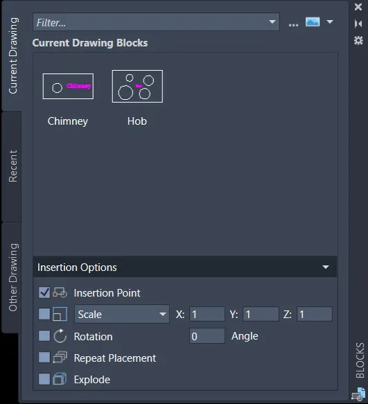
a. Take different views for the layout in model space
1. Open the drawing , use command "VIEW" to create new views.
2. The view manager dialogue box apperas .click on model , click on new to craete new view.
3. Another dilaogue box of new view appears , give the view name as "above counter plan" select the boundary as define window, and eelct it using the window selection from the drawing.
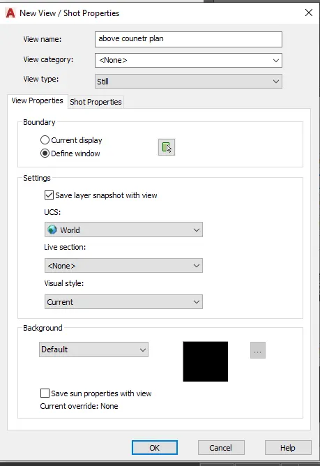
4. Click on OK and the view with name above counter plan and the selected drawing will be created.
5. Similary craete views for below counter plan, hob , and A11 to A14 cabinets.
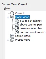
b. Create the layout with four viewports, with A4 sheet.
6. Open the layout tab, rename the layout as kitchen layout.
7. Delete the exisiting viewport
8. Default is the A4 sheet.
9. With "MV" command create 4 viewports by making the window .
10. Type command "VIEW" in the layout tab , select the required view and click on the viewport where it has to be displayed and lock each viewport.
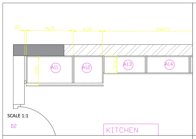
11. Select the A11 to A14 cabinet view in the first viewport,zoom and pan to fit in the viewport
12. Go to paper space ,with Text command type SCALE 1:1
13. Enter command "MS" click on the second viewport .
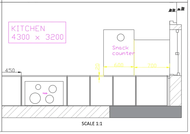
14. Enter the command "VIEW" and select the view name snack counter
15. Zoom and pan the viewport to make the view fit in the viewport.
16. Lock the viewport
17. Go to paper space and with command "T" enter the text SCALE 1:1.
18. Similary in model space click on third viewport .
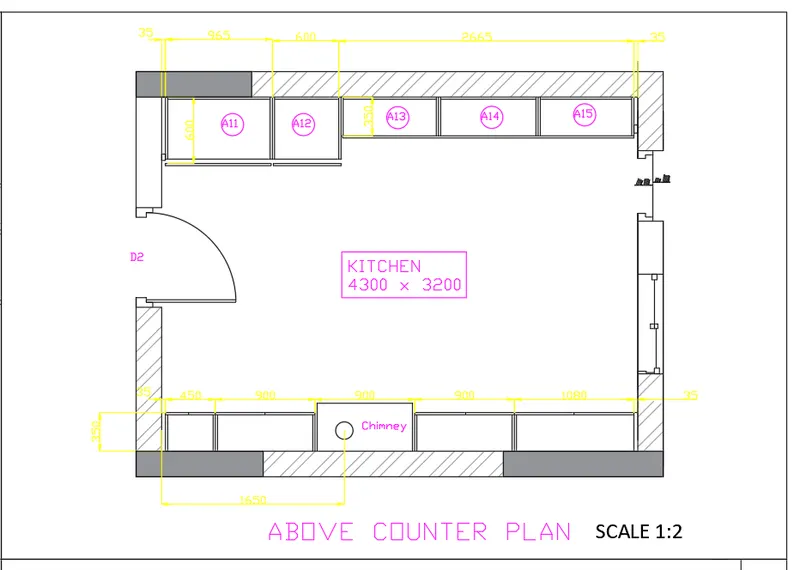
19. Enter the view above counter plan .
20. Zoom and pan the viewport , so that the drawing fit in it.
21. Lock the viewport.
22. Go to paper space and with command "T" enter the text as ABOVE COUNTER PLAN and SCALE 1:2 with text height 150.
23.Similary in model space click on third viewport .
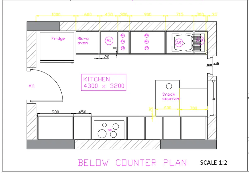
19. Enter the view below counter plan .
20. Zoom and pan the viewport , so that the drawing fit in it.
21. Lock the viewport.
22. Go to paper space and with command "T" enter the text as BELOW COUNTER PLAN and SCALE 1:2with text height 150.
c. Creating a plot
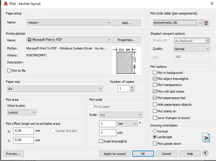
23. Use "PLOT" command , plot dialogue box appears.
24. Paper size is selected as A4 and name is given as A4, printer name ad print to pdf
25. Select what to plot as layout , and select pen assignment as monochrome.
26. Preview the print
27. Select ok to convert to pdf .
RESULT:-
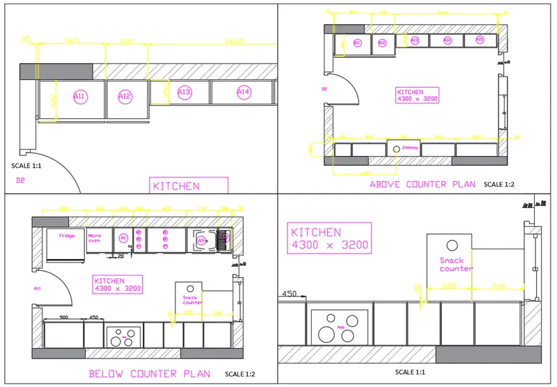
FINAL SKETCH OF KITCHEN LAYOUT WITH DIFFERENT VIEWS.
a. Different view of kitchen for layout in model space is created.
b. The layout with four viewports, with A4 sheet is created.
c. A plot is created.
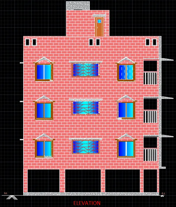
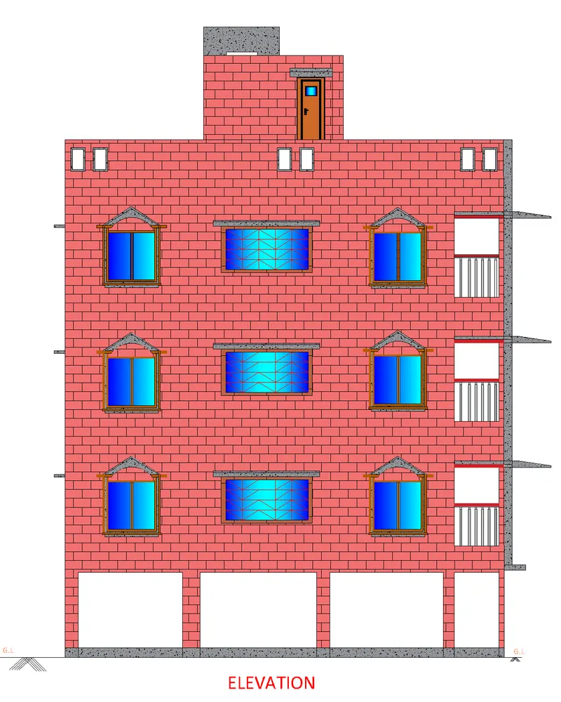
AIM:- To Create the elevation of the plan created in the Challenges 7 and apply proper hatch in the walls, doors, windows, and other architectural elements. Refer to the dimensions in Plans and sections in Challenges 7.
INTRODUCTION:-
To draw the Plan and Sections according to the provided Figures, I have used several autocad commands like- line,circle, rectangle, extend , offset, trim,erase,hatch, plot, etc., and I set dimension (Decimal) and select milimeter in Autocad. Moreover, I set limits with command "Limits", specify the left corner points ans right corner points and then enter zoom all("z-a") in this drawing. Also, I used dimesion command for measuing the dimensions in Autocad along with text command to write drawing name. Apart from that, I have assumed several data for drawing this sketch.
PROCEDURE:-
Open Autocad and type a command "Unit" and press enter, then set unit as Decimal and set angle in degree- base angle is east -mark angle direction as anticlockwise. Type a command "DIMSTYLE" and press enter, then click to modify and go to primary unit tab and set it Decimal and set the precision to 0.0 and cick ok.
DRAWING PROCEDURE FOR CREATION OF SECTION:-
- Open plan layout from challenge 7.
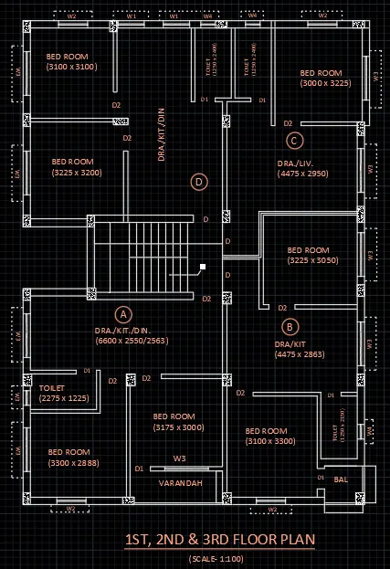
- Project the walls and columns from the plan using line command.
- Mark a vertical line showing ground level.
- Project the windows and ventilators and give the height 2100mm.
- Draw windows and varandah as per given sketch and assume dimensions as per industry standards.
- Offset slab of 100mm thickness and draw the beams.
- Show the section of windows wherever the section line cuts the windows.
- With multileader, text size -250mm and leader point as 2, write the text.
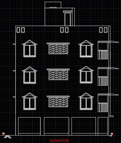
- Apply hatch in windows, doors and walls and other places as per your own assumption.
c. Creating a plot
23. Use "PLOT" command , plot dialogue box appears.
24. Paper size is selected as A4 and name is given as A4, printer name ad print to pdf
25. Select what to plot as layout , and select pen assignment as monochrome.
26. Preview the print
27. Select ok to convert to pdf .
RESULT:-
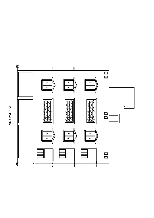
FINAL SKETCH OF ELEVATION VIEW.
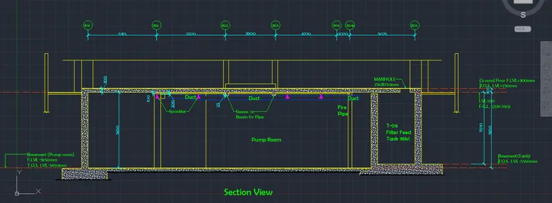
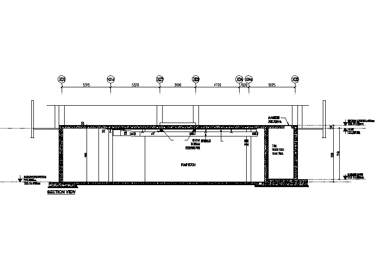
AIM:- To Create the section view of an industrial building as shown in Figure. Provide appropriate hatches and dimensions wherever required. Also, provide annotations to the drawing.
INTRODUCTION:-
To draw the Plan and Sections according to the provided Figures, I have used several autocad commands like- line, rectangle, extend , offset, trim,erase,hatch, plot, etc., and I set dimension (Decimal) and select milimeter in Autocad. Moreover, I set limits with command "Limits", specify the left corner points ans right corner points and then enter zoom all("z-a") in this drawing. Also, I used dimesion command for measuing the dimensions in Autocad along with text command to write drawing name. Apart from that, I have assumed several data for drawing this sketch.
PROCEDURE:-
Open Autocad and type a command "Unit" and press enter, then set unit as Decimal and set angle in degree- base angle is east -mark angle direction as anticlockwise. Type a command "DIMSTYLE" and press enter, then click to modify and go to primary unit tab and set it Decimal and set the precision to 0.0 and cick ok.
DRAWING PROCEDURE FOR CREATION OF SECTION VIEW OF AN INDUSTRIAL BUILDING:-
- Change snap and grid spacing to 100
- Change major line every grid line to 10
- Turnoff adaptive grid
Step 1: Creating Layers
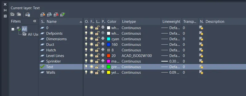
Open Layer properties and create new layers by clicking on new layer or right click on any layer and select new layer to create new layer
Layers are created as follows
Step 2: Creating Outer Walls
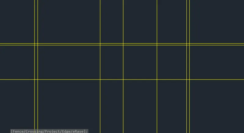
- Draw a horizontal x line at any point on the screen
- Offset the line to top to a distance of 5850mm
- Offset the last offset line to a distance of 300mm to the top
- Draw a vertical xline on any point on the top horizontal xline
- Offset the line to right to a distance of 10635mm
- Offset the last offset line to distance of 3900 to the right
- Offset the last offset line to distance of 5740 to the right
- Offset the last offset line to distance of 5025 to the right
- Offset the left and right edges to a distance of 500mm to left and right respectively
Trim off the outer edges
- Offset the bottom edge of the top floor to a distance of 30mm to the bottom
- Offset the last offset line to a distance of 70mm to the bottom
- Offset the last offset line to a distance of 100mm to the bottom
- Draw the sprinkler pipe as shown in figure along with the duct pipe with given dimension and duct pipe thickness is 300mm

Draw the manhole cover of 750mm wide at the right top edge of filter feed walls as follows
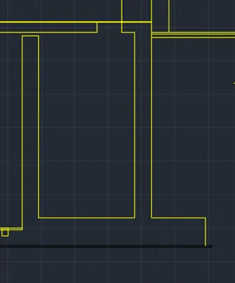
The bottom addition thikness of the pump room slab is drawn using different layers as follows

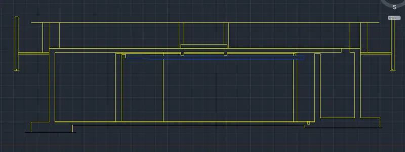
The final figure after drawing columns and slabs along with top lines above ground floor is as follows
Step 3: Creating Blocks and attributes
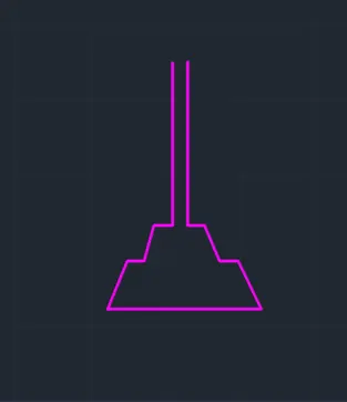
Creating sprinkler
- Sprinkler is created from line command drawing two parallel line
- Two rectangles are drawn with one bigger than the other and stretching the bottom edges
Creating Attribute
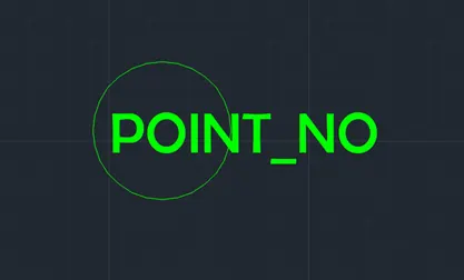
- Draw circle of radius 500mm
Go to insert tab and click on define attribute in block definition palette or type ATTDEF in command box
In the popup box
- Set mode as ‘lock position’
- Set tag as ‘Point_No’
- Set Prompt as ‘What is the Point Number?’
- Set default as ‘X0’
- Set justification as ‘left’
- Text style as per drawing text style ‘Berlin Sans FB’ and press okay
- Place the attribute in the center of the circle as follows
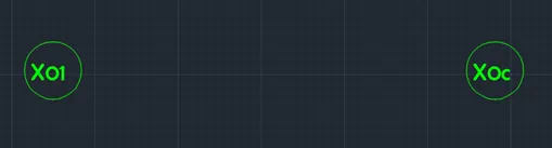
After inserting this block
Step 4: Hatching
Type Hatch in command box and click on hatch command
Click on options or settings in the command box
- Select hatch and type as predefined
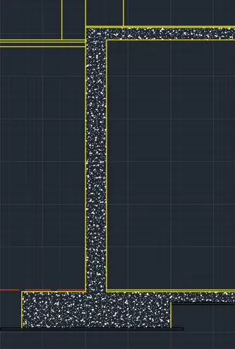
- Select pattern as AR-CONC for the walls and colour as white
- Set angle as 0 and scale as 1 as per the grid settings of drawing
- Click on preview for checking the hatch
- Press ok to assign the hatch
- Select the regions of wall for hatch
Similarly hatch the bottom edges of the pump room with solid black color
Result:
The result of this challenge consists of underground pump room of an industrial building and filter feed. Both are nearly 6m below ground level. Sprinklers are placed at a top of pump room with duct at the top along with fire pipe. Filter feed is 5.55m blow ground level. Text and multileader annotations are created as per the drawing. Dimensions are also given as per the given drawing.
- All the dimensions mentioned are in meters
- Dimensions and text are assigned using dimension layer and text layers
- All components are assigned with respective layers and hatching is done.