Creating Kitchen layout, Hatching of Architectural elements and sectional view of an Industrial Building in AutoCad
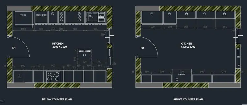
Aim-To create a kitchen layout with blocks and hatching as shown in figure.
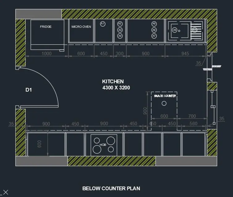
Introduction-In this below and above counter plan of kitchen layout is given with hatching and blocks. Here door and windows are in block provided. All dimension are in mm.
-D1=1000x2100 W1=800x800
Procedure-
-Set unit, limit, and dimension style
-In dimension style take new style with name of Arial and select text font Arial also
-Draw rectangle of @4300,3200
-Take offset of 230mm outside the rectangle, explode both the rectangle
-Take mid point of inner rectangle and make opening for door by offset command
-Now as per given dimension start draw below part of kitchen by taking offset respectively
-The dotted line is shown this is take with scale of 10 unit
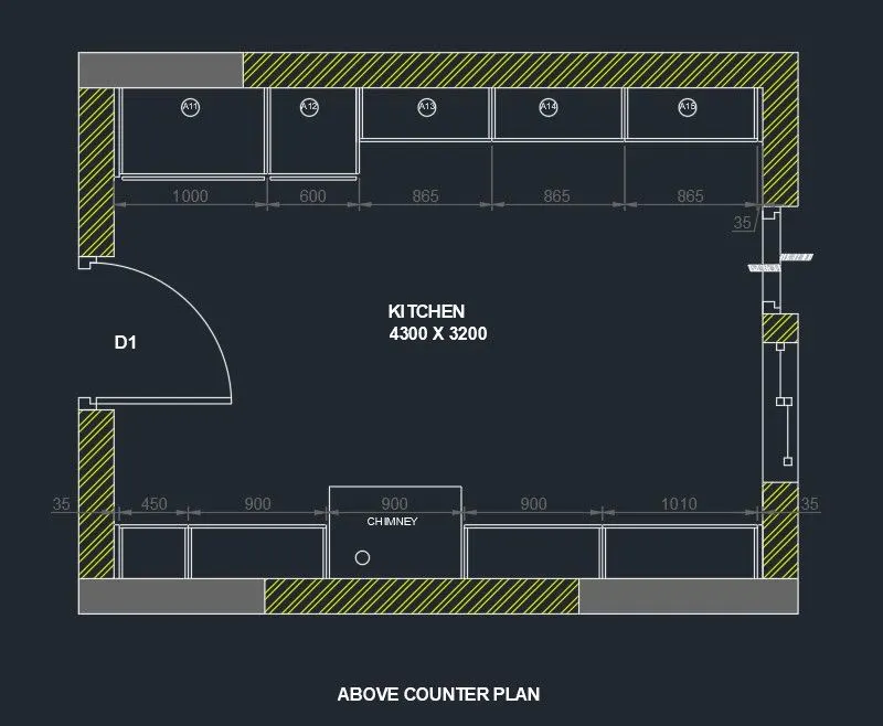
-Similarly as per given dimension start drawing upper part of kitchen
-Trim extended lines
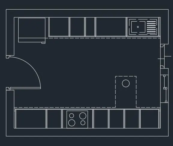
-For door draw a line 1000mm at one of end of line draw a line of 80mm vertical, 80mm horizontal , downward 40mm again towards right 20mm and 40mm downward. mirror this to other end of line. Draw a circle , trim extended cirle
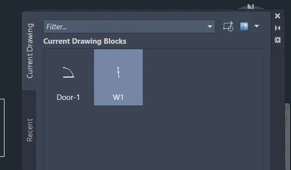
-To block door type b enter give name D1 , pick point, select object , ok
-For window draw a line of 800mm at one end draw rectangle , copy that rectangle at mid oint of line and other end of line now as per draing arrange it block it with name of W1
-LA enter make a layer for dimension
-Give dimension as per drawing and set in layer
-DT enter for text
-H enter for hatching, provide solid hatching as per given diargam and ANSI32 respectively
-Copy this plan delete all inner dimension, lines, text
-As per shown in figure start drawing here
-Take line, offset ,trim extended lines aas per given figure with given dimension respectively
-DT enter for text
-Given dimension and make it in layer
Result-
The final sketch of this kitchen layout is provided with their respective names
Aim-To create a elevation of plan created in challenge-7
Introduction-Here we can use XREF command for plan which is drawn in challange-7. Take dimension from challenge-7. Provide proper hatching
Procedure-
-Set unit , limit, dimension style
-In dimension style take new style with name of Arial and select text font Arial also
-By XREF command attatch drawing of challange-7 in this drawing
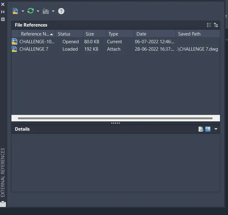
-From challenge-7 we can take dimension also
-Now take projection horizonatal lines to draw a elevation
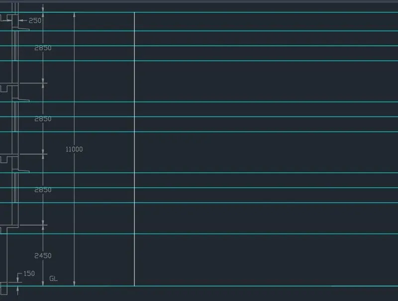
-As per drawing dimesion and projectionn lines trim unwanted lines and draw the windows, tank , door
-Draw chajja as per given drawing
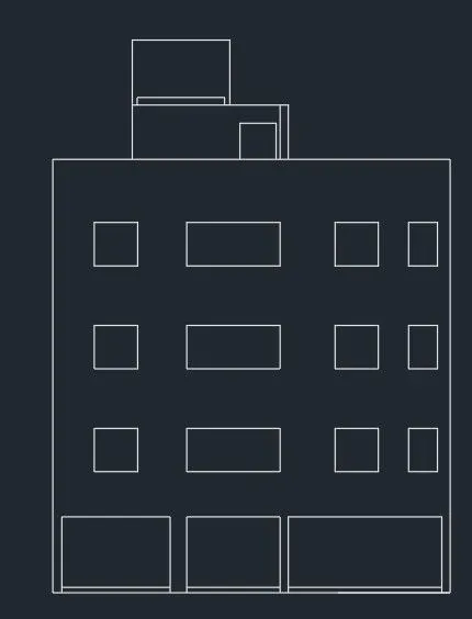
-Now draw a panels for windows
-H enter for hatching it properly
-For door using wood hatching with gradient. The wood hatching setting is in front of boundry and gradient send back to boundary.
-Similarly, brick hatching is in front and gradient hatching send back to boundary.
-DT enter for text
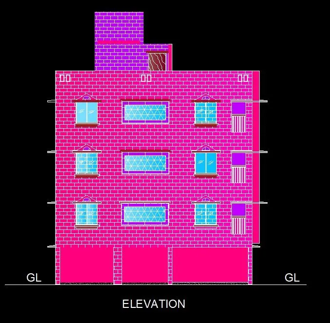
Result-
-In this by using XREF command projection are done, dimension taken from challange-7.
Aim-To create a section view of industrial building with proper hatching
Introduction-This a section view of industral building with hatching and dimensions are in mm. Some of dimensions are assumed.
Procedure-
-Set unit, limits, dimension style
-In dimension style take new style with name of Arial and select text font Arial also
-Start drawing by line command, take offset, trim unwanted lines, as per given dimension as shown in firgure
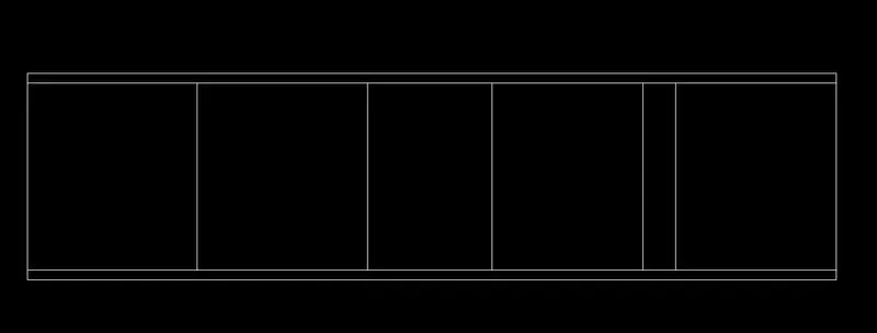
-As per given figure draw columns
-Draw remaining portios as per figure
-Show lineweight as per shown figure (LW enter)
-Give proper hatching by H enter command
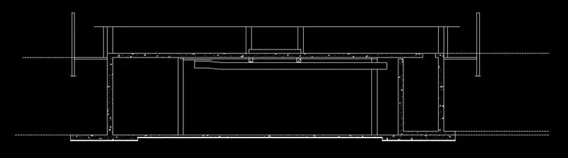
-Now provide dimensions
-Use leader ML enter
-DT enter for text
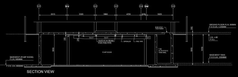
Result-
-This is the final sketch of section view of industrial building.