Creating Kitchen layout, Hatching of Architectural elements and sectional view of an Industrial Building in AutoCad
1.
AIM :
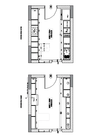
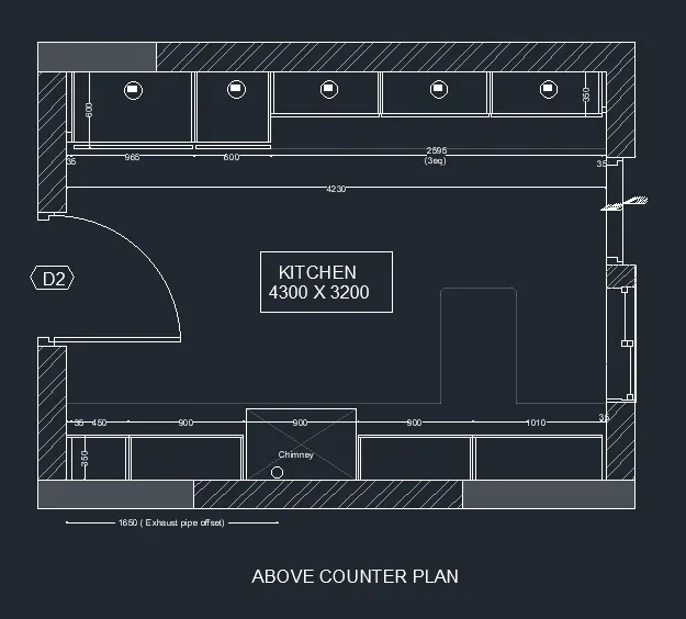
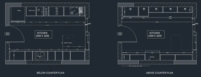
Create the layouts of the Kitchen and provide hatches pattern as shown.
INTRODUCTION :
we have used blocks wherever required. we have Provided appropriate dimensions in the plan. we have Assumed the size of doors, appliances and others as per the standards.
PROCEDURE :
step-1
- set unit to decimal milimeter
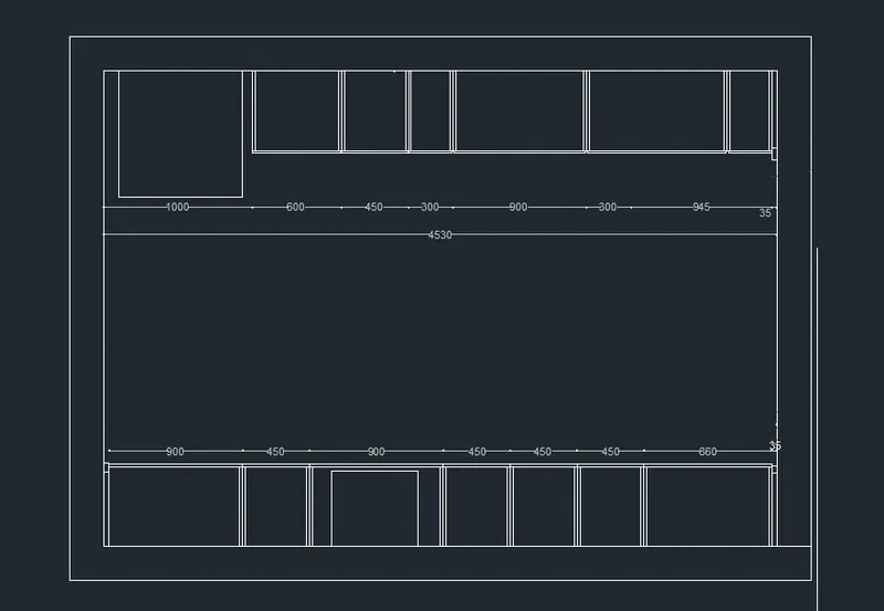
- type rec > select first corner point > give dimensions of 4300 x 3200
- type offset > offset distance 230mm > select rectangle > give offset outside the rectangle
- type explode > explode the rectangle
- note here, the given dimensions are not accurate we need to adjust the dimensions
- given width of kitchen is 4300 but its 4530 if we calculate
- we need to adjust the rectangle size
- type offset
- make offset for vertical line on left side
- make offset of 1000,600,450,300,900,300,945,35
- now make offset to top horizontal line
- give offset of 600
- assume some dimensions and make component as shown in fig
- simlilarly give offset at the bottom for vertical line on left side
- offset of 35,900,450,900,450,450,450,860,35
- now make offset to bottom horizontal line
- give offset of 600
- assume dimensions ans make component as shown in fig
step-2
- assume door width 1050
- make a door symbol using line, arc, trim command
- make a block of this door
- block > give title > select object > pick point > ok
- make a window having width 900
- make a block of this window
- block > give title > select object > pick point > ok
- make other blocks using line, array, copy, trim, command
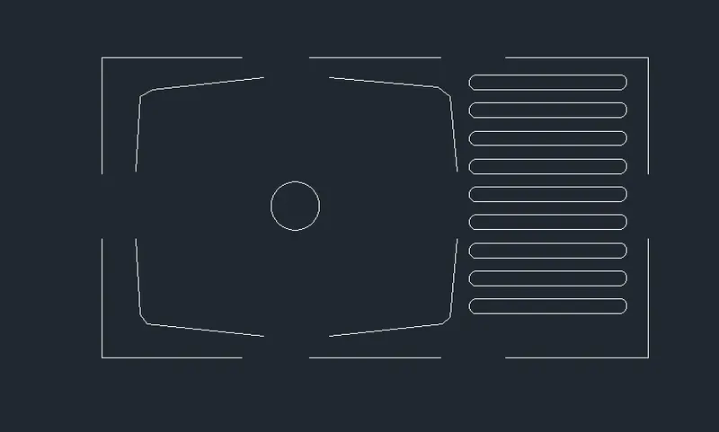
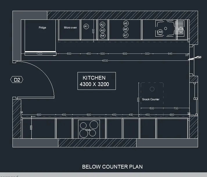
- select hatch and provide hatch to the wall
- select hatch ANSI32 adjust the scale
- select solid hatch change the colour to grey and give it to wall
- select line type dash line make snack counter of 600 x 900
- type mtext for naming the drawing
- type dimlin to provide dimensions > select arow style to dot > adjust text height > keep ext line off
step-3
- type rec > select first corner point > give dimensions of 4300 x 3200
- type offset > offset distance 230mm > select rectangle > give offset outside the rectangle
- type explode > explode the rectangle
- note here, the given dimensions are not accurate we need to adjust the dimensions
- given width of kitchen is 4300 but its 4230 if we calculate
- we need to adjust the rectangle size
- type offset
- make offset for vertical line on left side
- make offset of 35,965,600,2595
- now divide this 2595 dist line in 3 segments
- type divide > no of segment 3
- type ddptype > select point style
- now make offset to top horizontal line
- give offset of 600 and offset of 350
- assume some dimensions and make component as shown in fig
- simlilarly give offset at the bottom for vertical line from left side
- offset of 35,450,900,900,900,1010,35
- now make offset to bottom horizontal line
- give offset of 600
- assume dimensions ans make component as shown in fig
- we have made a block of door and window
- type insert > insert the door
- paste it
- type insert > select window > drag in drawing
step-4
- select hatch and provide hatch to the wall
- select hatch ANSI32 adjust the scale
- select solid hatch change the colour to grey and give it to wall
- type mtext for naming the drawing
- type dimlin to provide dimensions > select arow style to dot > adjust text height > keep ext line off
RESULT :
we have Created the layouts of the Kitchen and provide hatches pattern as shown.
2.
AIM :
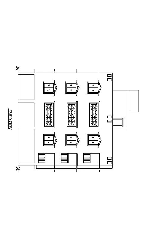
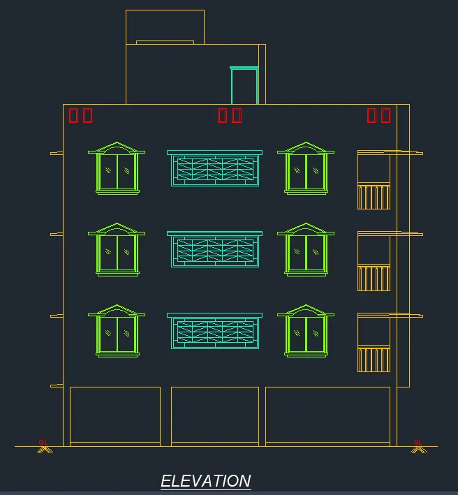
Create the elevation of the plan created in the Challenges 7 and apply proper hatch in the walls, doors, windows, and other architectural elements. .
INTRODUCTION :
We have Referred the drawing from week 7 challenge. we have referred the dimensions in Plans and sections in Challenges 7
PROCEDURE :
- open the drawing of week-7 challenge
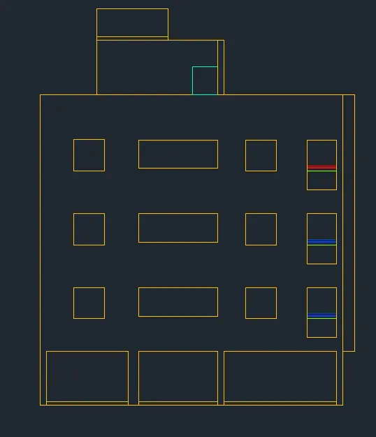
- type xline > make projections as shown in fig.
- using this projections make all the components of building
- use some already made layers
- use line, rectangle, trim, fillet command
- 
- make railing sketch to balconies
- type line and assume some dimensions
- and make rectangle and rail symbol
- type array > select path array > make 6 no of array having same spacing
- now copy this rail sketch paste it to all the balconies
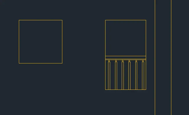
- draw other components
- type offset and make rectangle outside the rec
- type explode explode the inner rectangle
- using line and offset command make other projections
- for inner rec which has explode
- type divide > no of segments
- do this process for vertical and horizontal line
- using this point type line and join it
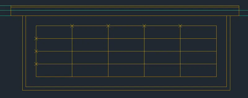
- now type line and join the line as shown in fig.
- and copy this and paste on similar boxes
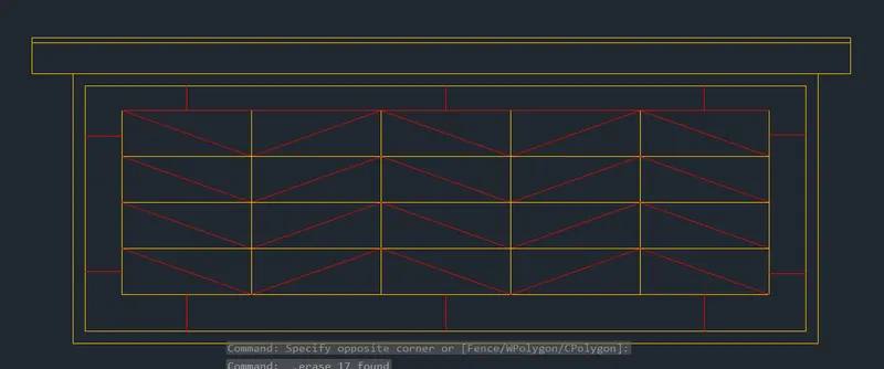
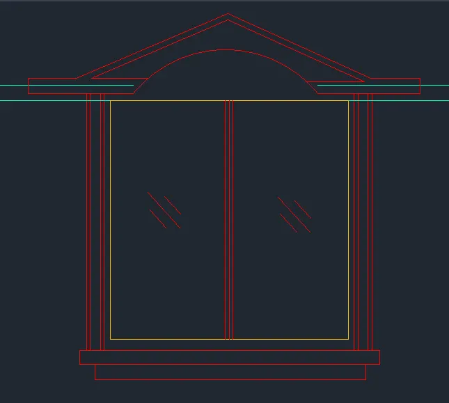
- now make pattern for window
- use line, arc fillet and assume some offset distance make following diagram
- copy this fig and copy on other simliar windows
- 
- make other component of drawing
- using line and rectangle command
- using mtext name the drawing adjust height of thn text.
RESULT :
We have Created the elevation of the plan created in the Challenges 7
3.
AIM :
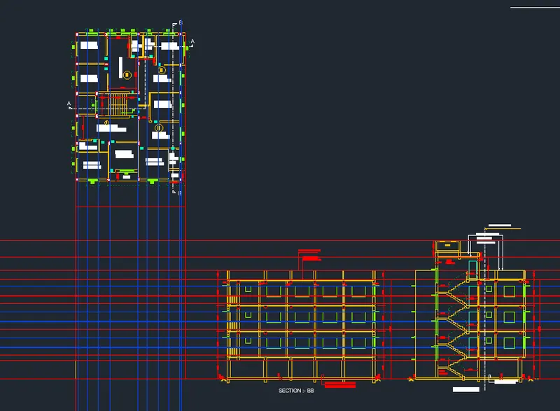
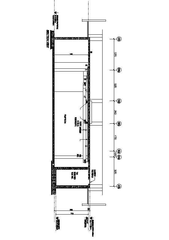
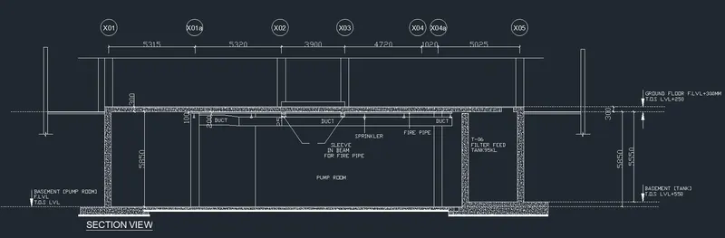
Create the section view of an industrial building as shown in Figure.
INTRODUCTION :
In this drawing we have Provided appropriate hatches and dimensions wherever required. Also,we have provided annotations to the drawing.
PROCEDURE :
step-1 :
- set unit > decimal > milimeter
- type xline in x-direction and y-direction
- assume hatch portion width as 400
- type offset and make vertical offset of 400
- give offset of 300 to bottom horizontal line and then offset of 25
- and then offset of 5850 then offset of 300 and then 25
- at top we have some dimensions
- first make wall thickness at top vertical line as 500
- make offset of 250 because we have dimension which start from centre of width
- make continuous offset of 5315,5320,3900,4720,1020,5025
- give offset to this line to left and right side
- give offset of 250 at both side
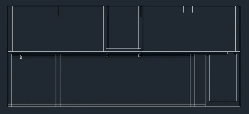
- assume some dimensions and make following digram
step-2
- sime dot line use in diagram
- select lintype > dot line > select for drawing
- select hatch and give hatching to drawing
- select concrete hatching > scale it properly > insert in drawing
- select solid hatch > insert in drawing
- select hatch ANSI31 > scale it > insert in drawing
- type mtext and name the drawing
- type dimstyle > adjust text height and text style
- type dimlin and give dimension to diagram.
- for some places use q-leader command to name the drawing
RESULT :
we have Created the section view of an industrial building as shown in Figure