Creating Kitchen layout, Hatching of Architectural elements and sectional view of an Industrial Building in AutoCad
1.Create the layouts of the Kitchen and provide hatches pattern as shown. Also, use blocks wherever required. Provide appropriate dimensions in the plan. Assume the size of doors, appliances and others as per the standards.
Alm: To draw the kitchen layout using AutoCAD software.
Introduction:
Various commands used
- QNEW command
- UN command
- REC command
- Offset command
- Explode command
- Circle command
- Line command
- Ed command
- Mtoxt command
- Rcommand
- Block command
- Insert command
- ADC command
- DIMLIN command
- DIMCONT command
- Trim command
- Extend command
Procedure:
- Open AutoCAD software
- Type QNEW in command box, press enter, and choose default setting as metric.
- Type UN in command box and press enter
- Select the unit of measurement as architecture with the precision 0,
- Type REC in command bax and press enter
- Click on dimension option, specify length as 4300 and width as 3200, press enter and draw the rectangle -Take offset of 220 mm in external side to the rectangle.
- Type explode in command box, press enter and explode the inner rectangle,
- For drowing the opening draw the line at midpoint of left edge of rectangle inside the thickness - Take off of 500 units to both side of just drawn line
- Trim the lines to create opening using trim tool
- For drawing the hings choose polyline tool and specify first point as corner point of opening, draw the line in vertical direction of 70 unit length followed by horizontal line of 90 unit length, followed by 40 unit length downward line followed by 40 unit length horizontal line in right direction followed by downward line of 30 unit length
- From the midpoint of thickness draw the vertical line of 60 unit length using line tool, followed by horizontal line in right direction
- Draw the door using circle tool and trim the extra portion of circle.
- For drawing the window take offset of 600 units in upward direction to bottom inner horizontal line.
- Draw the hinge using polyline tool.
- For that draw vetical line of 30 unit length followed by horizontal line of 120 unit length followed by 10 unit length downward line followed by horizontal line of 110 unit length followed by 20unit length vertical line.
- Draw the four rectangles of 45 x 45 unit size and place it at appropriate positions and join the midpoints of rectangle using line tool.
- Similarly draw the second window.
- Take offset of 600 units to the inner bottom horizontal line in upward direction.
- Extend line in thickness of wall and trim the extra line.
- Using line tool draw the horizontal line in right direction of 600 unit length followed by 900 unit vertical line followed by 600 unit length horizontal line followed by vertically downward line of 900 unit length followed by horizontal line intersecting vertical inner face of wall
- Typo rec in command box, press enter, specify first corner point as corner of rectangle, select dimension option.
- Specify length 1000, width 230, and draw the rectangle inside the thickness of wall
- Similarly draw the rectangles as a column of size 1200x230 and 1400 x 230 in bottom left and bottom right comer of rectangle inside the thickness of wall.
- Type H in command box, press enter, select the ANSI132 hatch pattern with the scale 10 and pick internal point inside thickness of wall.
- Again, type H in command box, press enter, select the solid hatch pattern and pick the internal point inside the rectangle as column and fill it.
- Type CO in command box press enter, specify base point and copy whole drawing to create above counter plan
- For drawing below counter plan, type O in command box, press enter, specify offset distance 35, press enter
- Take offset inside the rectangle from inner right face if rectangle,
- Similarly take offset of 560,450,450,450,900,450,000 and 35 units in the same direction from their respective last taken offset
- Take offset of 20 units in both direction to the drawn offset and trim the extra portion of lines using trim tool
- Type O in command box press enter, specify offset distance 600, press enter, take offset inside the rectangle from inner bottom horizontal line rectangle.
- Similarly draw the other appliances of kitchen using offset, line and trim tool.
- Type rec in command box, press enter, select dimension option, specify length as 675 and width as 530 and draw the rectangle as hob.
- Type C in command box and draw the small four circles inside the rectangle.
- Type B in command box, press enter, name the block as HOB, select the rectangle, pick the point as midpoint of bottom edge of rectangle.
- Type in command box, press enter, select the hob block and insert it to the appropriate position.
- Type ADC in command box, press enter, select the en-us option from folder tab, select the design center, select the kitchens dwg, select the blocks option followed by selection of refrigerator-2 door-36 in top option and insert it to the location of fridge.
- Similarly draw the below counter plan of layout of kitchen.
- Type ST in command box, select the font name as Arial, height of text as 50 units and select ok.
- Type MTEXT in command box and press enter.
- Specify first corner point and type the text content.
- Select the text and copy it to required position using the copy tool from the ribbon of home tob.
- Type ED in command bax and press enter box and edit the all text as per required content.
- Choose the multiple option from the command.
- Type dimin in command box and press enter
- Spacify first extension line origin and second line extension origin and give the dimensions to all the lines.
- Type DIMCONT in command box press enter.
- Select the dimension which is required to be continued and continue the dimensions.
Result:
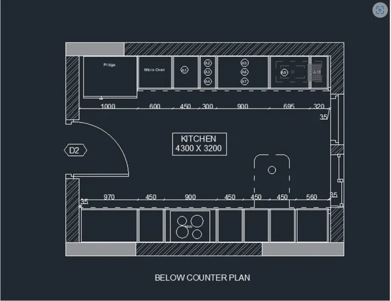
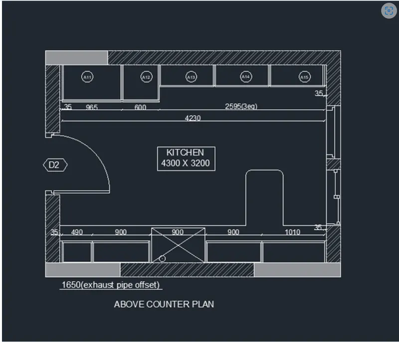
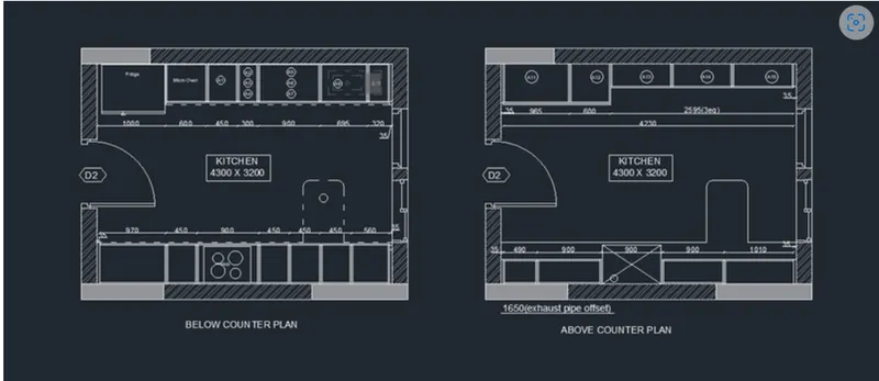
The layout of kitchen is created in AutoCAD software using above mentioned procedure as shown below.
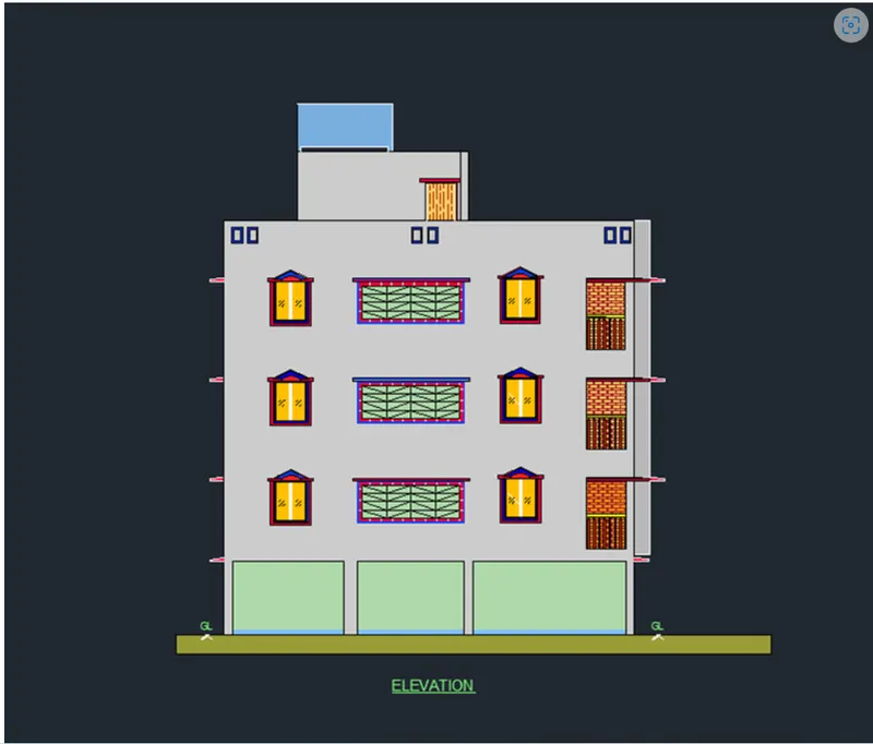
2. Create the elevation of the plan created in the Challenges 7 and apply proper hatch in the walls, doors, windows, and other architectural elements. Refer to the dimensions in Plans and sections in Challenges 7. Refer to the elevation that needed to be created
Alm:
To create the elevation of plan created in challenge 7 and apply hatches in architectural elements using AutoCAD software.
Introduction:
Various commands used
- XL command
- Offset command
- Trim command
- Hatch command
- HEDIT command
- Arc command
- Copy command
- Erase command
- RECcommand
Procedure:
- Open AutoCAD software, go to application menu, select the open option, and select the challenge 7 drawing file and open it.
- Type XL in command box, press enter, select the vertical option from command box, press enter, and draw the projection lines from each column to create the ground floor elevation.
- Again, type XL in command box, press enter, select the horizontal option from command box, and draw the horizontal line.
- Using trim tool trim the extra portion of line.
- Type O in command box, press enter, specify offset distance 150 units and draw offset in upward direction to create the plinth level.
- Similarly take offset of 2500 units in upward direction from ground level horizontal line.
- Type O in command box, press enter, specify offset distance 2850 units and draw two offsets in upward direction to create the floor levels.
- Type O in command box, press enter, specify offset distance 1000 units and draw offset in upward direction to create the parapet wall from the top horizontal line.
- From the roof level draw offset of 2500 in upward direction followed by offset of 600 and 1200 units in upward direction.
- Trim the undesired extra projected lines.
- For drawing the window take projections from each window from the floor plan using XL tool
- Select the same line and take offset of 2100 units in left direction for lintel level followed by offset of 900 units to create the sill level from the same line.
- Trim the extra lines using trim tool to create the window opening.
- Trim the extra projected lines using trim tool to create the column junction with the wall.
- Type O in command box, press enter, specify offset distance 50 and take offset inside the rectangular window opening followed by offset of 25 units inside the rectangle.
- Using line tool draw the vertical line from midpoint of top and bottom faces of rectangles and take offsets of 25 unit distances towards both sides of lines.
- Similarly draw the chhajja and other portion of window using line tool.
- Type H in command box and press enter, select the solid hatch pattern assign it color and fill it inside the window portion.
- Type H in command box press enter and select the GOSTGLASS hatch pattern with scale 75 an fill it inside the window portion to create the window glass.
- Similarly draw all the windows.
- Type CO in command box press enter, select the first floor windows, press enter, select the base point as loft bottom corner and copy it to upper floors.
- Type E in command box and erase the floor level.
- Type H in command box press enter, select the solid pattern and pick the internal point as inside the wall portion
- Similarly draw the other portion of elevation using line and hatch tool.
Result:
Elevation of plan is created in AutoCAD software using above mentioned procedure as shown below.
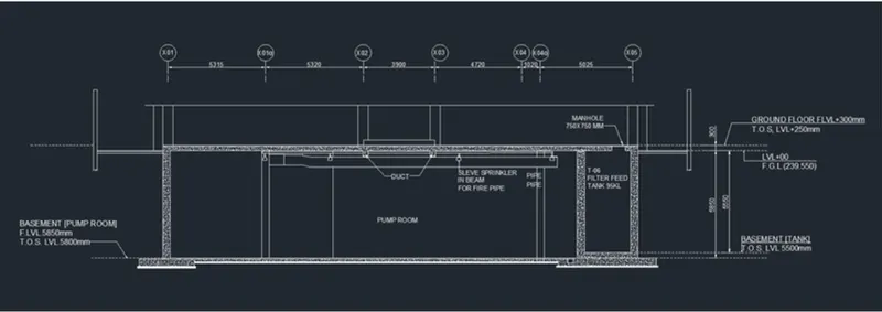
3. Create the section view of an industrial building as shown in Figure. Provide appropriate hatches and dimensions wherever required. Also, provide annotations to the drawing.
Aim:
To create the section view of an industrial building by providing hotches and dimensions in AutoCAD software
Introduction:
various commands used
- QNEW command
- UN command
- XL command
- Line command
- Offset command
- Hatch command
- Line command
- Trim command
- ST command
- MTEXT command
- ED command
- Copy command
- Qleader command
- Multileader tool
- Circle command
- DIMLIN command
- DIMCON command
Procedure:
- Type ONEW in command box, press enter, select the default setting as metric and select ok.
- Type UN in command box, press enter, select, measurement unit as decimal with the precision 0.
- Type XL in command box, press enter, draw the horizontal line.
- Type O in command box, press enter, specify offset distance 5850 units and take offset in upward direction Similarly take offset of 300 units in the upward direction.
- Type XL in command box, press enter, select the vertical option from command box and draw the vertical line.
- Trim the extra projected line using trim tool.
- Type O in command box, press enter, specify offset distance 5315 units and take offset to the vertical line in right direction
- Similarly take offset of 5320, 3900, 4720, 1020 and 5025 units in the same right direction to the just drawn vertical line.
- Type O in command box, press enter, specify offset distance 200 units and take offset to the first second sidh and seventh offset vertical line in right and left direction.
- Similarly draw the upper portion of section using line tool.
- Using the trim tool trim the extra portion of lines.
- Type O in command box, press enter, specify offset distance 2500 units and take offset to the second rightmost
- vertical line in left direction followed by offset of 400 units in the same direction.
- From the bottom horizontal line take offset of 300 units in downward direction.
- Type O in command box press enter, specify offset distance 250 units and take offset to the same line in downward direction
- Trim the extra projected lines using trim tool to crate the desired shape.
- Type O in command box, press enter, specify offset distance 50 units and take offset to the second top horizontal line in downward direction.
- Type O in command box, press enter, specify offset distance 100 units and take offset to the just drawn offset in downward direction
- Similarly using the line tool draw the remaining pipes and trim the extra lines using trim tool.
- Type H in command box, press enter, select the AR-CONC as hatch pattern and fill the portion of section by picking internal point wherever required
- For drawing the hidden line, in properties panel click on drop down of linetype, select other option and in line type manger dialog box, load the hidden line.
- Select the line which is required to convert into dotted lines and from properties panel select the loaded hidden line and convert it into hidden line.
- Using the match property tool convert the line wherever required into hidden line
- ST in command box, press enter, select font name as Arial, with text height 250 units and select apply and ok.
- Type DIMUN in command box, press enter, and give the dimensions to the lines wherever required.
- Type C in command box, press enter, and draw the circle.
- Type MTEXT in command box, press enter, specify first corner and opposite corner and type the text inside the circle such that to fit inside the circle.
- Type CO in command box, press enter, select the text within the circle along with the text and copy it to the required position. Type ED in command box, press enter, select the text and edit the text as per requirement.
- Type Qleader in command box, press enter, in leader line and annotation tab select the number of points as 3. select ok. Specify first, second and third leader points and type the text as per required content.
- In annotation tab, select the multileader option from leader panel and draw the leaders wherever required.
Result:
The section view of industrial building is created using the in AutoCAD software by following the above mentioned procedure as shown below.