Creating Kitchen layout, Hatching of Architectural elements and sectional view of an Industrial Building in AutoCad
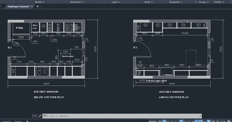
1. Aim: To create the kitchen lay out of a residence in the Auto cad using decimal system.
- The kitchen lay out is showing the utilities in the kitchen with appropraite placement and sizes of the utilities .
- The kitchen lay out displays the position of refrigirator,gas stove,wash basin and other with the use of the carpet area in the kitchen.
- The kitchen layout is helpful for the easy understanding and useful the laying of the water,gas,electrical layout according to the utilities of the room.
Procedure :
- Click on new File and create the new template for potting the drawing
- Now enter units (un) command and select the decimal system in the units and also set the precision of the units and insertion scale to mm and click on ok.
- The sizes of the kitchen can beplotted by using the rectangle or poly line or line command in the command bar,It will be more use ful to select the rectangle or poly line command to plot the size of the with accuracy.
- The kitchen room is plotted with the size of 4300x3200mm
- After plotting a kitchen room, the walls are created by using the offset command 'o' inthe command bar. The walls created with an offset distance of 150mm for the walls.
- Now after creating the walls using the trim command 'tr'in the command bar the walls are trimmed to insert the doors for access into the rooms.
- The dooors are inserted by using the block command.The doors are plotted separately to a size of 1000x2000mm in the model space and there are created as blocks and then they inserted at required room entrances.
- In the same way the windows and exhaust fan are also created as blocks and they are inserted in the place where they are required.
- The position of refrigirator to a width of 1000 mm, microoven 450 mm,wash basin and various stove units to a width of 300,500,790 are ploted and separated by the offset command using the proper offset distance.
- The minimum width of the working platform of the kitchen will be 600mm width to avoid the im balance of the utilities.
- To get the differece between the utilities of the room the line weight of the utilities are increased to evaulate the diffence.
- The Details of the kitchen are plotted with the text command. The text command will be single line text or multiline text.
- The text style is created or modified by using the 'ST' command. In the st command the text font,size,lineweight etc are modified and set as current to use the style in the lay out.
- The dimensions of the kitchnen is plotted using the dim linear command. For the clear understanding the dimension style is also created in the dimension(D) command. In this command the linetype, arrow type, size,text of the dimension,jog factor etc are modified and set as current style.
- Now using the layers command assign layers to the different components of the building if we wish to show the difference btween the utilities of the kitchen.
- New layers are created and specified colours are assigned to each layer and each individual components of the building.
- These layers help to lock or freeze the components of the kitchen.
- The final kitchen layout of the residence is obtained as shown inthe below.
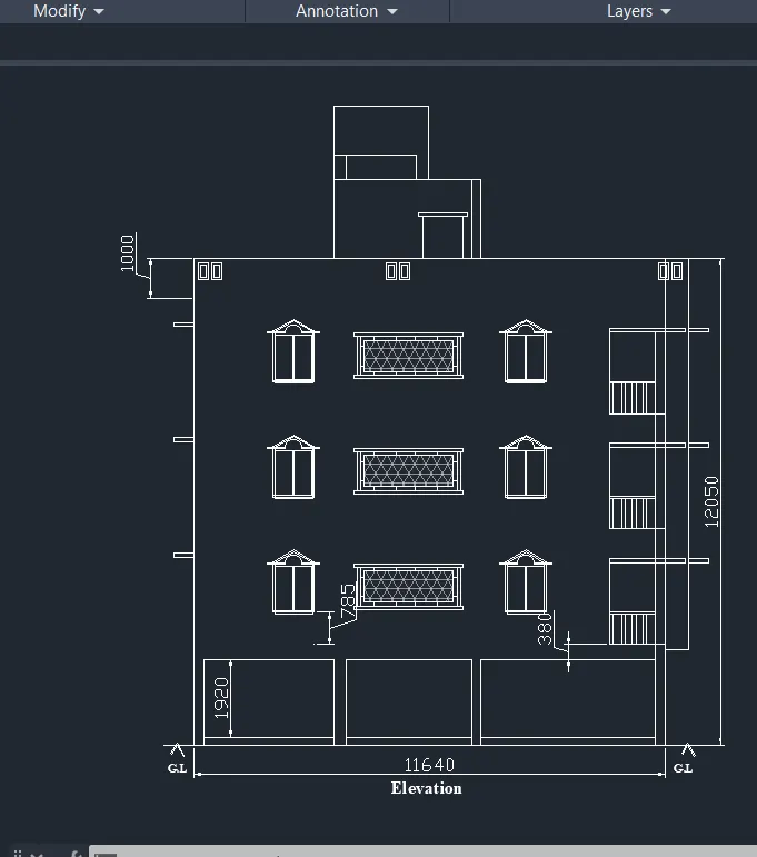
2.Aim: To create the elevation of a building in the Auto cad using decimal system.
- In a particular building elevation is one important module.The elevation gives the out look architectural appearence of the building it is made in various designs to give the pleasant look.
- The elevation is also defined as the side view of the building from all sides of the building.
- The elevtaion may decide the final outlookview of the building.
- The elevatiion is formed by the projection of lines of edges of the plan in the vertical direction, By using the reference of the plan we can prepare the elevation of the building very efficiently.
Procedure :
- Click on new File and create the new template for potting the drawing.
- Now enter units (un) command and select the decimal system in the units and also set the precision of the units and insertion scale to mm and click on ok.
- The Elevation is prepared by the projection of the lines from the plan in the vertical direction.The projection of lines can be drawn by using construction lines command entering 'XL' in the command bar which may be the very useful for the preparation of the elevation.
- From the reference of the plan the outer edge of the building lines are projected which specifies the length of the building.
- The columns are plotted from the ground line to a height of about 1920mm and at the beam line of the ground floor.
- Now again enter the 'XL'command in the command bar and the height of the building is plotted by using the lines which are projected from the sectional view of the building to a height of 12050 including parapet wall. The first floor is plotted and the second and third floor are copied.These projection lines are projected horizontally which meets the lines projected from the plan of the building.
- After forming the outer perimeter of th buildingNow the front portion slab and beam projections are plotted.
- After the slab and beam projections the doors,windows,stair case is plotted according to the height level of the bulding from the reference of the plinth beam.Firstly we need to plot the plan or elevation of the building and locate the positions of the columns at the specified points.
- The window is plotted to a size of 1000x1200mm at the sill level of 785mm from the top layer of the roof slabs.
- The balcony in the extreme corner of the building is plotted to a height of the 900 mm from the slab and the model of railing is plotted according to the specified design and shape.
- The over head tank is plotted in the left of the building and the height of the overhead tank is projected by using the sectional view of the building 1200mm.
- Now using the hatching command 'H' enter in the command bar the walls,doors,windows, beam and column projections are hatched.
- Hatching specifies the mode of material to be used for making the architectural view of the building or car case.
- Now dimlinear command the dimensions of the elevation are plotted,it will be useful if we create the new dimension style.
- Create a new text style by entering 'ST'command in the comand bar.
- Now using text or mtext command the elevation details are written to specify the different items of the model.
- Now using the layers command assign layers to the various units of the elevation model as we required.
- The final result of the elevation of the bulding is obtained as shown inthe below.
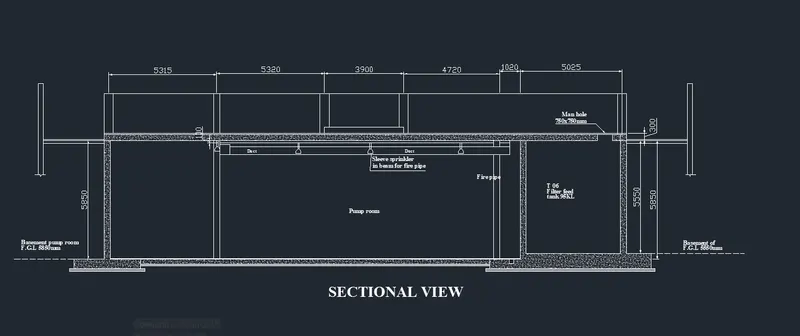
3.Aim: To create the section of a building in the Auto cad using decimal system.
- In a particular building plan is very important module and it is the cutting view of the building or any other unit.
- The section gives the two dimensions of the building unit and out of them height will be common and the other dimension is either length or width of the building unit.
- The section gives the profile of the building of materilal or internal view details of a various floors at a time.Sectional views may change according to the cutting sections of the building.
Procedure :
- Click on new File and create the new template for potting the drawing.
- Now enter units (un) command and select the decimal system in the units and also set the precision of the units and insertion scale to mm and click on ok.
- To create the section we need to cut plan at a particular direction either X or Y axis of the plan.The section cut along the X and Y axis may be either section AA or section BB.
- For the sectional view we need to fix the outer edges of the building with the length or width can be plotted with reference to the plan and the height of the building can be plotted by adding the floor heights,foundation thickess and any other units on the terrace of the building.
- The section of the industrial building is plotted by the polyline command the outer to outer edge of the section is plotted by adding the distance between the columns and the distance is25750mm and the height of the sectional columns is 5850mm.
- Now enter the off set command to a column thickness of the 300mm the outer columns and the top slab and the bottom base ment is created.
- Now enter the poly line command the basement footing under the outer columns is created to size of1500mm exceed from the columns to thickness of 450mm.
- The inner columns of the section is also plotted using the offset command to an offset distance of the 5315mm from the left column and at an offset distance of 6045mm from the right side of the section.
- The man hole for the filter tank is provided to size of 750mmx750mm size and is provided at the top portion of the tank which will provide the access in to the tank.
- The fire sprinkler are created as a block and they are inserted in the top beam of the section which will help to put off the fire during the fire accidents.
- The base ment of the tank is provided with more thickness of 300mm according to the design and to avoid the tank basement from the seepage of the liquid.
- Now using the hatching command 'H' enter in the command bar the walls,doors,windows, beam and column projections are hatched.
- Hatching specifies the mode of material to be used for making the slab and basemnet of the columns and the filter tank.
- Now dimlinear command the dimensions of the plan are plotted,it will be useful if we create the new dimension style.
- Create a new text style by entering 'ST'command in the comand bar.
- Now using text or mtext command the section details are written to specify the different items of the model.
- Now using the layers command assign layers to the various units of the sectional model as we required.
- The final result of the sectional view of the industrial bulding is obtained as shown inthe below.