Creating Kitchen layout, Hatching of Architectural elements and sectional view of an Industrial Building in AutoCad
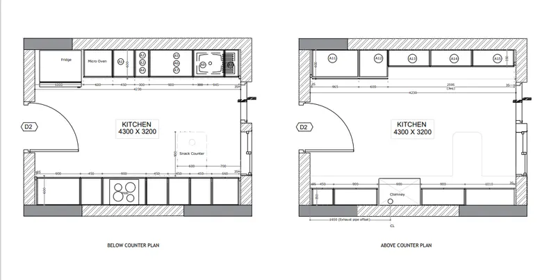
Aim - To create the Kitchen Layout with proper hatch technique and also with proper dimensions
to the kitchen as shown in the figure .
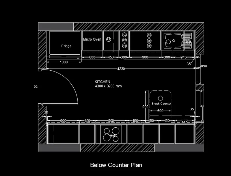
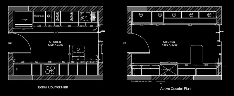
Introduction - i) In give fig there are two plans are given
a) Below counter plan
b) Above counter plan .
ii) Following commands are going to used -
a) Line
b) Rectangle
c) Offset
d) Trim
e) Arc
f) Dimension and Dtext .
Procedure -
i) Open a new drawing (Cntrl + N) with metric units .
ii) Select units to Decimal and Precision (0) with Milimeters .
iii) Lim-max and limits are also set .
Step by Step Procedure -
A) Below Counter Plan
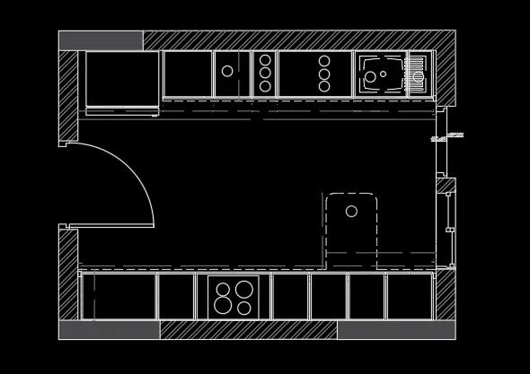
Step 1)
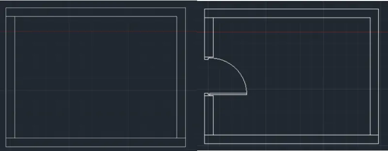
i) Command Rectangle
ii) Enter the length = 4300 mm
iii) Enter the width = 3200 mm
iv) Take the offset of 35 mm to the inner side .
v) Draw the external wall as thickness 230 mm .
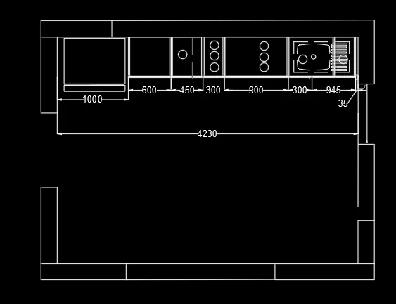
vi) To draw the Fridge -
i) Enter length =1000 mm
ii) Enter width =800 mm
vii) For Micro oven -
i) Enter length =600 mm
ii) Enter width =600 mm
viii) For Section A1
i) Enter length =450 mm
ii) Enter width =600 mm
ix) For Section A2 A3 A4
i) Enter length =300 mm
ii) Enter width =600 mm
x) For section A5 A6 A7
i) Enter length =900 mm
ii) Enter width =600 mm
iii) Remaining portion is for sink .
iv) Draw the sink as shown in fig .
Step 2)
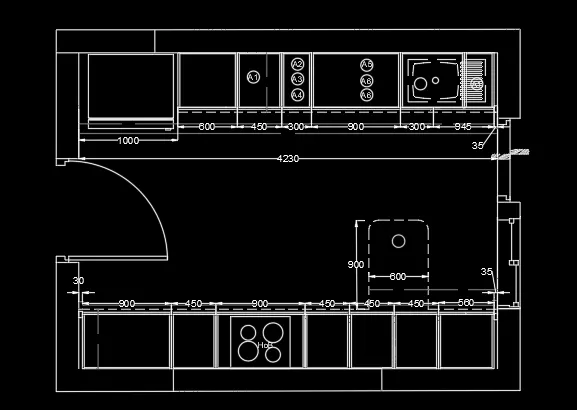
i) Give command Rec . at the bottom side
ii) Enter length = 4230 mm
iii) Enter width = 600 mm
iv) Take the offset of 35 mm in +ve X direction . and Repeat the command for for following offsets
v) Such as 900 mm , 450 mm , 900mm , 450 mm , 450 mm , 450mm , 560mm , 35 mm .
vi) Take the offset of 700 mm and draw the Snack Counter and change the layer to dotted line .
vii) Enter the length as = 600 mm
viii) Enter the width as = 900 mm
ix) Use Command Fillet and apply it the corner of top side
x) And Carry forward this horizontal to left side and join to the external wall .
xi) Command LA and Select dotted line and apply on snack counter .
xii) Draw the HOB as shown in fig .
xiii) Command Circle and give radius as 60mm and 80mm respectively.
xiv) Draw the Door D2 - Assume Dimension as (800mm x 2100mm)
xvi) Hatch -
a) Command Hatch -
b) Select type of hatch - ANSl132
c) Select the boundaries wherever hatching is required
d) Pick points where hatching needs to be done or select the object where you want to
do hatching
e) Select the boundary retention - Retain boundaries - object type - Region
f) If you want to increase the scale or modify any properties just click on the area where
you have provided hatching . Once you click you will get Hatch creation tool in
Ribbon
g) We can modify properties from ribbon panel .
Similarly ,
xvii) Repeat the command - Select stye - Soild fill - Select colour - Grey and apply it as
shown in fig .
Step 3) Give the dimensions and Annotations -
i) Command D and modify the dimensions
ii) Select text height as 75 mm
iii) Arrow size = 50 mm.
iv) Command DIMCONTINUE to get the dimensions
v) Command Dtext and select Arial font and text height 60 mm
vi) Give Annotations .
B) Above Counter Plan -
Step 1)
i) Copy the Below counter plan
ii) Trim the unwanted lines .
iii) Follow the same procedure for Above counter plan also .
Results - The Kitchen Layout as shown in the figure is drawn .
2)
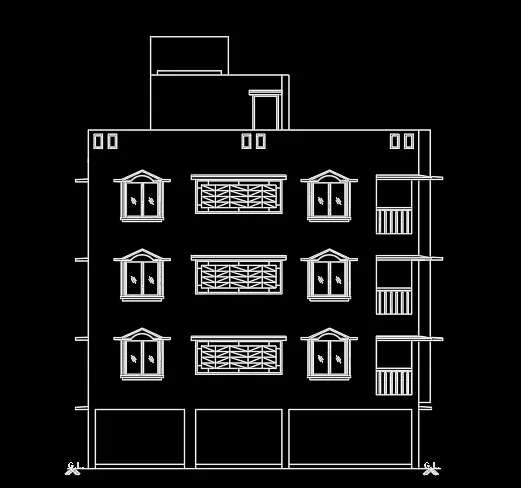
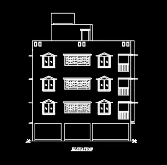
Aim - To create the Elevations of the plan created in challenge 7 .
Introduction - i) In a given fig Elevation of Challenge 7 is given .
ii) Take the reference of week 7 plan for dimensions and other things
iii) Following are the commands are used -
a) Construction line -XL
b) Line
c) Rectangle
d) Offset
e) Trim
f) Fillet
g) Dimcontinue and DText
h) Hatch
Procedure -
i) Open a new drawing (Cntrl + N) with metric units .
ii) Select units to Decimal and Precision (0) with Milimeters .
iii) Lim-max and limits are also set .
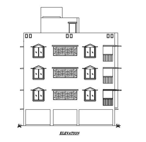
Step by Step Procedure -
Step 1)
i) To draw the elevations take the reference of week 7 challenge
ii) Take the diimensions from week 7 challenge
iii) Give the command - Line
iv) Specify the base line of a distance of 16388 mm in positive x directions .
v) Take a offset of 150mm from base line /GL
vi) Again offset of 2450 mm from GL to ground floor slab
vii) Again offset of 2850 from ground floor slab to 1st floor slab
viii) Again offset of 2850 mm from 1st floor to 2nd floor
ix) Again offset of 2850 mm from 2nd floor to 3rd floor
x) And take the offset of 1000 mm from 3rd floor to top .
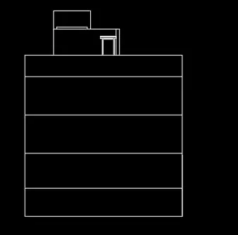
xi) Draw the window at the 1st floor ( As W3 ) Sizes are already mentioned in Challenge 7 .
xii) Command Array and Select Rectangular array to draw the same window at 2nd floor and 3rd floor .
xiii) No of rows as 3 and No of Columns are 2
xiv) Spacing between columns are 1600mm
xv) Spacing between rows are 1600 mm
xvi) Press Enter and will get same sizes of windows .
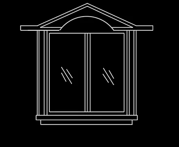

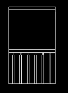
Step 2)
i) Arrange the elements which we have created earlier in elevations .
ii) Copy the same elements or use Command Array to provide the windows at 1st 2nd and 3rd floor
iii) Draw the line - Command LN
iv) Draw the horizontal line of 30mm , draw vertical line 10mm , draw inclined line of @30mm<10
v) Copy the same lintel beam to 1st 2nd and 3rd floor .
Step 3) Hatch -
a) Command Hatch -
b) Select type of hatch - Solid fill
c) Select the boundaries wherever hatching is required
d) Pick points where hatching needs to be done or select the object where you want to
do hatching
e) Select the boundary retention - Retain boundaries - object type - Region
f) If you want to increase the scale or modify any properties just click on the area where
you have provided hatching . Once you click you will get Hatch creation tool in
Ribbon
g) We can modify properties from ribbon panel .
Results - The Elevation view of Challenge 7 is created .
3)
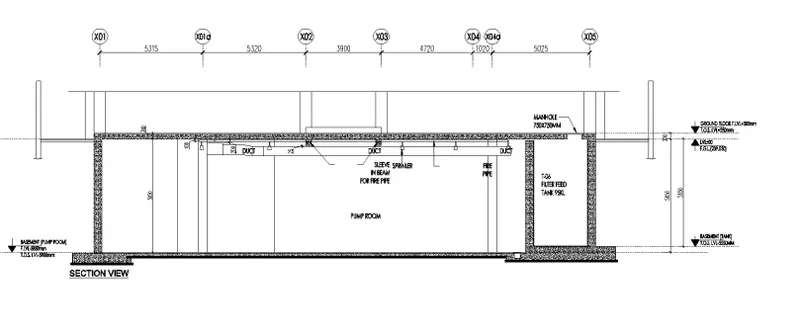
Aim - To Create the section view of an industrial building .
Introduction - i) In an given figure Section view of an Industrial building is given
ii) Dimensions are also given in fig ,
iii) Following commands are used -
a) Line
b) Rectangle
c) Copy
d) Offset
e) Trim
f) Fillet
g) Dimcontinue and DText
h) Hatch
Procedure -
i) Open a new drawing (Cntrl + N) with metric units .
ii) Select units to Decimal and Precision (0) with Milimeters .
iii) Lim-max and limits are also set .
Step by Step Procedure -
Step 1)
i) Command LN
ii) Draw the hozizontal line of distance - 25300 mm
iii) Take offset - at 5850mm of horizontal line
iv) Again take offset of 300mm of previous line
v) Command Offset - of vertical line of 5850mm at a distance 5315
v) Similarly repeat the command at a offset distance 5320mm , 3900mm , 4720mm , 1025mm ,
5025mm ,
vi) At a distance of 5315 draw a vertical line and give offset of 100mm from top
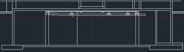
vii) Draw a duct of horizontal line 14960mm with the thickness 200mm
Step 2)
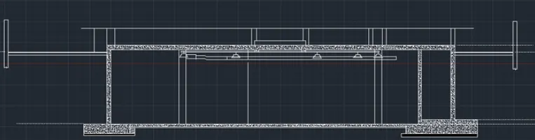
i) Command Hatch -
ii) Select type of hatch - AIR - CONC
iii) Select the boundaries wherever hatching is required
iv) Pick points where hatching needs to be done or select the object where you want to
do hatching
v) Select the boundary retention - Retain boundaries - object type - Region
vi) If you want to increase the scale or modify any properties just click on the area where
you have provided hatching . Once you click you will get Hatch creation tool in
Ribbon
vii) We can modify properties from ribbon panel .
Step 3)
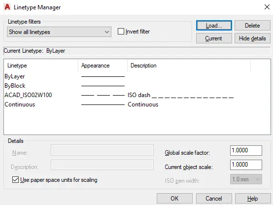
i) Command LT
ii) Select the line type - ISO Dash Dotted type
iii) Draw the Dotted Dash line at the Bottom - to show the basement line

Step 4) Dimensions and Annotations .
i) Give Command D and press enter
ii) Select Standard and then go for modify .
iii) Select Fit and USe overall Scale to 50 .
iv) Make the primary units to Decmal and precision 0
v) If you want you can on Alternate units also.
For Annotations -
i) Command DT
ii) Justify - Left
iii) Style - Arial
iv) Specify text point
v) Text ht - 30mm
vi) Text angle - 0
vii) Press Enter .
Step 5)
i) Create a grid like element naming as XO1 ,XO1A, XO2 , XO3 , XO4 , XO5
ii) Use Command DiMCONTINUOUS - to measure the continuous dimensions
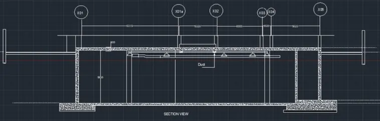
Note - All Annotations are not clearly visible in PDF .
Results - The Section view of Industrial building is created .