Creating Conceptual mass in REVIT and Creation of Sinusoidal curve and a Parametric stadium using Dynamo
PROJECT:3
Creating Conceptual mass in REVIT and Creation of a Sinusoidal curve and a Parametric stadium using Dynamo
AIM:
To create a Conceptual mass in REVIT and the Creation of a Sinusoidal curve and a Parametric stadium using Dynamo
INTRODUCTION:
Revit software is developed by the Auto desk in the year 2002. It is most useful for Architectures, Civil engineers, and MEP engineers by Drafting and Design. The Revit platform for building information modeling is a design and documentation system that supports the design, drawings, and schedules required for a building project.
Building information modeling (BIM) delivers information about project design, scope, quantities, and phases when you need it. In the Revit model, every drawing sheet, 2D and 3D view, and schedule is a presentation of information from the same underlying building model database. As you work in drawing and scheduling views, Revit collects information about the building project and coordinates this information across all other representations of the project.
The Revit parametric change engine automatically coordinates changes made anywhere—in model views, drawing sheets, schedules, sections, and plans.
Dynamo is a graphical programming interface that lets you customize your building information workflow. Dynamo is an open-source visual programming platform for designers. It is installed as part of Revit along with Revit-specific programming nodes.
QUESTION NUMBER 1:
Using Dynamo creates a set of sinusoidal points, a curve, and a surface out of the curve.
AIM:
To Use Dynamo creates a set of sinusoidal points, a curve, and a surface out of the curve.
INTRODUCTION:
Dynamo is a graphical programming interface that lets you customize your building information workflow. Dynamo is an open-source visual programming platform for designers. It is installed as part of Revit along with Revit-specific programming nodes. Dynamo is most often used to analyze BIM data, automate repetitive documentation tasks, and exchange data.
PROCEDURE:
1. Open Revit 2023 software.
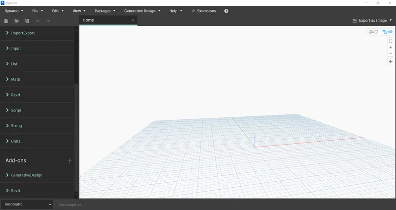
2. Now Open the Architectural template and go to the manage tab and click it dynamo to open it.
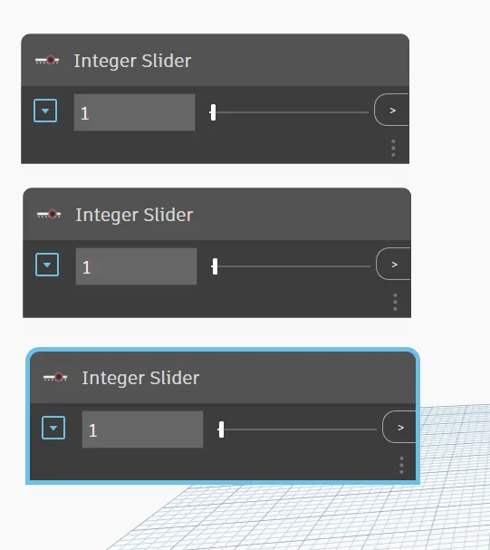
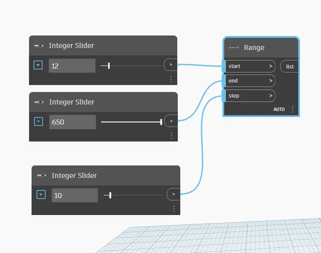
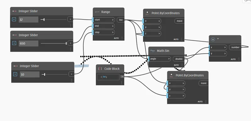
3. Now I need to create the Sinusoidal points, we need to make three Integer sliders Insert them into the model space then go to the search bar and type integer slider, and inserted it.
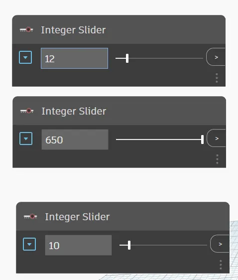
4. Now in three integer sliders, the range values are created like 12,650 and 10.
5. Now we need to create the range and go to the search bar and type Range and we get the Range option.
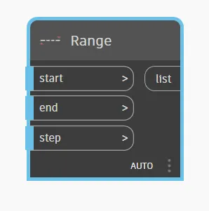
6. Now connected the integer sliders to range values like start, end, and step.
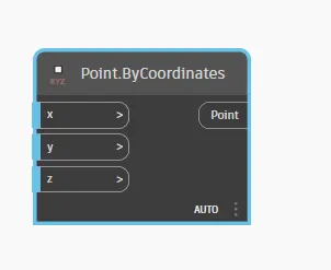
7. After that we need to create the Point by coordinates. Similarly, go to the search bar and type point by coordinates to we get point by coordinates.
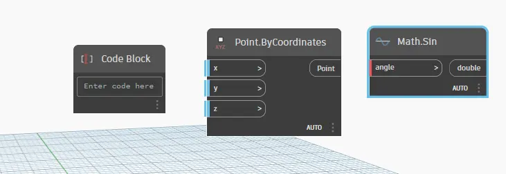
8. After that we need to make a code block and create another point by coordinates.Now inorder to make a sinusoidal curve we need Math. sin.
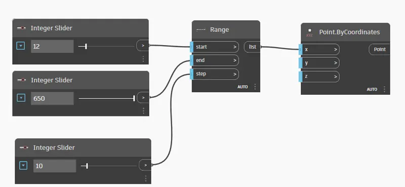
9. Now Range value list is connected to the X of the point by coordinates. Then we get the points on the entire X-axis.
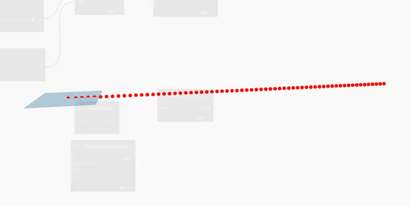
10. Now provide the code block as 50, next we need to Range list connected to the Math. sin. After that again the range list is connected to the second Point by coordinates on the X-axis.
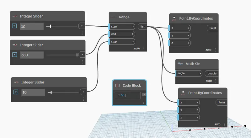
11. Now we need to make the product and type the product and inserted it into the model space.
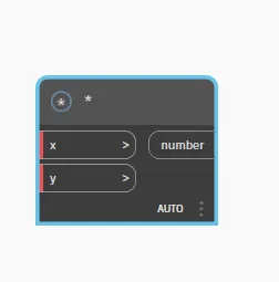
12. After that in order to make multiple sinusoidal points. Next, the code block is connected to the second point by coordinates by the Z axis. So we get Another set of sinusoidal points.
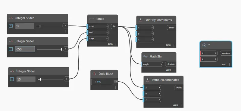
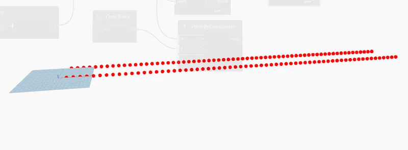
13. After that we need to connect the math. sin in the second point by coordinates on the y-axis. Similarly, we have to connect the code block to Math* on Y and Math. sin is connected to Math* on X and finally Math. sin to connected to the First point by coordinates on Z.So we will get the Sinusoidal points.
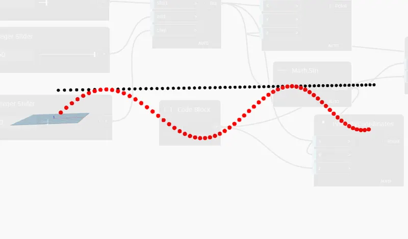
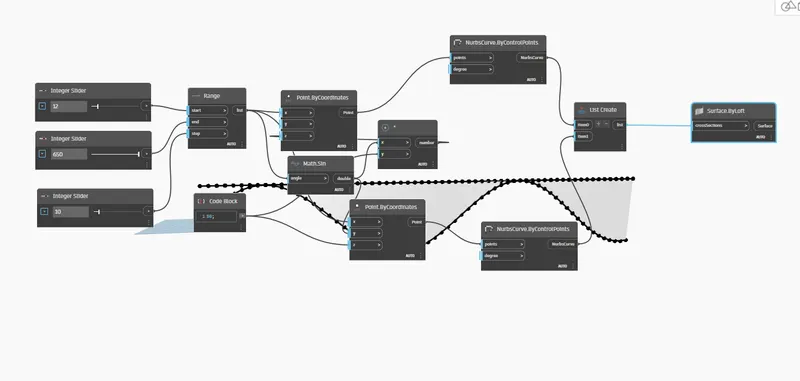
14. After that we need to make the sinusoidal curve and go to the search bar and type Nurbs by control point inserted into the model space. Similarly, we insert the List option and type list and we get a list to create.
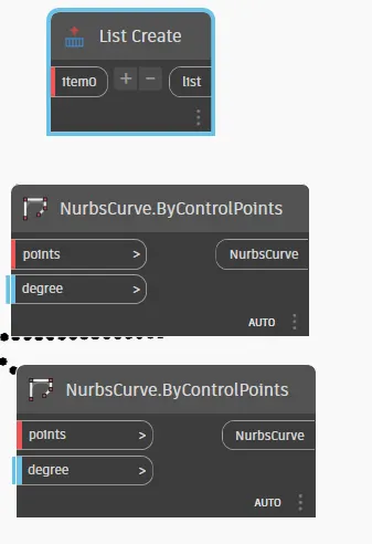
15. After that just connected point by coordinates to Nurbs curve points then we get the line in the curve. Similarly the Second point by coordinates connected to the second Nurbs curve points we get one more line in the curve.
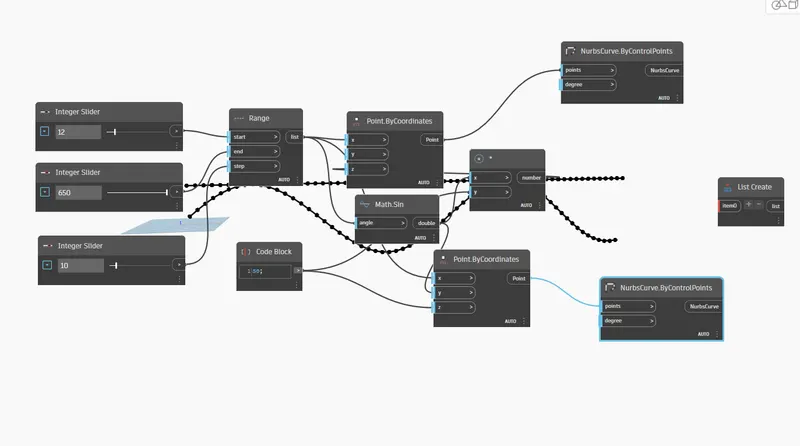
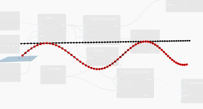
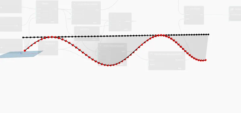
16. Now we create items in the list and create a NURBS curve to connect Item o and a second NURBS curve to connect to Item 1. Now we need to make the surface, type surface by loft option and connect the list to the cross-section. So we will get to the surface.
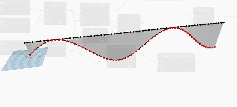
RESULT:
QUESTION NUMBER 2:
Create a conceptual layout of the floor plan in dynamo. Using the tools available in dynamo link the lines to appropriate model elements in Revit by choosing the wall types and wall parameters. Make use of the sliders to slide through the height of the wall and the length of the wall.
AIM:
To create a conceptual layout of the floor plan in dynamo. Using the tools available in dynamo link the lines to appropriate model elements in Revit by choosing the wall types and wall parameters. Make use of the sliders to slide through the height of the wall and the length of the wall.
INTRODUCTION:
Dynamo is a graphical programming interface that lets you customize your building information workflow. Dynamo is an open-source visual programming platform for designers. It is installed as part of Revit along with Revit-specific programming nodes. Dynamo is most often used to analyze BIM data, automate repetitive documentation tasks, and exchange data. In dynamo, we create a conceptual layout of the floor plan in dynamo. Using the tools available in dynamo link the lines to appropriate model elements in Revit by choosing the wall types and wall parameters. Make use of the sliders to slide through the height of the wall and the length of the wall.
PROCEDURE:
1. Open Revit 2023 software.
2. Now Open the Architectural template and go to the manage tab and click it dynamo to open it.
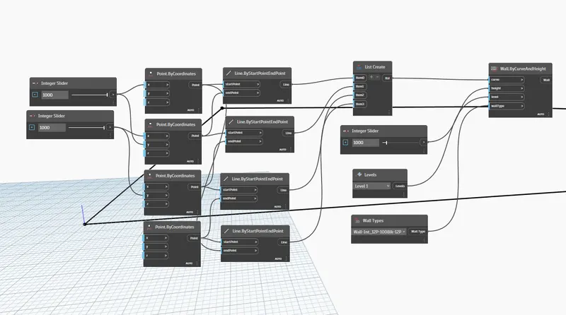
3. To make a wall we need to choose two Integer sliders and type the integer slider in the search bar and inserted it and assign the values 1000 and 1000 respectively.
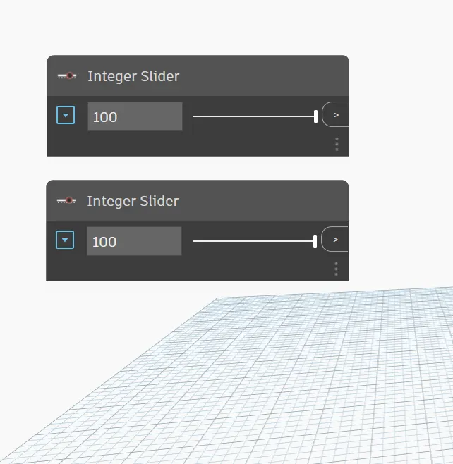
4. After that to draw a wall we need to insert three point-by coordinates inserted into the model space. Then connect the Ist integer slide 1st the point by coordinates on X and to Second Y, then the Second integer slider to the Second point by coordinates on X and the Second integer slider to the third Y. Now complete the points.
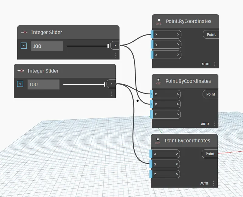
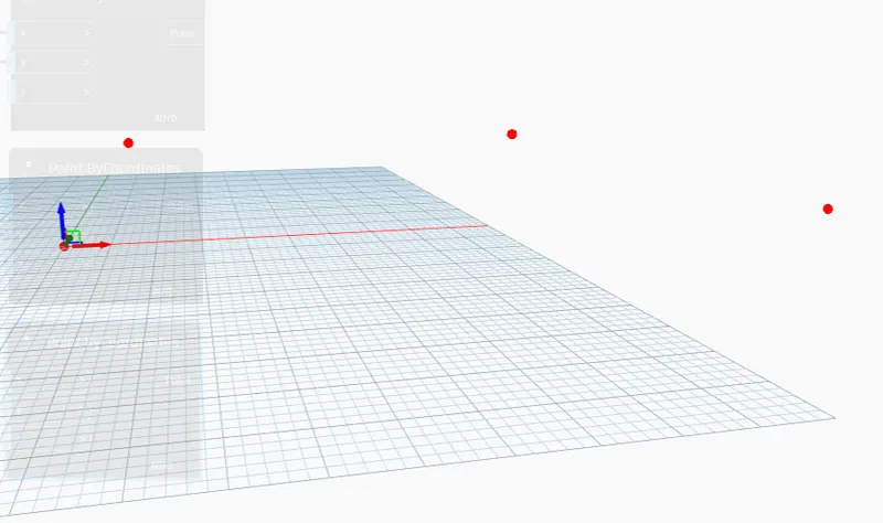
5. Now we need to make the line through these points, Type the line by start and end point to create the 4 Lines by start points. We need to connect the points, the First point as the First start, the Second point as the First endpoint, the First point to the Fourth endpoint, the Second point to the second start point, the Third point to the Second endpoint, the Third point to third start, Fourth point to third end and Fourth point to Fouth start. Now complete the wall creation.
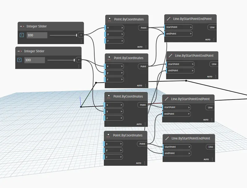
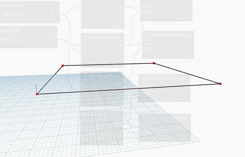
6. Now we need to make a complete wall, The lines are connected to the list option, Go to the search bar and type the list option and add four items simultaneously. Now connect the lines into a list of items.Now we created the wall.
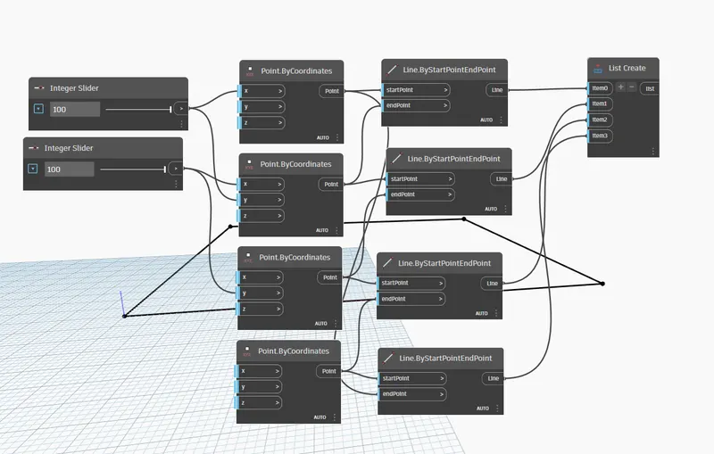
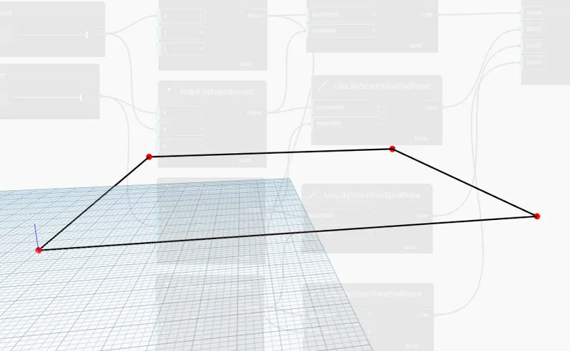
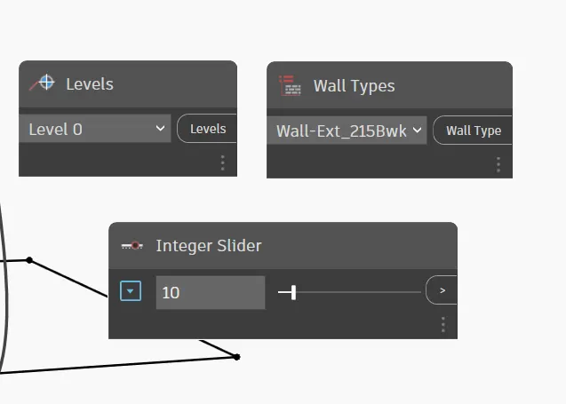
7. After that, we need to set up levels, wall types, and floors, Go to search bar type level, wall type, and inserted in one integer slider. Now select the levels as level 0 and wall type is selected as anyone and the integer value as 10.
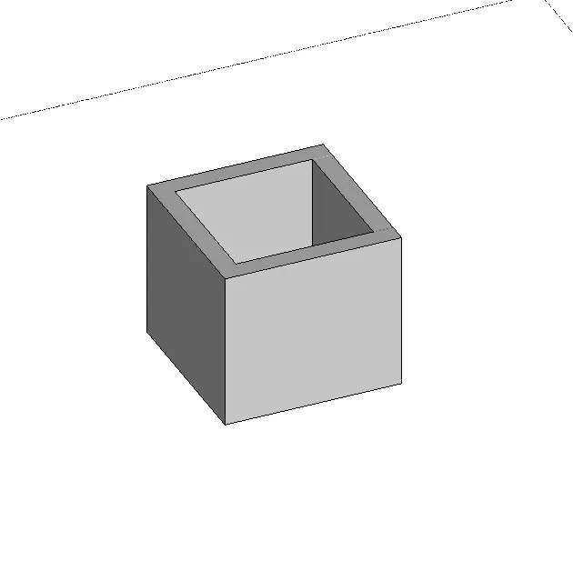
8. Now we need to connect with the wall by curve and height option. Now List to curve, Level to level, Wall type to wall type, and integer slider to height.
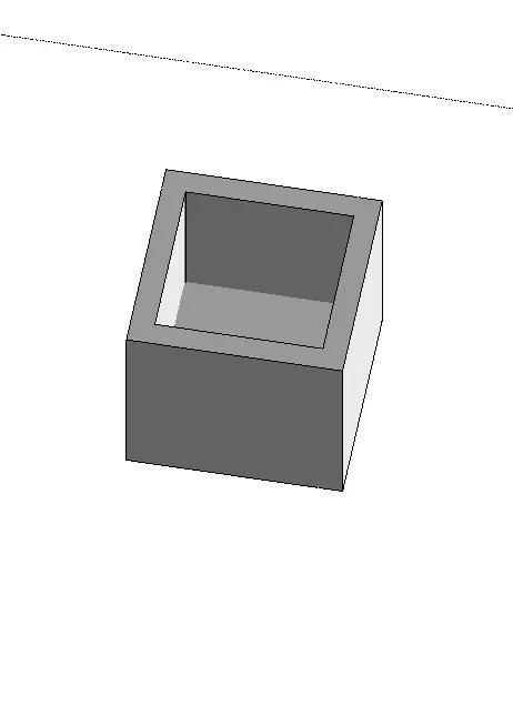
9. Now create the Floor, Go to the search bar and type floor types and floor outline type to insert it. Now List to connect the outline curves and now select floor type to connect to floor type and level as level.
RESULT:
QUESTION NUMBER 3:
Create an array of model elements in Revit. Use dynamo to vary the properties of model elements by using the slider or code block
AIM:
To Create an array of model elements in Revit. Use dynamo to vary the properties of model elements by using the slider or code block
INTRODUCTION:
Dynamo is a graphical programming interface that lets you customize your building information workflow. Dynamo is an open-source visual programming platform for designers. It is installed as part of Revit along with Revit-specific programming nodes. Dynamo is most often used to analyze BIM data, automate repetitive documentation tasks, and exchange data. In dynamo, we create a conceptual layout of the floor plan in dynamo. Easy to Create an array of model elements in Revit. Use dynamo to vary the properties of model elements by using the slider or code block.
PROCEDURE:
1. Open Revit 2023 software.
2. Now we have to provide one column in Architectural Template and placed 4 columns in the required positions.
3. Now Open the Dynamo and go to the manage tab and click it dynamo to open it.
4. Now choose the model elements option, Go to the search bar and type model elements, and select the multiple model elements.
5. Now I need to rotate the column at 45 degrees. Then we go to the search bar and type rotation with family instance and to assign angle then we need to integer slider again go to the search bar type integer slider inserted in model space respectively. These are the basic tools for creating the array.
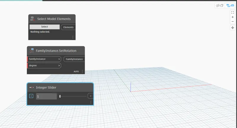
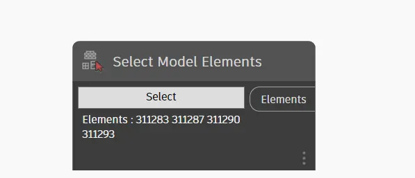
6. After that, we have to select model elements in Revit for that we have to select an option then open Revit, and select all components then it will be selected.
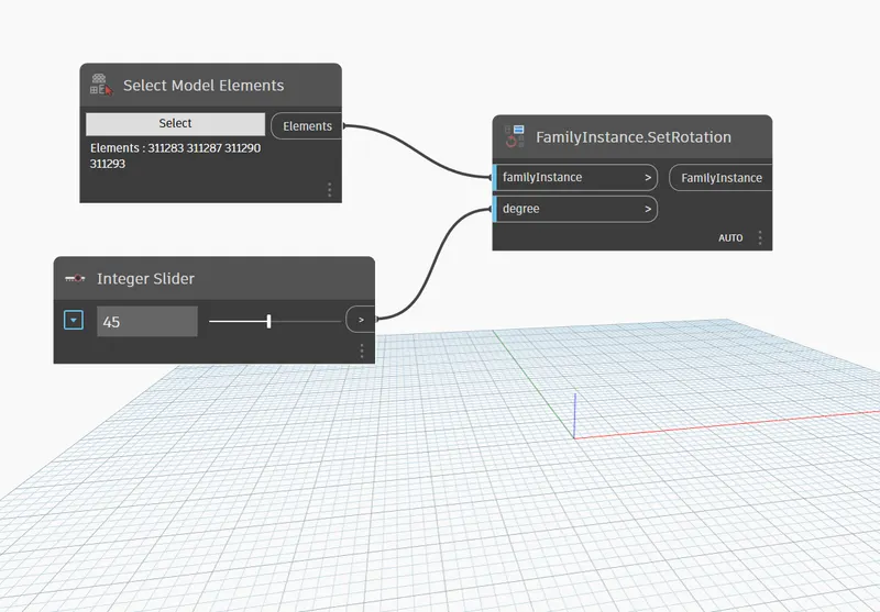
7. Now choose the Rotation angle of 45 degrees, then the elements connected into the family instances and integer slider connected into the degree. Now check in Revit columns are rotated for 45 degrees.
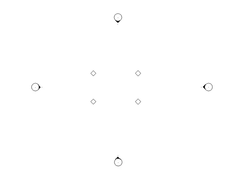
RESULTS:
QUESTION NUMBER 4:
Create a conceptual mass in Revit and develop a parametric column by dividing the surfaces and applying concepts similar to those used in parametric walkway modeling. Use triangular bent or square-shaped panels to add a finish to the parametric column
AIM:
To Create a conceptual mass in Revit and develop a parametric column by dividing the surfaces and applying concepts similar to those used in parametric walkway modeling. Use triangular bent or square-shaped panels to add a finish to the parametric column
INTRODUCTION:
created an in-place conceptual mass element in Revit and would like to know if it is possible to visualize it with a material applied to it. During the conceptual design phase, create masses to explore ideas and perform early analyses. As the design matures, manipulate these forms to use as the basis for more detailed architecture. It is very important to create the conceptual mass in Revit and develop a parametric column by dividing the surfaces and applying concepts similar to those used in parametric walkway modeling.
PROCEDURE:
1. Open Revit 2023 software.
2. Now we need to create Conceptual mass, Go to the File to select a new option and select conceptual mass and click the metric mass and click open.
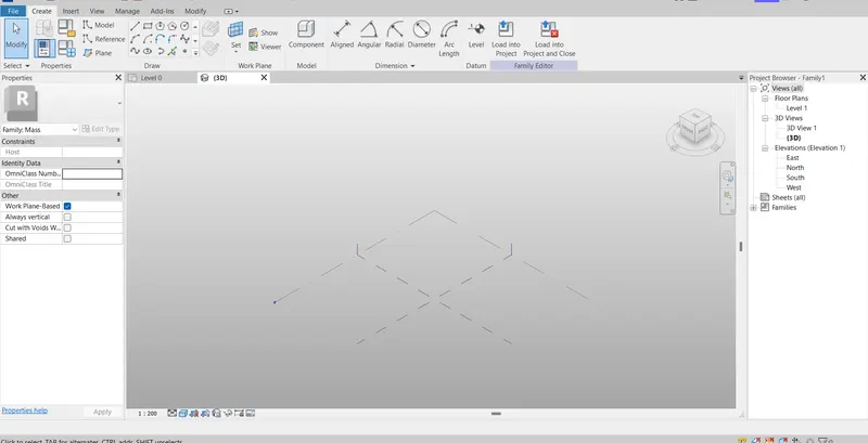
3. Now set the elevation levels, Go to elevation and select levels up to 12'.Now go to floor plan and click create an option to select the model line and choose the spline option and inserted it in the model space in appropriate positions.
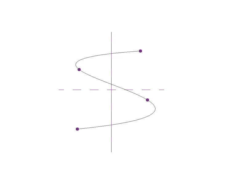
4. After that Go to 3D view and set the plane, Go to the set option for required spline positions. Now we have to select a circumferential polyline at a height of 12'.
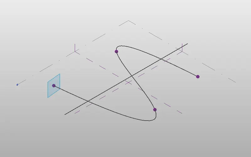
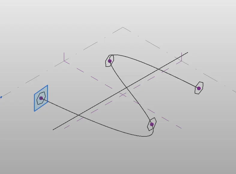
5. Now we need to make this plane as a form option, Go to the crate to click the curve and select the polygon and drop down the create form, and select the solid option. So we get the Solid option.
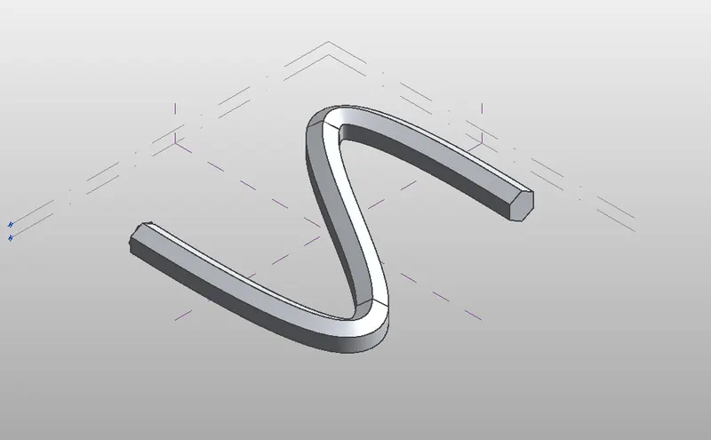
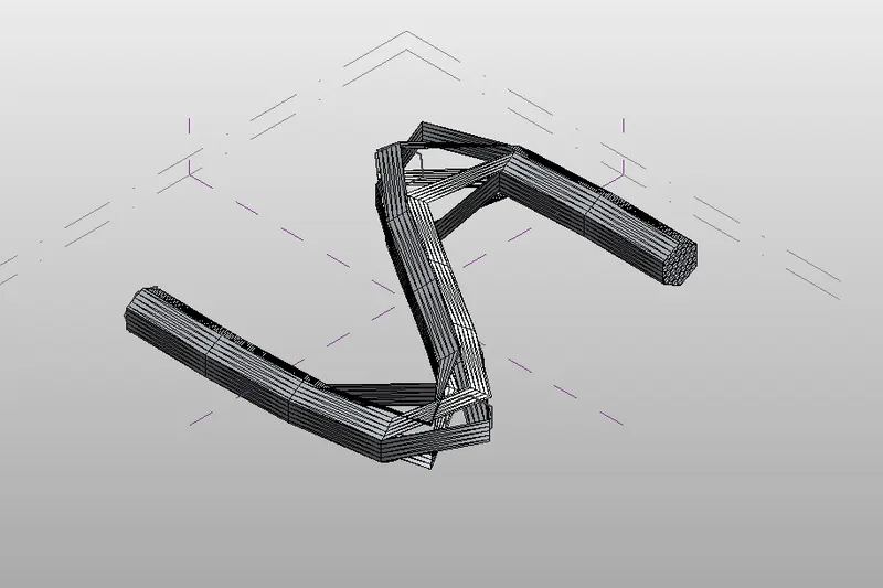
6. In order to make the triangular bent option, Now click all the solids and filter its only form, and click ok. Now select the solid surface and select the divide surface option and then select triangular bent in the properties browser.
RESULTS:
QUESTION NUMBER 5:
Use Dynamo to work on developing a Parametric Stadium. List your parameters and use the visual programming approach to complete the modeling, You can use the concepts discussed in the parametric high-rise tower in class for reference.
AIM:
To Use Dynamo to work on developing a Parametric Stadium. List your parameters and use the visual programming approach to complete the modeling, You can use the concepts discussed in the parametric high-rise tower in class for reference.
INTRODUCTION:
Dynamo is a graphical programming interface that lets you customize your building information workflow. Dynamo is an open-source visual programming platform for designers. It is installed as part of Revit along with Revit-specific programming nodes. Dynamo is most often used to analyze BIM data, automate repetitive documentation tasks, and exchange data. In dynamo, we create a conceptual layout of the floor plan in dynamo.
PROCEDURE:
1. Open Revit 2023 software.
2. Now Open the Architectural template and go to the manage tab and click it dynamo to open it.
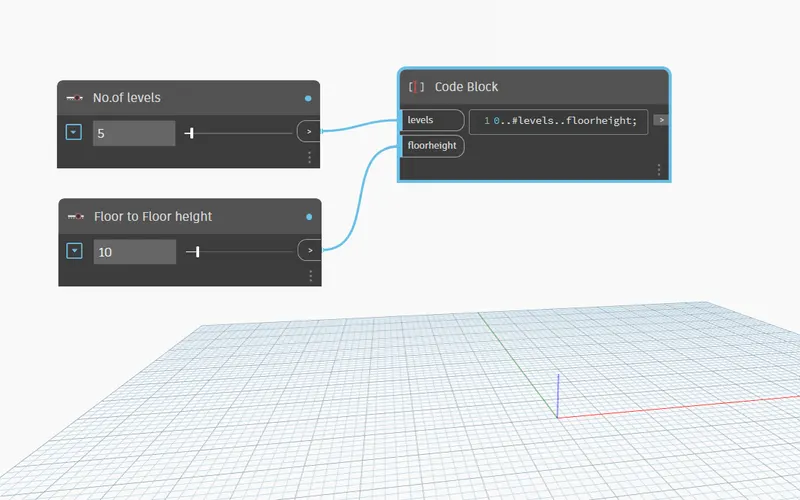
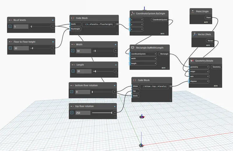
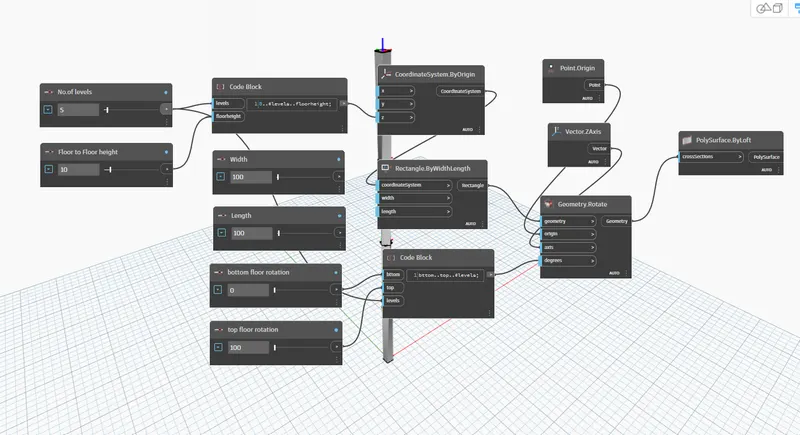
3. Now we need to create integer sliders, Go to the search bar and type the integer slider inserted into the model space. We need Two types of Integer sliders named the number of levels and floor-to-floor height. The final set levels as 5 and the Height is 10.
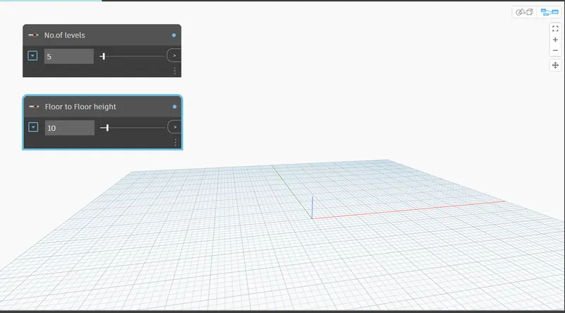
4. After that, create the code block, in the code block provides the 0..#levels..Floor height.Now connect the levels to levels and Floor height to floor height.
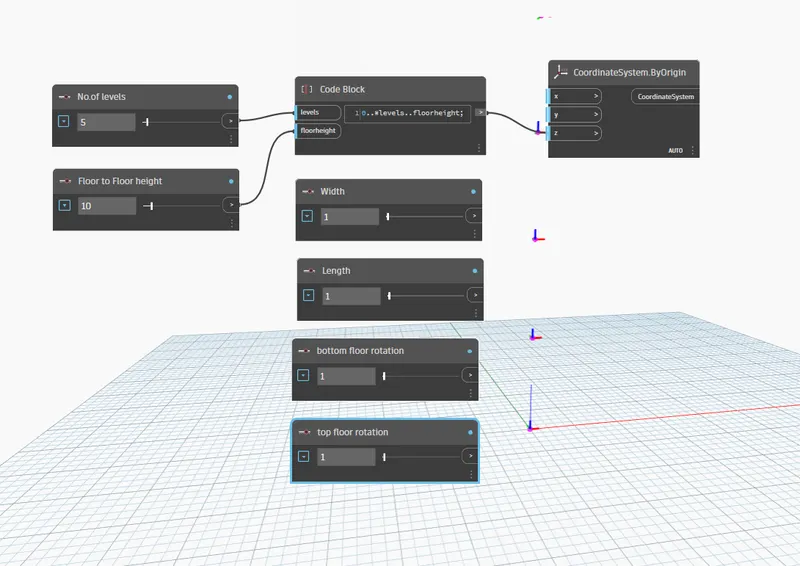
5. Now we need to describe the length and width of the building, then we need point by coordinates, To create and go to the search bar and type the coordination system by origin inserted into model space and connect the code block to the Z and to insert the integer sliders for 4 and name it as a width, length, bottom floor rotation, and top floor rotation.
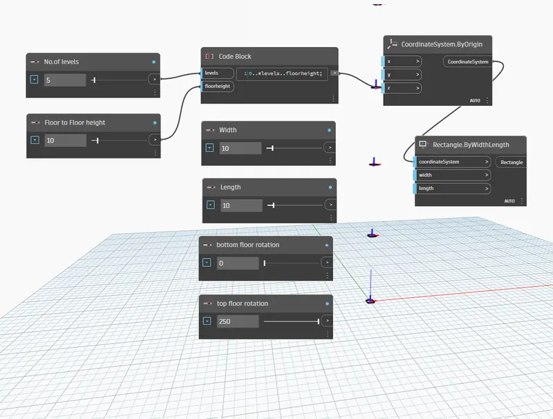
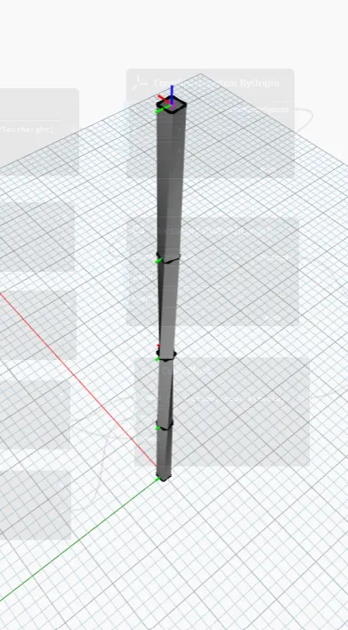
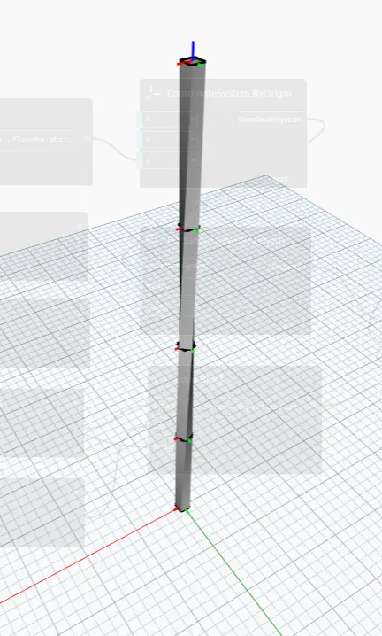
6. After that, we have to insert the rectangular option for that go to the search bar and type rectangle by width and length to insert it. Finally connected to the coordination system to a rectangle and the values are given to the Width as 10, length as 10, bottom floor rotation as 0, and top floor rotation as 250.
7. Now we need for code block for floor rotations and name it as a bottom..top..#levels; Now connect the bottom to bottom, top to top, and Number of levels to levels to levels.
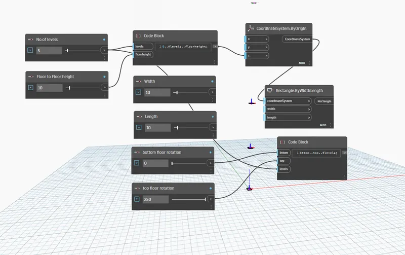
8. After that create an origin point, Vector. Z axis, and rotate geometry. Now we need to connect the rectangle to the geometry, point to the origin, vector Z axis to axis, and code block into degrees.
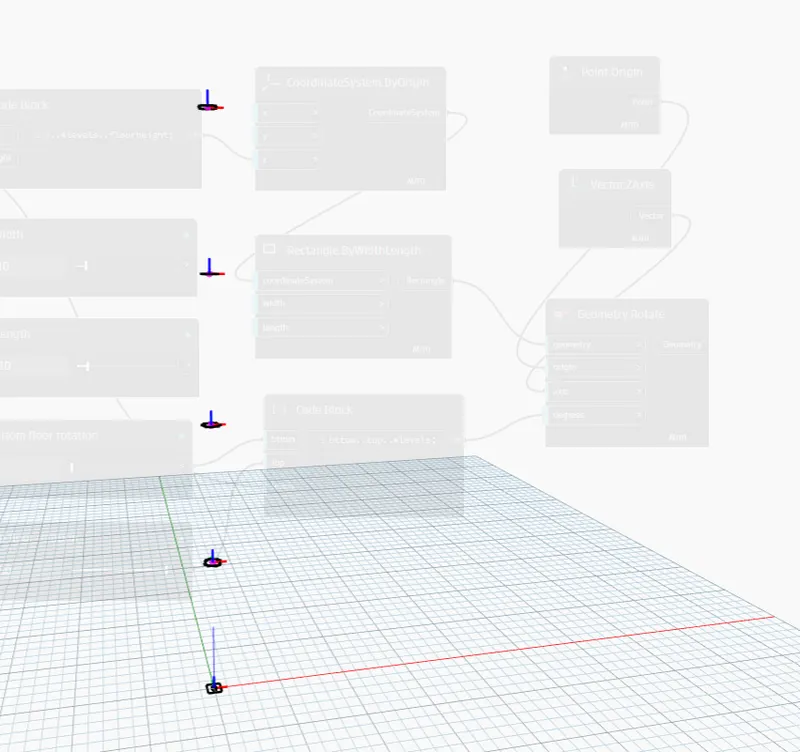
7. Now we need to make the surface of the parametric stadium, Go to the search bar and type poly surface by loft inserted it. Now connected to the geometry to cross sections, So we have to create a parametric structure using code blocks in the dynamo.
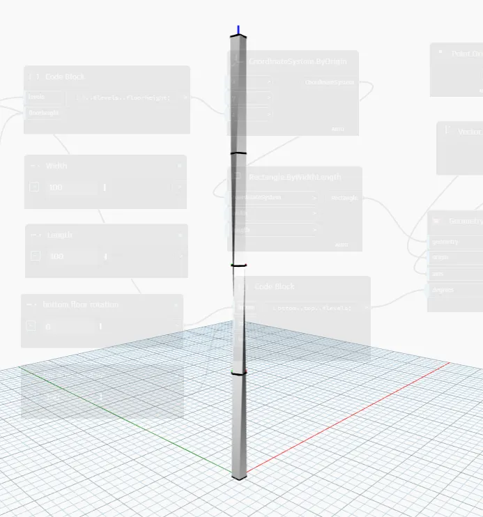
RESULTS:
............................................................................END..........................................................................................